Flexible Body Modify (NLFE)
This dialog box can also be accessed in the following ways:
■Right-click non-linear flexible body → Modify (shortcut: Double-click)
■Right-click non-linear flexible body in Model Browser → Modify
■From the standard menu bar: Select the non-linear flexible body and click on Edit Menu → Modify
Let's you modify a non-modal flexible body that was created using a Nastran .bdf file as input. For example, you can activate or deactivate load cases read from the input BDF file during the simulation, by making modifications in this dialog box.
For the option: | Do the following: |
|---|---|
Flexible Body | Enter the name of the flexible body to modify. |
Datum Node | Set the datum node on the flexible body for which you want deformation color changes to be relative to during animation otherwise Adams View considers the deformation to be relative to the origin of the flexible body (its local body reference frame, LBRF) which, for nonlinear flexible bodies, is the origin of the model and will not move with the flexible body during the simulation. For example, if you were modelling a beam that is clamped at one end to a moving part, you could specify that deformations should be relative to a node on the clamped end. Otherwise, the deformation color would include the total displacement of the flex body which may not be as important to visualize in color. To set the datum node: 1. Clear the selection of LBRF. 2. In the Datum Node text box, enter the number of the desired node. Note: To select a node from the screen, right-click the Datum Node text box, and then select Pick Flexbody Node. Select the node from the screen. The node number appears in the Datum Node text box. |
Location | Click to display the Modify Body - Name and Position dialog box and set the name, Adams Solver ID, and location of the flexible body. |
Number of Threads | Specifies the number of threads to be used on each nonlinear flexible body. A separate process is used to solve a nonlinear flexible body. To specify more than one thread in solving a flexible body on this process, set Number of threads > 1. Typical, values are 1 through 4. |
Position ICs | Click to display the Modify Body - Position Initial Conditions dialog box and set the initial position for a flexible body before the simulation starts, just as you can for any part in Adams View. You can set how you want Adams View to calculate these properties as well as define these properties yourself. |
Velocity ICs | Click to display the Modify Body - Velocity Initial Conditions dialog box and set the initial velocity for a flexible body before the simulation starts just as you can for any part in Adams View. You can set how you want Adams View to calculate these properties as well as define these properties yourself. |
Compute Resource | Specifies the name of a remote host machine for solving the nonlinear flexible body. If specified and before launching a simulation, the NLFE name server has to be started on the remote host machine, and then the remote kernel has to be started on the machine where Adams is running using the Adams-NLFE Client Manager. For more information on the Adams-NLFE Client Manager see “Using Distributed Computing for Nonlinear Adams Flex Bodies” in Chapter 7 of the Installation and Operations Guide. |
Damping Tab - If the input BDF contains DAMPING information, this is used to populate the following fields. If these cards are not present in the BDF, the default values are displayed for the fields. See the MSC Nastran Quick reference Guide for more information on these fields belonging to the DAMPING card. | |
Structural Coefficient (G) | Specifies the structural damping coefficient. Enter a real number (default is 0). |
Rayleigh Mass Factor (ALPHA1) | Specifies the scale factor for mass portion of Rayleigh damping. Enter a real number (default is 0). Rayleigh viscous damping is calculated as:  |
Rayleigh Stiffness Factor (ALPHA2) | Specifies the scale factor for stiffness portion of Rayleigh damping. Enter a real number (default is 0). Rayleigh viscous damping is calculated as: 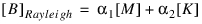 |
Material Factor (GEFACT) | Specifies the scale factor for material damping. Enter a real number (default is 1). Structural damping specified by the G and GEFACT entries will replace any structural damping by: new[K4] = G[K] + GEFACT[K4]. The GFACT value used is GEFACT = GE (default=0.0) * GEFACT (default=1.0) where GE is the structural damping value on the material entry. |
Structural Frequency (W3) | Specifies the average frequency for calculation of structural damping in a transient response. Enter a real number >= 0 (default is 0). The W3 and W4 values are used in transient response only. A zero value (default) will result in no damping. The equivalent viscous damping is calculated as:  |
Material Frequency (W4) | Specifies the average frequency for calculation of material damping in a transient response. Enter a real number >= 0 (default is 0). The W3 and W4 values are used in transient response only. A zero value (default) will result in no damping. The equivalent viscous damping is calculated as: 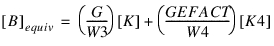 |
Load Cases Tab - Building Flex Body Models > Load Case Selection. | |
Graphics Tab | |
Substituting Graphics with an Outline (Learn more about Substituting Outline Graphics for the Finite Element Mesh.) | |
Full graphics | Select to turn on the viewing of the full graphics; clear to turn off the viewing. |
Outline | Select to turn on the viewing of the Outline. |
 | Select to sketch an outline. To sketch the outline: ■Select nodes on the flexible body using the left mouse button. ■When the outline is complete, right-click. |
Contour Plots | Sets Adams View so that it displays Contour plots. In addition, you can view contour plots in Adams PostProcessor. Note: When animating deformation while the analysis is still running, the color scale can only take into account the maximum deformation to that point in the simulation; so, the colors may appear differently when animating partial results as opposed to when animating a completed analysis. |
Deformation Scale | Change the Deformation Scale Factor text box value to change the amount by which a flexible body will displace. For increasing the deformation scaling, type a value greater than 0 in the text box. Changing the deformation scale lets you exaggerate deformations that might otherwise be too subtle to see, or lets you limit the deformations. The default scale factor is 1. Note: Setting the scale factor to a value other than 1 can make the joints at the flexible body appear to separate. This is because the total displacement of each point on the flexible body will be magnified. In addition, if you set the scale to 0, the flexible body will not move during animations. |
 | Select to add any comments to help you manage and identify the flexible body. See Comments. |
Results Tab | |
Stress | This option controls the stress output to the Nastran result file (.op2 file) during the simulation. If this option is not set, no stress will be computed during the simulation for this flexible body, and you will not be able to post-process them. |
Strain | This option controls the strain output to the Nastran result file (.op2 file) during the simulation. If this option is not set, no strains will be computed during the simulation for this flexible body, and you will not be able to post-process them. |
FEA Settings Tab | |
Self Contact | Select to enable self-contact for this flex body during the simulation. Default is off. Contact could increase the solution time so only use this option if you think the flexible body may come in contact with itself. Furthermore, the originating BDF must be setup for self-contact in the finite element pre-processor. Specifically, there must be a "BCBODY" statement in the bulk data section referencing a "BSURF" that defines the specific elements to be used for contact detection. If the case control section of the original BDF also has a "BCONTACT" statement then its ID is applied to the run-ready deck (.dat) which Adams View creates. If not, the youngest ID of the "BCBODY" statements in the BDF is applied. If the self-contact option is checked and no "BCBODY" is present then the self-contact is deactivated. A "BCTABLEx" statement might also be present in the originating BDF for defining the details of the contact bodies (which ones contact which others). If no "BCTABLEx" is found then all BCBODYs can contact each other and then the CPU time for the analysis may be significantly larger than if anticipated contact is specified in a "BCTABLEx." |
Automatically Allocate Memory | If selected, the nonlinear flex body process will take half of the physical memory on the machine that it is executed on. If more than one nonlinear flexible body is being solved on the same machine, this setting is divided by the number of flex bodies. One should be careful to leave some memory for the Adams process to run if it is executing on the same machine. |
Memory Scale Factor | If selecting "Automatically Allocate Memory" this field can optionally be used to manually specify the fraction of the machine's memory to be used to solve this nonlinear flexible body. Enter a real number between 0 and 0.8. Be careful to leave some memory for the Adams process or other processes if they are executing on the same machine. By default, here, Adams uses a value of 0.5 divided by the number of nonlinear flexible bodies in the model solved on the same machine. One may want to use this setting if they do not want to evenly distribute memory to each flexible body in the model because some are much larger than others. If, for example, the model has three nonlinear flexible bodies where two are relatively small compared to another, then one may want to set Memory Scale Factor to 0.4 for the large one and 0.05 for the two smaller ones. |
Memory Setting | If "Automatically Allocate Memory" is not selected, then specify the precise amount of open core memory (in MB) to allocate to this nonlinear flexible body. Be careful to leave some memory for the Adams process or other processes if they are executing on the same machine. |
Buffer Size | Select from one of the following: ■ "Auto" ■"8193 Words" ■"16385 Words" ■"32769 Words" ■"65537 Words" This specifies the number of words in a physical record. If "Auto" is selected, then the Buffer Size is computed internally based upon the degrees of freedom of the Non-Linear flexible body. Please refer to the Note below, Estimating BUFFSIZE, for more details. |
Notes: | 1. Units (Mass, Length, Force and Time) specified in this dialog box indicate the Nastran units specified in the BDF or while creating the non-linear flexible body and cannot be modified using the Flexible Body Modify dialog box. If you wish to use different units from what was specified during creation, please delete the flexible body and recreate it again with the desired units. |
2. Estimating BUFFSIZE: The Table 4‑1 presents recommendations for BUFFER SIZE based on model size. These values have been chosen to represent the best compromise between database access speed and storage requirements for typical problems. An excessively large BUFFER SIZE can result in more I/O data transferred and wasted space in the database for smaller problems; an excessively small BUFFER SIZE can result in increase I/O counts for larger problems. You may be able to achieve higher performance or smaller database using other values. The Default Buffer Size is set to "Auto", in which the Degrees of Freedom (DOF) will be computed approximately using the Nastran Estimate functionality and the Buffer Size is then selected based on the Table 4‑1 below. The DOF can also be computed approximately by the following formula: DOF ~= (Number of nodes on solid elements)* 3 + (Number of nodes on the other elements) * 6 The Buffer Size can be then selected based on Table 4‑1. |
Table 4‑1 Suggested BUFFER SIZE Values
Degrees of Freedom(DOF) | BUFFER SIZE(words) |
|---|---|
DOF ≤ 100000 | 8193 |
100000 < DOF ≤ 400000 | 16385 |
400000 < DOF ≤ 1,000,000 | 32769 |
DOF > 1,000,000 | 65537 |