Visually Investigating Results
Because Adams Flex is built right into Adams View, you can view the deformations of each mode and change their visual display to help you investigate the results of the simulations. The next sections explain how you can change the visual display to investigate the deformations of your flexible body.
Substituting Outline Graphics for the Finite Element Mesh
When you build a flexible body into Adams View, Adams Flex creates a mesh on the body based on the description of the flexible body in the Modal Neutral File (MNF). Often flexible bodies are based on a finite element model with such a high level of detail that it stretches the capabilities of your graphical hardware. In other cases, the detailed mesh can hide other modeling elements.
If you encounter either of these, you can substitute a graphical outline for the graphics from the MNF by sketching an outline.
Note: | To reduce animation times, you can also set Adams Flex so it treats the flexible body as a rigid body during animations. For more information, see Scaling the Deformations. In addition, you can use the MNF optimization capabilities of the Adams Flex toolkit to permanently reduce the complexity of MNF geometry. For more information, see Optimizing an MNF or an MD DB. |
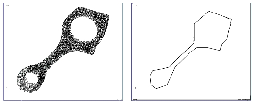
Outline Graphics Applied to a Flexible Body
To sketch an outline:
1. Access the Flexible Body Modify dialog box as explained in the Accessing the Flexible Body Modify Dialog Box.
2. Select the Graphics Outline tool  .
.
. 3. Draw the outline by selecting nodes on the flexible body using the left mouse button.
4. When the outline is complete, select the right mouse button.
To turn on the viewing of the outline:
■In the Flexible Body Modify dialog box, under the Graphics section, select outline.
To turn off the viewing of the full MNF graphics:
■In the Flexible Body Modify dialog box, under the Graphics section, clear the selection of full MNF graphics.
To delete an outline:
1. Right-click the outline graphic you want to delete.
2. From the shortcut menu that appears, select Delete.
3. In the Flexible Body Modify dialog box, under the Graphics section, clear the selection of outline.
Scaling the Deformations
You can change the amount by which Adams Flex deforms a mode. You can exaggerate deformations so you can see deformations that might otherwise be too subtle to see, or you can limit the deformations. The default scale factor is 1.
Note that setting the scale factor to a value other than 1 can make the joints at the flexible body appear to separate. This is because the motion of a point on a flexible body is the sum of the deformation that has been scaled and a rigid body motion that is not scaled.
In addition, if you set the scale to 0, Adams Flex treats the flexible body as a rigid body during animations.
To scale the deformations:
1. Display the Flexible Body Modify dialog box as explained in Accessing the Flexible Body Modify Dialog Box, if necessary.
2. Move the Deformation Scale Factor slider to the desired scale value or, for greater exaggeration, type a value in the text box next to the slider.
3. Animate the flexible body to see the changes. Learn Playing an Animation.
Adams Flex now exaggerates the deformations of the flexible body by the amount you requested.
Adding Contour or Vector Plotting
You can set Adams Flex so that it displays Contour plots or Vector plots.
In addition, in Adams PostProcessor, you can view the contours of deformations, as well as modal forces and stress and strain results you obtained using Adams Durability. For more information on displaying contour and vector plots in Adams PostProcessor, see Animating Flexible Bodies and Adams Durability Results.
By default, Adams Flex considers the deformation to be relative to the origin of the flexible body (its local body reference frame (LBRF) or coordinate system). You'll notice that at the start of the animation, the flexible link is completely blue. As the animation runs, it changes to red to indicate where and when the maximum deformation occurred.
To set color contouring or vector plots:
1. Display the Flexible Body Modify dialog box as explained in the Accessing the Flexible Body Modify Dialog Box, if necessary.
2. Set Plot Type to Contour or Vector. You can also set it to Both.
3. Animate the flexible body to see the changes. Be sure to turn on the display of contour plots by selecting Contour Plots in the Animation Controls dialog box in Adams View. See Using Animations.
Notice that there is a short hesitation before the animation starts because Adams View computes and scales colors based on the deformation that occurred during the simulation.
Specifying a Deformation Datum Node
You can set the datum node for which you want deformation color changes to be relative to using Adams Flex. Adams Flex considers the deformation to be relative to the origin of the flexible body (its local body reference frame (LBRF) or coordinate system) by default. For example, if you were modeling a cantilever beam in Adams Flex, you could specify that deformations should be relative to the clamped end as was illustrated in the first tutorial, Building and Simulating a Flexible Model, of Getting Started Using Adams Flex.
To specify a datum node:
1. Display the Flexible Body Modify dialog box as explained in Accessing the Flexible Body Modify Dialog Box, if necessary.
2. Clear the selection of LBRF.
3. In the Datum Node text box, enter the number of the desired node.
Tip: | To select a node from the screen, right-click the Datum Node text box, and then select Pick Flexbody Node. Select the node from the screen. The node number appears in the Datum Node text box. |
4. Select OK.
Filtering Modes
You can select a filter type to remove modes from the animation display. By default, all enabled modes are used to generate nodal displacements for each flexible body during animations. To increase animation performance, Adams Flex has three filters that let you remove graphically insignificant modes for animations. A mode that is filtered out is excluded from the modal superposition and any contribution to the deformation of the body is ignored. Note that these modes are not filtered out for numeric operations, such as signal processing or xy plotting.
To create a filter:
1. Display the Flexible Body Modify dialog box as explained in Accessing the Flexible Body Modify Dialog Box, if necessary.
2. Select Mode Filter.
The Flexible Body Mode Filter dialog box appears.
3. In the Flex Body text box, enter the name of the flexible body.
4. Set Filter Modes By to the desired mode:
■None - Includes all modes for computing the graphics display.
■Frequency - Excludes any mode that is activated above the specified frequency.
■Min Displacement - Excludes any mode that does not contribute the minimum displacement specified for at least one vertex of the flexible body. For example, if you are viewing the animation of a vehicle driving down the road, it is unlikely that you would be able to see deformations of 0.5 mm or less. Therefore, if you set a mode filter value of 0.5, any mode that contributes less then 0.5 is considered insignificant and is ignored for animations. This calculation is performed at each frame of the animation, allowing the set of significant modes to change throughout the simulation.
■Percentage - Determines the maximum displacement contributed by all modes, and excludes any mode that doesn't contribute displacement of one vertex at least as significant as a percentage of the maximum. For example, setting the percentage filter at 15% excludes any mode not contributing at least 15% of the most dominant mode. This calculation is performed for each frame of the animation, therefore, allowing the set of significant modes to change throughout the simulation.
5. In the Filter Value text box, enter the frequency, minimum displacement, or percentage for the specified filter.
6. Select OK.
7. Animate the flexible body to see the changes.
Animating After a Flexible Body Swap
Caution should be taken when animating prior analyses after substituting a body with a flexible body via either the Rigid-to-Flex swap or the Flex-to-Flex Swap capability. See Replacing Existing Bodies with Flexible Bodies for details on preforming such substitutions.
If one or more analyses which reference the original representation of the substituted body exists in the session, the body will not appear correctly in subsequent animations of those analyses. This is because only the latest representation of that body is stored in the session. So, the visual deformation and any contour plot coloring will no longer be accurate.
The animated motion and color contours of the rest of the model’s bodies will continue to be accurate. Also, any XY-plotting of result sets, requests, or measures will continue to be accurate.