Manage Geometry Options
Geometry Translation Options
The following table shows the options used while importing/exporting geometry data in/from Adams.
The options are applicable for the following formats:
Notes: | ■All but STEP and IGES require the 'Adams Geometry Translators' license. ■The geometry options listed below are not applicable for import of Catia V6 3dxml files in Review mode. This is because Catia V6 files in Review mode generate an STL file during the import process. This is unlike other CAD formats, whose import generates a Parasolid file. |
Import: IGES, STEP, ACIS, CATIA V4, CATIA V5, CATIA V6, Pro/E (and Creo), Inventor, Solidworks, Unigraphics, JT
Export: IGES, STEP
Sew | If set to true, all the bodies are sewed together. The default is 'false'. |
Heal | If set to true, geometry errors are corrected by adjusting data to Parasolid's default precision. The default is 'true'. |
TranslateBodies | If set to true, solid/sheet bodies will be imported. The default is 'true'. |
TranslateWires | If set to true, free curves (curves that are not attached to any surface) will be imported. The default is 'false'. |
TranslatePoints | If set to true, free points (points that are not attached to any curve) will be imported. The default is 'false'. |
TranslateCoordinateSystem | If set to true, coordinate will be imported. The default is ‘false’. |
CATIAV5GeometricSet (applicable for CATIA V5 only) | If set to true, the exact model tree structure is provided for 'Geometric Set' entities as in CATIA V5. The default is 'true'. |
Color (applicable for Unigraphics, Solidworks and JT only) | If set to true, color of the data will be taken into account during import. The default is 'true'. Setting to 'false' may improve import speed under some conditions. |
Use Direct Approach | If set to true, the data translator component will save the data directly into Parasolid. The default is 'false'. Note: Direct approach has some limitations. It is recommended to use this option only if the geometry is not obtained with the default approach. |
Geometry Rendering Options
All geometry imported into Adams View is translated into a Parasolid representation first then used this Parasolid representation to render the geometry. For description of the translation options see Geometry Translation Options. The following table shows the options used while rendering Parasolid geometry data imported into Adams. It also applies for geometry created natively within Adams. This excludes native standard geometry like cylinder, sphere and so on, where direct values like "side count" and so on, control the rendering, but when one applies features (for example, chamfer, hole, fillet and so on.) or boolean operations (union, subtract and so on.) these geometry rending options will also apply. When you set these geometry rendering options, these option will be applicable for all consecutive import operations until you change it, in that session. Existing geometry in the model will also be affected by the new rendering options. You can use different options for individual pieces of geometry by changing the options for each import operation. When you save the model as .bin, these options will persist the last set values and these saved options will be used for all the geometry objects in that model. Other than .bin, these options will not persist in any way outside of the session (for example, when exporting a .cmd file). If you used different settings upon import of different pieces of geometry in a session, there is no way to apply these same geometry-specific settings to a future Adams session. Instead, you must determine a single set of values which renders ALL pieces of geometry in your model to your liking and then apply those values to future sessions either manually or through an aviewBS.cmd or acarBS.cmd.
You can also set geometry rendering options through the Adams View command language (see defaults geometry command for more details).
CurveChordToleranceScale | Curve chord tolerance scale is the multiplying factor for the curve chord tolerance. Curve chord tolerance is the maximum chordal distance between a facet edge and its original edge entity. The default value is 0.3 If the curve chord tolerance scale is less than 0.3, the tessellation will be finer. A value greater than 0.3 will result in a coarser tessellation. 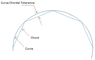 |
CurveChordAngle | Curve chord angle is the maximum angle (always in radians, irrespective of model units) which is permitted between a facet chord and its original edge entity. The default is 0.26 (that is 15 deg) which means a value will be automatically set by Adams if it is not explicitly set by the user. Lesser curve chord angle will result in a finer tessellation. Greater angle will result in a coarser tessellation. 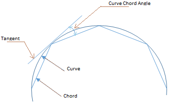 |
SurfacePlaneToleranceScale | Surface plane tolerance scale is the multiplying factor for the surface plane tolerance. Surface plane tolerance is the maximum distance between the mid-plane of a facet and its original face entity. The default value is 0.3. If the surface plane tolerance scale is less than 0.3 the tessellation will be finer. A value greater than 0.3 will result in a coarser tessellation. 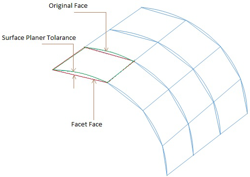 |
SurfacePlaneAngle | Surface plane angle is the maximum angle (always in radians, irrespective of model units) which is permitted between the surface normal at any two positions on the surface which lie within the facet boundary. The default is 0.26 (that is 15 deg) which means a value will be automatically set by Adams if it is not explicitly set by the user. Lesser surface plane angle will result in a finer tessellation. Greater angle will result in a coarser tessellation. 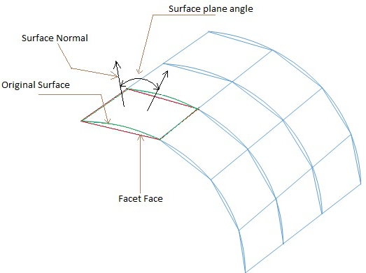 |
Note: | Finer or coarser tessellation will impact performance in loading the model and all graphics operations like view manipulation, wireframe/shaded mode change and so on. Finer tessellation will result in better rendering but will negatively impact the performance. Coarser tessellation will improve the performance but will negatively impact the rendering quality. |