Example of Adding a Sensor
Overview
The following example demonstrates how to use a sensor to stop a simulation. In the example, you import an Adams View command file that builds a model of a garage-door mechanism. In the example, you will add a sensor to the model to stop the simulation when the bottom of the door reaches the ground. The garage door model is composed of several rigid sections hinged together, just as many typical garage doors are.
You construct the sensor so it monitors the vertical component of distance between a point on the bottom tip of the lowest door section and the global xz plane and stops the simulation when this distance becomes approximately equal to zero.
Mathematically, the following relationship defines the sensor:
Halt the simulation if DY between tip and ground ≤ 1.0E-3
If this never occurs, run to normal completion
We’ve provided you with two command files that you can use depending on how much of the example you want to do yourself:
■gdoor_without.cmd - Model with no sensor defined.
■gdoor_with.cmd - Model with sensor defined.
You can also use gdoor_with.cmd if you encounter difficulties with the example or want to check your work. Use the Simulate → Sensor → Modify menu to see how we created SENSOR_1.
The files are in the directory /install_dir/examples/user_guide, where install_dir is the directory in which Adams software is installed.
The example is divided into the following sections:
Importing the Command File
To import the command file to create the garage door:
1. Copy the command file gdoor_without.cmd to your local directory.
Note: | By default on Windows, files in the installation directory are read-only. During installation, your system adminstration can choose to change the permissions so you can write to the installation directory. If this has not been done, you will need to change the permissions of the above file when you copy them to your working directory. |
2. Start Adams View and import gdoor_without.cmd.
You should see the model, shown on the next page, in your modeling window. A strip chart also appears. It tracks the height of the door.
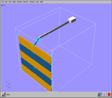
Figure 8 Garage-Door Mechanism
Simulating the Model without a Sensor
First, you’ll run a simulation of this model to see how it acts when it does not have a sensor. As the door moves, the measure tracks its height.
To perform a simulation:
1. Perform a dynamic simulation from 0 to 5 seconds with 200 steps.
Without a sensor, the simulation runs to time = 5 seconds even though the bottom tip of the door goes into the ground (that is, below the global xz plane). This does not sufficiently model what happens in the physical world, so you need to add a sensor to enhance the realism of your simulation.
2. Reset the model to its initial configuration.
Adding a Sensor
You’ll now add a sensor that uses the run-time function DY to monitor when the tip of the garage door crosses ground. DY returns the y component of translational displacement from one object, in this case ground, to another object, the bottom tip of the lowest door section. When the y component is 0 within a tolerance of 1.0E-3, the sensor stops the simulation.
To add a sensor:
1. Click the Design Exploration tab. From the Instrumentation container, click the Sensor tool  .
.
.or
(Classic interface) From the Simulate menu, point to Sensor, and then select New.
2. Set Event Definition to Run-Time Expression.
3. Define the Expression to be:
DY(.gdoor.PART_2.tip, .gdoor.ground.frame, .gdoor.ground.frame)
Note: | The shortened form DY(tip, frame, frame) also works. For help in defining this function, right-click the Expression text box and use the Function Builder. |
4. Select Non-Angular Values to indicate that the expression measures non-angular values.
5. Now set the value to trigger the sensor action:
a. Set the pull-down menu to less than or equal.
b. In the Value text box, enter 0, which is the value to trigger an action.
c. In the Error Tolerance text box, use the default 1.0E-03, which is the allowable error between the targeted value (0) and the actual sensed value.
6. In the Standard Actions section, select Terminate current simulation step.
7. Select Stop.
8. Ensure that all other standard and special actions are not selected.
9. Select OK.
Simulating the Model with a Sensor
Now you’ll simulate the model again to see the effect of adding the sensor.
To perform a simulation:
■Perform a dynamic simulation from 0 to 5 seconds with 200 steps.
The simulation now stops before reaching 5.0 seconds. The last output step should be at time = 4.6 seconds, and you should receive a message similar to the following:
WARNING: Sensor .gdoor.SENSOR_1 halting simulation at time 4.617.
Creating a Sensor with an Event Evaluation
Now you'll create a new sensor that evaluates the y-displacement of the bottom of the door with respect to ground.
To add the sensor:
1. Click the Design Exploration tab. From the Instrumentation container, click the Sensor tool .
.or
(Classic interface) From the Simulate menu, point to Sensor, and then select New.
2. Set Event Definition to Run-Time Expression.
3. Define the Expression to be:
MOD(time, .5)
Note: | This will cause the sensor to evaluate every .5 seconds. |
4. Set Event Evaluation to Run-Time Expression.
5. Define the Expression to be:
DY( PART_2.tip, ground.frame, ground.frame)
Note: | This will measure the y-displacement of the bottom of the door with respect to ground. |
6. Select Non-Angular Values to indicate that the expression measures non-angular values.
7. Set the value to trigger the sensor action:
a. Set the pull-down menu to equal.
b. In the Value text box, enter 0.
c. In the Error Tolerance text box, enter 0.05.
8. In Standard Actions, select Generate additional Output Step at event.
9. Ensure that all other standard and special actions are not selected
10. Select OK.
Now you'll create a function measure to track the evaluation of the sensor.
To create a function measure:
1. Click the Design Exploration tab. From the Measures container, click the Function measure tool  .
.
.or
(Classic interface) From the Build menu, point to Measure, point to Function, then select New.
2. In the function work area, enter:
SENVAL(SENSOR_2)
3. Select OK.
A strip chart appears to track the value of the function measure.
Now you’ll simulate the model.
To simulate the model:
■Perform a dynamic simulation from 0 to 5 seconds with 200 steps.
The strip chart shows the y-position of the door every 0.5 seconds.