Step One - Build the Adams Model
Now you’ll import an Adams model and familiarize yourself with its construction by following the next four sections:
Build the Adams Model
1. Select Import a File.
2. In the Start In text box on the Adams View welcome screen, enter the name of your new directory (the one created in Step 1. in To start Adams View: above).
This sets your new directory as your working directory.
3. Select OK to close the Adams View welcome screen.
The File Selection dialog box appears.
5. Select the file antenna.cmd.
6. Select OK.
The antenna model main_olt appears as shown in Figure 1.
7. To change the display of the antenna from a wire frame into a shaded, three-dimensional image, from the Status Toolbar, select  Wireframe/Shaded toggle for current view.
Wireframe/Shaded toggle for current view.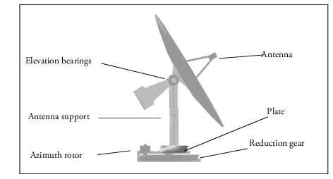
Figure 1 Shaded Model of Antenna
Loading Adams Controls
Because Adams Controls is a plugin for Adams View, you need to load Adams Controls when you use it with Adams View.
To load Adams Controls:
1. From the Tools menu, point to Plugin Manager.
2. Select the Load checkbox next to Adams Controls.
3. Select OK.
Adams View loads the Adams Controls plugin.
Note: | To automatically load Adams Controls each time Adams View starts up, select Load at Startup in the Plugin Manager. |
Familiarizing Yourself with the Model
This model is designed so that its base turns in the azimuthal (horizontal) direction and its antenna tilts in the vertical direction.
To familiarize yourself with the model, locate the following components:
■Azimuth rotor (peach) connected to ground by revolute joint.
■Azimuth reduction gear (sky blue) connected to ground by revolute joint.
■Azimuth plate (magenta) connected to ground by revolute joint.
■Antenna support (silver) connected to plate by fixed joint.
■Elevation bearings (peach) connected to support by fixed joint.
■Antenna (sky blue) connected to bearings by revolute joint.
■rotor_gear, couples the revolute joint at the rotor to the revolute joint at the reduction gear.
■gear_plate, couples the revolute joint at the reduction gear to the revolute joint at the plate.
Running a Trial Simulation
To run a trial simulation with Adams View:
1. Click the Simulation tab on the Adams View ribbon.
2. From the Simulate container, click the Interactive Simulation tool .
.
. 3. Enter the following in the Simulation Controls dialog box:
■End Time: 0.5
■Steps: 250
4. Select Start at equilibrium.
5. Select the Start tool  .
.
. The base of the mechanism turns counterclockwise as the antenna tilts up and down.
Deactivating the Motion
Now that you know the model is working properly, you can begin the process of adding a control system to it. The first step is to deactivate the azimuthal motion on the model. After the motion has been deactivated, you will apply a torque to the joint .main_olt.azimuth_actuator based on values that the controls system package provides.
To deactivate the motion:
1. From the Edit menu, select Deactivate.
The Database Navigator appears.
2. Double-click the model main_olt.
A list of parts and motions appears.
3. Scroll down the list and select azimuth_motion_csd.
4. Select OK.
Adams View deactivates the motion.
5. Select the Reset to Start tool  to reset the simulation back to its first frame.
to reset the simulation back to its first frame. 6. Rerun the simulation.
Now that you’ve deactivated the azimuthal motion, the antenna moves up and down, but it does not sweep horizontally as it did during the last simulation.
Note: | You might detect some small movement in the azimuthal direction because the model has no constraints or restoring forces to control its natural movement. You should also notice that the bending of the antenna support beam decreases when the azimuthal motion is deactivated. The flexing illustrates that a certain amount of coupling takes place between the elevation and azimuthal movements. |