Step Three - Generate S-Function Using Code Generation
Setup MATLAB
First you will start MATLAB, and then you will create a Simulink model for control system design. You will use the antenna model files from the last section, plus several additional files.
To start MATLAB:
1. Start MATLAB in the same directory as the one the model and Simulink files reside.
2. Set up the MEX utility, if not already set up.
Enter mex -setup from the MATLAB command window, and then select the appropriate compiler. (see http://www.mscsoftware.com/Support/Platform-Support/Default.aspx under Hardware & Software Requirements for a list of supported compilers)
3. At the prompt (>>), type ant_test.
MATLAB displays:
%%%INFO:Adams plant actuators names:
1 control_torque
%%%INFO:Adams plant sensors names:
1 rotor_velocity
2 azimuth_position.
4. At the prompt, type who to view the list of variables defined in the files.
MATLAB displays the following relevant information:
ADAMS_cwd | ADAMS_inputs | ADAMS_poutput | ADAMS_sysdir |
ADAMS_exec | ADAMS_mode | ADAMS_prefix | ADAMS_uy_ids |
ADAMS_host | ADAMS_outputs | ADAMS_solver_type | |
ADAMS_init | ADAMS_pinput | ADAMS_static |
You can check any of the above variables by entering them at the MATLAB prompt. For example, if you enter Adams_outputs, MATLAB displays all of the outputs defined for your mechanism. For example:
ADAMS_outputs = rotor_velocity!azimuth_position
Create Simulink Model
The purpose of these steps is to generate a model that is to be used for creation of the S-Function using the S-Function target in Code Generation. The models supported by Adams Controls are firstly limited by those restrictions enforced by MATLAB/Code Generation itself. Please consult the Mathworks documentation for the official limitations, but a summary of these can be found in the Limitations section. In addition, Adams Controls has its own limitations for S-Functions support for ESL creation/use, also listed.
For this example, you can simply open the Simulink model discrete.mdl, shown in Figure 27:
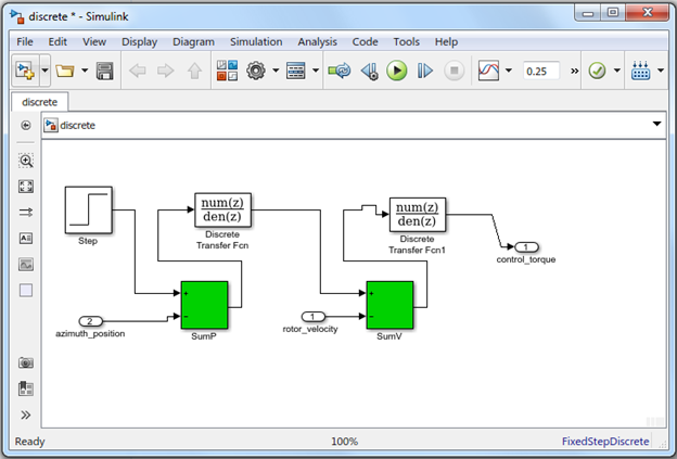
Figure 27 Discrete model
To create the Simulink template for the control system:
1. Enter setio at the MATLAB prompt.
MATLAB creates a template model with the inport(s) and outport(s) defined, as shown in Figure 28.
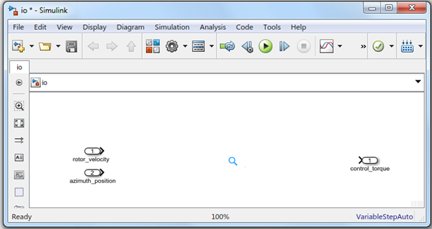
Figure 28 Simulink Template
You can discard this model using the finished discrete.mdl.
Generate S-Function from RTW
Once the Simulink model is created, you will convert this to an S-Function using Code Generation. To do this, the model must be configured properly.
1. In the model discrete.mdl, select Code → C/C++ Code → Code Generation Options.
2. From the treeview on the left side of the window, select Solver.
The dialog box displays the Solver options as shown in Figure 29.
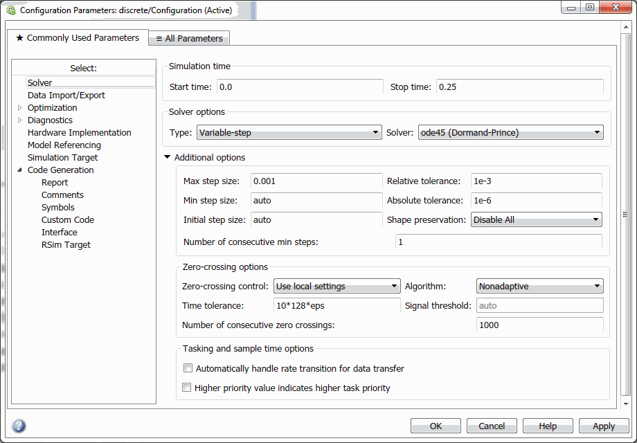
Figure 29 Configuration Parameters
3. Here, under Solver options, Type, select Variable-Step. Any variable-step solver will be fine at this point (for example, ode45), as long as you don't choose a discrete solver for a model with continuous states.
Note: | You can choose either Variable-step or Fixed-step solvers in MATLAB/Simulink. The choice will affect the model code that is generated from RTW, in particular to how sample times are handled. This is important to Adams since Adams will be integrating the model, not MATLAB/RTW. In this regard, the Variable-step integrator is recommended since Adams Solver uses mainly variable-step integrators, and this will ensure the outputs and states are computed properly. If you would still like to use a Fixed-step integrator setting, the model should have at least one continuous state to produce the code for Adams that will handle the sample times properly. For example, if you have a discrete-only model, add a dummy continuous block (for example, Integrator) to the model. |
Tip: | To look for differences in sample times between Fixed-Step and Variable-step integrators settings, look for the function ssIsSampleHit(), which handles evaluation of code at sample times. |
As a MATLAB requirement, an RTW-generated S-Function must have the same type of integrator setting as the model that will use it (that is, both Fixed-step, or both Variable-step).
4. Select Code → C/C++ Code → Code Generation Options. Under Target selection, select Browse and choose the S-Function Target, rtwsfcn.tlc.
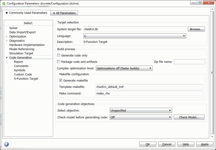
Figure 30 Discrete/Configuration
5. Select Apply to apply your changes, and then select Build to build the S-Function.
You should see messaging in the main MATLAB window about the build process, which should conclude with this message upon a successful build (here, for 64-bit Windows; the extension will depend on the platform):
### Created MEX-file discrete_sf.mexw32
In your working directory, you should find that RTW has created a directory called discrete_sfcn_rtw containing the source files for generating your S-Function, discrete_sf.mexw32.
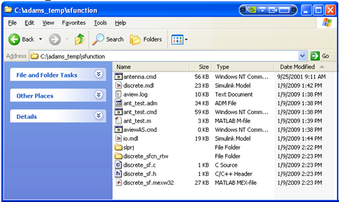
Figure 31 S-Function
6. Furthermore, you should see that RTW created an S-Function block which now supplants your Simulink model (here discrete.mdl):
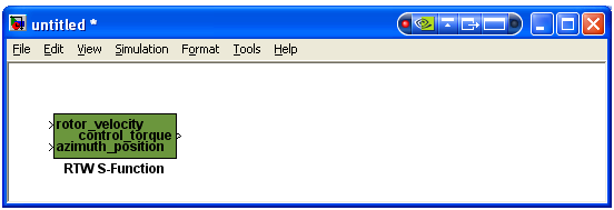
Figure 32 Function block
This is the block to be included in the Simulink model for the Adams External System Library.