Building the Model
In this section, you’ll build a model of the cantilever link. You will build the model by:
Creating the Flexible Link into the Database
In this section, you’ll read the modal neutral file (MNF) containing the flexible link into your model. The flexible link is defined in the file link.mnf in your working directory.
To create the flexible link:
1. Click the Bodies tab on the Adams View ribbon.
2. From the Flexible Bodies container, click the Adams Flex tool  .
.
. The Create a Flexible Body dialog box appears as shown below.
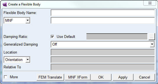
3. Right-click the Modal Neutral File Name text box, and then select Browse.
The File Selection dialog box appears.
4. Select the file link.mnf, and then select OK.
5. Select OK.
A 0.5 meter long flexible link appears in Adams View as shown in the following figure.
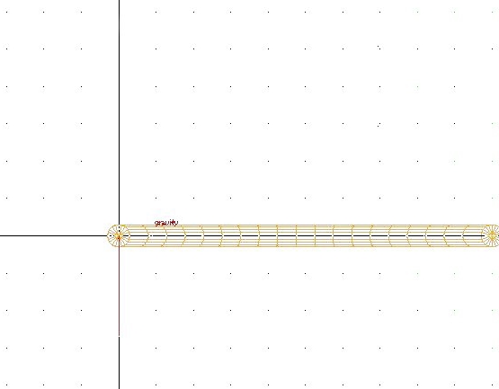
Figure 2 Adams View Screen After Importing the MNF
Adding a Fixed Joint
Now you’ll fix one end of the flexible link to ground using a fixed joint.
To add a fixed joint:
1. Click the Connectors tab on the Adams View ribbon.
2. From the Joints container, click the Fixed Joint tool  .
.
. 3. In the construction container of the Main toolbox, select the construction method 1 Location.
4. Place the cursor at the left end of the link. Node numbers flash on the screen as you move the cursor. Select node 1000 for the location of the fixed joint by clicking the left mouse button when the cursor is over node 1000. Figure 3 shows the location for the fixed joint. Node 1000 is at (0,0,0).
5. If you have trouble selecting the node, try zooming in on the model by pressing either the letter w, to draw a zoom window, or the letter z, to dynamically zoom the window. The window must be active.
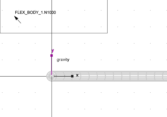
Figure 3 Location to Place Fixed Joint
Creating and Moving a Sphere
Now that you’ve fixed the link to ground, you’ll create a sphere that attaches to the right end of the link. You’ll also move the sphere so its center goes through the center line of the link.
To create and move a sphere:
1. Click the Bodies tab on the Adams View ribbon.
2. From the Solids container, click the Sphere tool  .
.
. 3. Click the left mouse button anywhere in the screen and drag the cursor until you have a sphere approximately 0.3 meters in diameter. (Remember that the length of the link is 0.5 meters.)
4. From the Main toolbar, right click Object Manipulation Strip and select Postion: Move - Translate object (s) tool  .
.
. 5. Following the instructions in the status bar, select the sphere as the object to move. Click near the left edge of the sphere to indicate the point to move from, and then, click on node 1001 at the right end of the link to indicate the point to move to. Press the Ctrl key to use grid points or zoom in on the model to gain greater accuracy.
Figure 4 shows the objects you should select to move the sphere. In the figure, the sphere is located on the left side of the link. The sphere you created could be anywhere in the screen but you still need to select the point on the sphere farthest to the left as the point to move from as illustrated in the figure. The alignment of the sphere with node 1001 does not need to be accurate.
Adams View moves the sphere so its center goes through the center line of the link.
Figure 4 Objects to Select to Move Sphere
Adding a Second Fixed Joint
Your final step in creating the cantilever link is to fix the sphere you created to the link using a fixed joint.
To add a joint:
1. Click the Connectors tab on the Adams View ribbon.
2. From the Joints container, click the Fixed Joint tool .
. 3. In the construction container of the Main toolbox, select the construction method 2 Bod - 1 Loc.
4. Select the link, the sphere, and the end of the link where it coincides with the sphere (FLEX_BODY_1.N1001).
Adams View attaches a fixed joint as shown in the figure below.
You’ll now simulate the model to see how it moves.
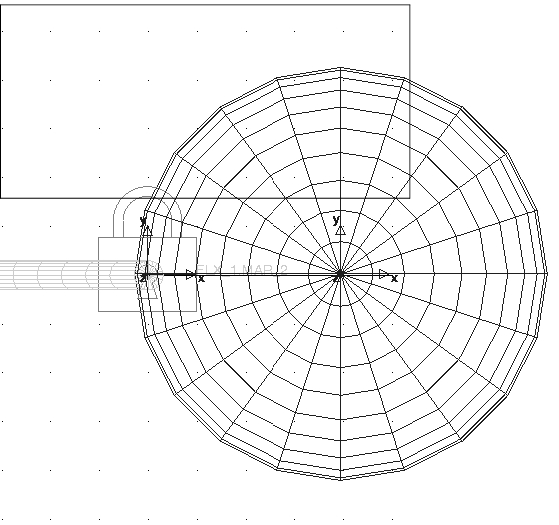
Figure 5 Sphere Connected to Flexible Link