Creating a Cylindrical Worm Gear Pair
In this tutorial, you learn to create cylindrical worm gear pair.
The KISSsoft worm model is exported to the user report file (protocol), the worm and worm gear tooth profiles are generated by KISSsoft and exported to *.txt files. These files are used in Gear AT for shape definition to get worm gear property files (*.wgp) and preprocessed further to get worm gear stiffness files (*.wgs).
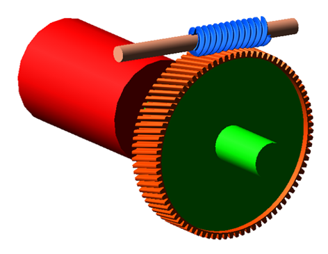
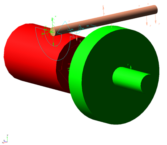
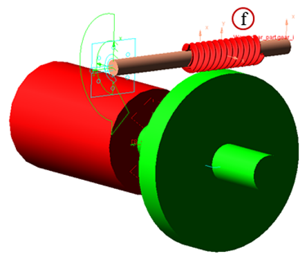
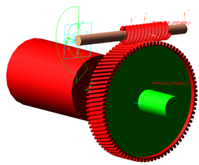
The figure shows the gear pair that you are going to create.
Prepare your working directory
To prepare your working directory:
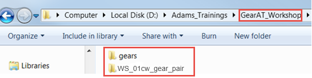
1. Navigate to your working directory in which you create new directory named gears to store all files related to gears.
2. Copy files: Worm_profile.txt, Worm_gear_profile.txt, and Template_protocol.txt from Adams_Install_dir\gear_at\examples\worm to gears directory.
3. Go back to your working directory and create new directory named WS_01cw_gear_pair.
4. Start Adams either from desktop or Windows Start menu → All Programs → Adams 202x.
Opening Start Model
To open an existing start model:
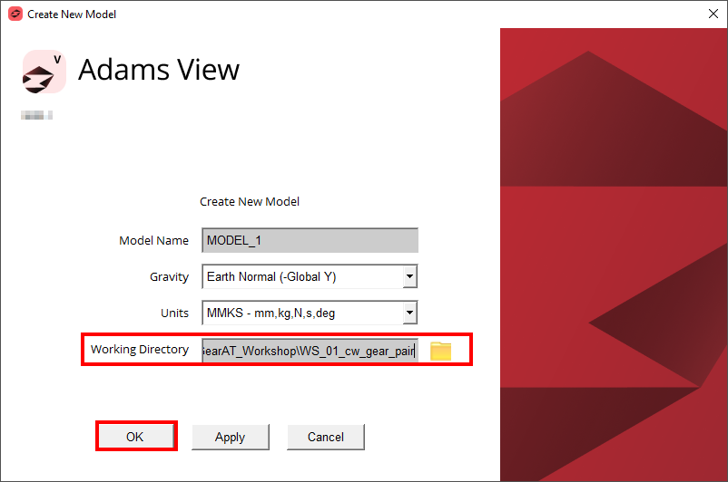
1. Under the Welcome dialog box, select New Model.
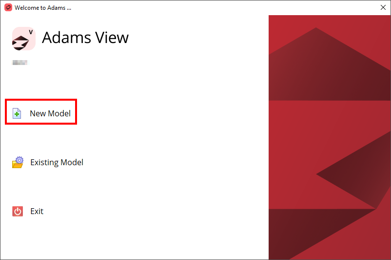
2. Under the Create New Model dialog box, click OK button.
Loading the Workshop Model
To load a Workshop Start Model:
1. Click the Machinery tab on the Adams View ribbon and from the Gear AT container, click the icon to pop up Gear AT menu.
2. In the Menu, select Gear AT → Help → Getting started → Worm gears → Workshop Start Model.
.png)
Creating worm tooth property file using Gear AT Shape Definition
At this point there are no gear property files (*.wgp) available, so we have to prepare them from scratch. In this step we define a property file by input files from KISSsoft, Profile file (*.txt) and Protocol file (*.txt) which contain all geometrical parameters of a worm and worm wheel tooth geometry.
Note: | For details about how to export the relevant files from Kisssoft, refer to Export KISSsoft Data section. |
To create the worm tooth property file:
1. In the Gear AT menu, select Cylindrical Worm Gear → Gear AT Preprocess → Gear AT Shape Definition Worm Cylindrical.
.png)
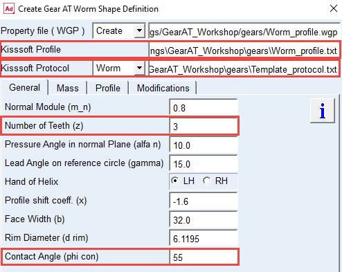
2. In the Kisssoft Profile, right click and Browse the ../gears directory for the: Worm_profile.txt (name of property file is automatically filled up, but you can change this name as required).
3. In the Kisssoft Protocol, right click and Browse the ../gears directory for the: Template_protocol.txt.
4. Set the option menu to “Worm”; make sure that the value of Number of Teeth is set to 3.
5. Enter the value of Contact Angle: 55.
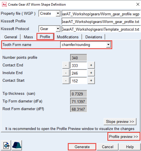
6. Select the Profile tab.
7. Click the Profile preview button to review the tooth profile, check key points on profile.
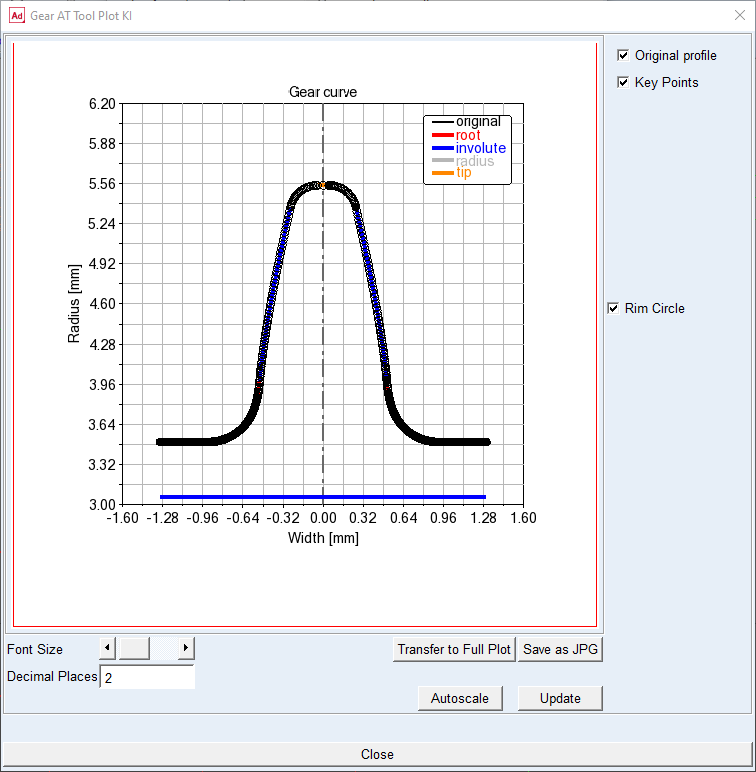
8. Check the Tooth Form name option menu, and make sure that the chamfer/rounding manufacturing step is selected.
9. Click the Generate button.
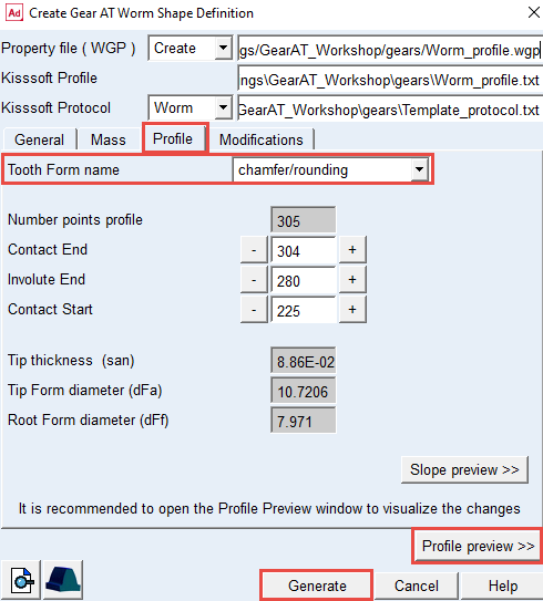
10. The Worm_profile.wgp file is created in the ../gears directory. Click the Cancel button to close the Gear AT Shape Definition dialog box.
Meshing worm tooth using Gear AT Mesh
In this step we preprocess FE mesh of a flexible tooth based on profile stored in a *.wgp file and generate shell file for Adams geometrical representation. Hereafter the stiffness matrix of a flexible tooth is generated with the help of Nastran embedded solver in Adams which is stored in *.wgs file located in the gears folder. It will be referenced for the gear pair contact force definition later on.
To create Nastran mesh and the geometry of the worm:
1. In the Gear AT menu, select Cylindrical Worm Gear → Gear AT Preprocess → Gear AT Mesh.
.png)
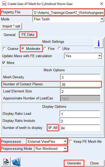
2. In the Property File, right click and Browse the ../gears directory for the: Worm_profile.wgp.
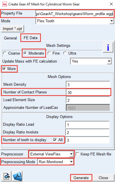
3. Select the FE Data tab.
4. Select the option Moderate mesh.
5. Select the More toggle for more options.
6. Enter the Number of Contact Planes: 30.
7. In the Display options, make sure to select All for the Number of teeth to display toggle.
8. Select the Preprocessor: External ViewFlex.
9. Select the Preprocessing Mode: Run Monitored.
10. Click the Generate button, click YES to confirm the start of preprocessing and wait till the SOL101 is completed.
Creating worm wheel tooth property file using Gear AT Shape Definition
To create the worm gear tooth property file:
1. In the Gear AT menu, select Cylindrical Worm Gear → Gear AT Preprocess → Gear AT Shape Definition Worm Cylindrical.
2. In the Kisssoft Profile, right click and Browse the ../gears directory for the: Worm_gear_profile.txt (name of Property File is automatically filled up, but you can change this name as required).
3. In the Kisssoft Protocol, right click and Browse the../gears directory for the: Template_protocol.txt.
4. Set the option menu to Gear; make sure that the value of Number of Teeth is set to 84.
5. Enter the value of Contact Angle: 4.
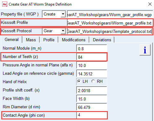
6. Select the Profile tab.
7. Click the Profile preview button to review the tooth profile, check key points on profile.
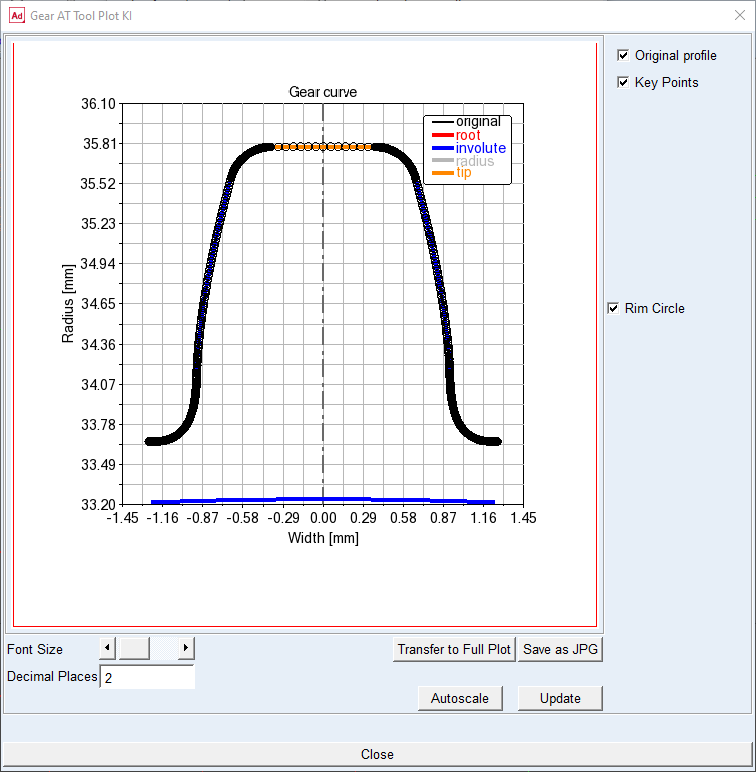
8. Check the Tooth Form name option menu, and make sure that the chamfer/rounding manufacturing step is selected.
9. Click the Generate button.
10. The Worm_gear_profile.wgp file is created in the ../gears directory. Click the Cancel button to close the Gear AT Shape Definition dialog box.
Meshing worm wheel tooth using Gear AT Mesh
To create Nastran mesh and the geometry of the worm:
1. In the Gear AT menu, select Cylindrical Worm Gear → Gear AT Preprocess → Gear AT Mesh.
2. In the Property File, right click and Browse the ../gears directory for the: Worm_gear_profile.wgp.
3. Select the FE Data tab.
4. Select the option Moderate mesh.
5. Select the More toggle for more options.
6. Enter the Number of Contact Planes: 30.
7. In the Display Options, make sure to select All for the Number of teeth to display toggle.
8. Select the Preprocessor: External ViewFlex.
9. Select the Preprocessing Mode: Run Monitored.
10. Click the Generate button, and click the YES to confirm the start of preprocessing and wait till the SOL101 is completed.
Creating Worm Gear AT Element
To create Worm Gear AT Element:
1. In the Gear AT, select Cylindrical Worm Gear → Gear AT Element → Gear AT Worm Element → New.
.png)
2. Enter the Gear Name: Worm.
3. In the Property File, right click and Browse the ../gears directory for the: Worm_profile.wgp.
4. In the Ring Gear Reference Marker, right click and Browse for the ref_worm, which belongs to the worm_shaft part.
5. Click the Apply button.
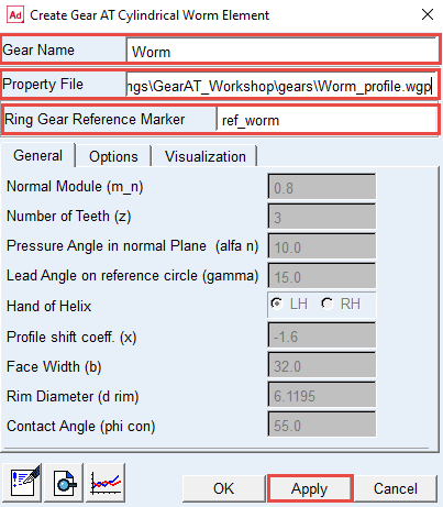
6. The Worm Gear AT Element has been created
Creating Worm Wheel Gear AT Element
To create Worm wheel Gear AT Element:
1. In the Gear AT menu, select Cylindrical Worm Gear → Gear AT Element → Gear AT Worm Wheel Element → New.
.png)
2. Enter the Gear Name: Worm_wheel.
3. In the Property File, right and click Browse the ../gears directory for the: Worm_gear_profile.wgp.
4. In the Ring Gear Reference Marker, right click and Browse for the ref_wheel, which belongs to the wheel_shaft part.
5. Click the OK button.
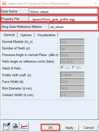
6. The Worm wheel Gear AT Element has been created.
Creating Gear AT Contact Force for cylindrical worm gear pair
Theory – Damping Force
The function b defined by:
b = 1.0 - gap / (2*oil film thickness)
is used to smooth the damping.
There is no hydrodynamic damping, when b < 0:
F hyd = 0 for b<0
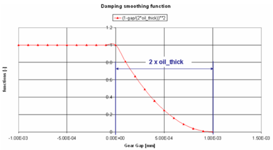
Hydrodynamic damping increases exponentially with decreasing oil film height. The introduction of the damping exponent d_exp:
F hyd = damp rate oil * squeeze vel * vel bd_exp for 0>b>1
is used for this purpose (see Figure 1).
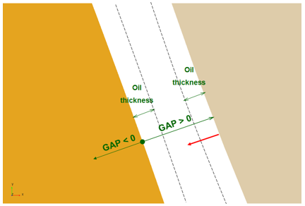
Figure 1 Oil Film Thickness
The structural damping force is made proportional to the contact force as shown by:
F struc damp = F cnt * Damp structure * sign (squeeze vel)
A value of 0.01 means, that the structural damping force is 1.0 percent of the elastic contact force.
Theory – Friction Force
The static friction coefficient ( s) is usually somewhat higher than the dynamic friction (
 d) coefficient. Step functions are used for smoothing the transitions (Figure 2). Parameter of slip velocity (Vs) limits the region of sign change of the sliding velocity.
s) is usually somewhat higher than the dynamic friction (d) coefficient. Step functions are used for smoothing the transitions (Figure 2). Parameter of slip velocity (Vs) limits the region of sign change of the sliding velocity.The combination of very small slip velocity (Vs) and high friction can reduce the performance of the integrator. You are advised to validate this selection through postprocessing of the sliding velocity.
Transition velocity (Vd) defines the start of the region, where the dynamic friction is constant. A small difference between slip velocity (Vs) and transition velocity could (Vd) also lead to numerical issues of the integrator.
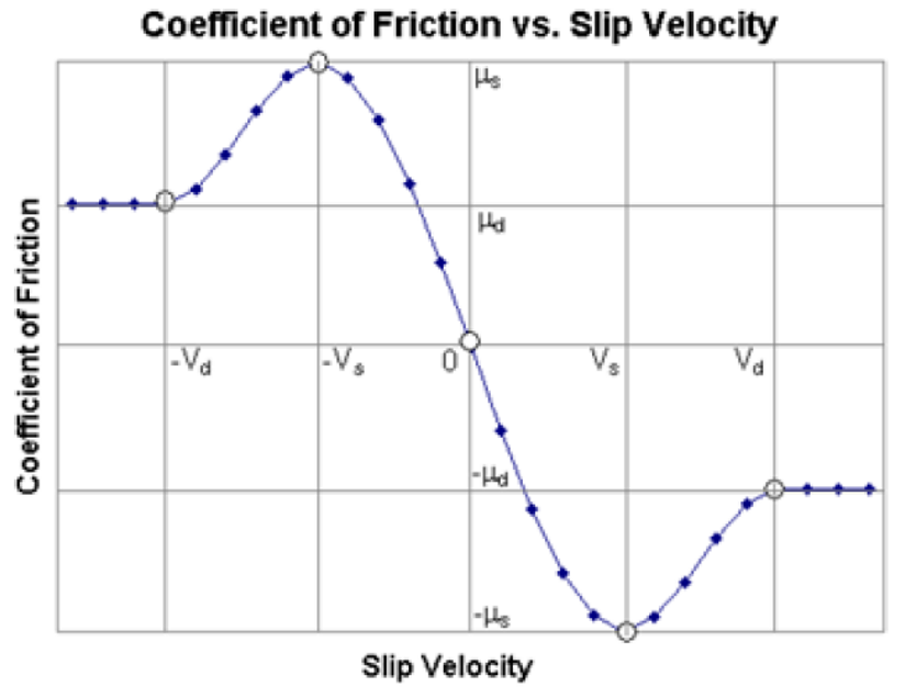
Figure 2 Friction vs. Slip Velocity
Creating Gear AT Contact Force for cylindrical worm gear pair
To create gear contact force for the gear pair:
1. In Gear AT menu, select Cylindrical Worm Gear → Gear AT Force → New.
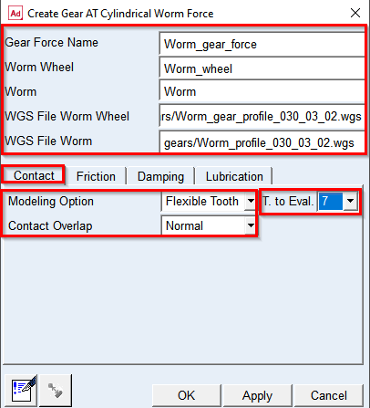
.png)
2. Enter the Gear Force Name: Worm_gear_force.
3. Select the Worm Wheel: Worm_wheel.
4. Select the Worm: Worm.
5. In the WGS File Worm Wheel, right click and Browse the ../gears directory for the: Worm_gear_profile_030_03_02.wgs.
6. In the WGS File Worm, right click and Browse the ../gears directory: Worm_profile_030_03_02.wgs
7. Set Modeling Option to Flexible Tooth.
8. Set number of teeth to evaluate in contact T.to Eval. to value 7.
9. Set Contact Overlap to Normal.
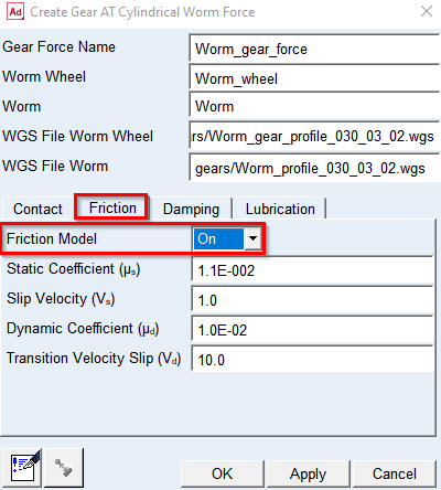
10. Go to Friction tab.
11. Set the Friction Model to ON.
12. Go to Damping tab and enter the Damping Rate Oil: 10.0.
13. Click the OK button.
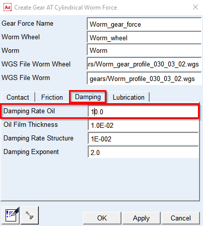
14. The Gear AT Force has been created.
Completed cylindrical worm gear model
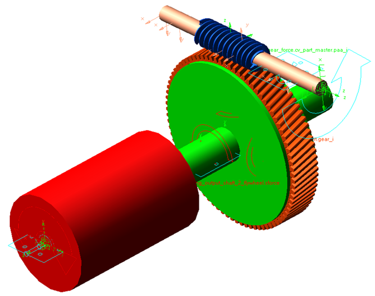
Note: | The color of the Worm and Worm_wheel Gear AT Element has changed. The color coding is set according to the role of a gear. |
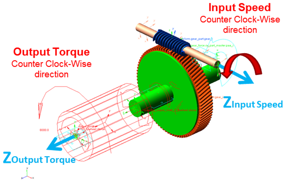
Setup Input motion and Output torque
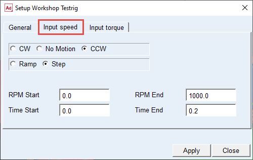
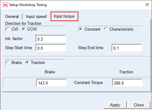
Before running simulation make sure that values of following testrig parameters are set as shown thus the driving motion function steps up from 0 to 200 rpm and the output torque steps up from 10% to 100% of 2.5e5 Nmm. In this workshop model the output torque is defined from perspective of input, hence the torque value has to be divided by the gear ratio (3.521).
1. In the Gear AT menu, select Help → Getting Started → Setup Workshop Testrig.
.png)
2. Go to Input speed tab and set the driving motion parameters as shown in figure below.
3. Go to Input torque tab and set the loading torque parameters as shown in figure below.
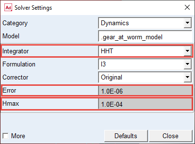
Set the Solver Settings
To set the solver settings:
1. In the Menu, select Settings → Solver → Dynamics.
.png)
2. Select the Integrator: HHT.
3. Enter the Error: 1.0E-06.
4. Enter the Hmax: 1.0E-04.
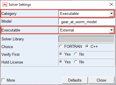
5. Change the Category to: Executable.
6. Set the Executable to: External.
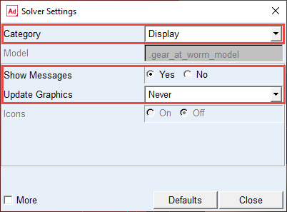
7. Change the Category to: Display..
8. Set the Show Messages to: Yes.
9. Set the Update Graphics to: Never
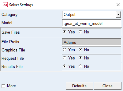
10. Select Category: Output.
11. Set the Save Files: YES.
12. Set the File prefix: Adams; this will be used for WGR result files for contact pattern post-processing.
13. Set the Graphics File: NO.
14. Set the Request File: NO.
15. Set the Results File: YES.
16. Select Category: Equilibrium.
17. Select the More options.
18. Enter the Tlimit: 0.01.
19. Enter the Alimit: 0.01.
20. Enter the Maxit: 250.
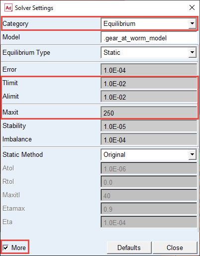
Note: | Using default solver settings for static equilibrium could result in failure to reach convergence for static and quasi-static simulation. |
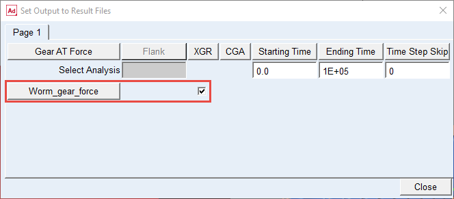
Verifying Worm Gear_AT Results Output Settings
Before you start the simulation, make sure the output of WGR files is switched on, to be able to make contact pattern post-processing:
1. In the Gear AT menu, select Cylindrical Worm Gear → Gear AT Results → Output Settings.
.png)
2. Verify that the XGR toggle for Worm_gear_force is switched on.
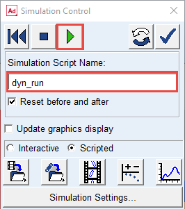
Verify simulation script and run the simulation
To verify the simulation script and run the dynamic simulation:
1. In the Model Browser double click on Simulations, right click on dyn_run and select Modify.
2. Verify the Solver Script and click OK button.
.png)
3. In the Simulation tab, select Run a Scripted Simulation.
4. Select the Solver Script: dyn_run.
5. Push the Play button to start the simulation. The simulation will take a few minutes to run.
Investigate the simulation results
In the Adams Postprocessor, you can investigate the simulation results.
Make plot of Wheel wheel and Worm torque applied around its rotational axes:
Note that Force and torque vectors refer to so called Contact Coordinate System (CCS):
1. Switch to Adams Postprocessor (press F8 on keyborad).
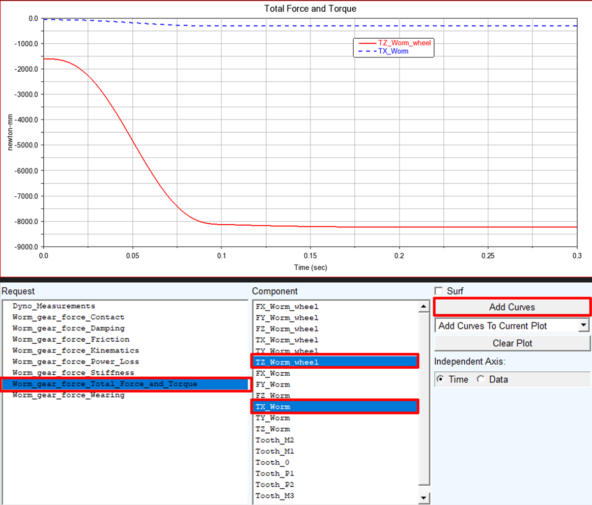
2. Select the Source: Requests.
3. Select the Request: Worm_gear_force_Total_Force_and_Torque.
4. Select the Components: TZ_Wheel and click Add Curves button.
5. Select the Components: TX_Worm and click Add Curves button.
Note: | The resulting force and torque vectors are measured in so-called contact coordinate system denoted by “c” index on the Figure 3. In the Total Force and Torque request group the vectors represent sum of all components from contact stiffness, damping and friction. However, one can plot each component of total force or torque separately. For more information, refer Gear AT Results 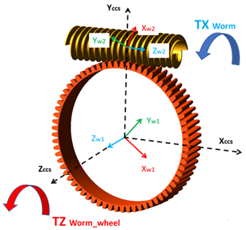 Figure 3 Gear_AT_Worm_gear_contact_co-ord_sys |
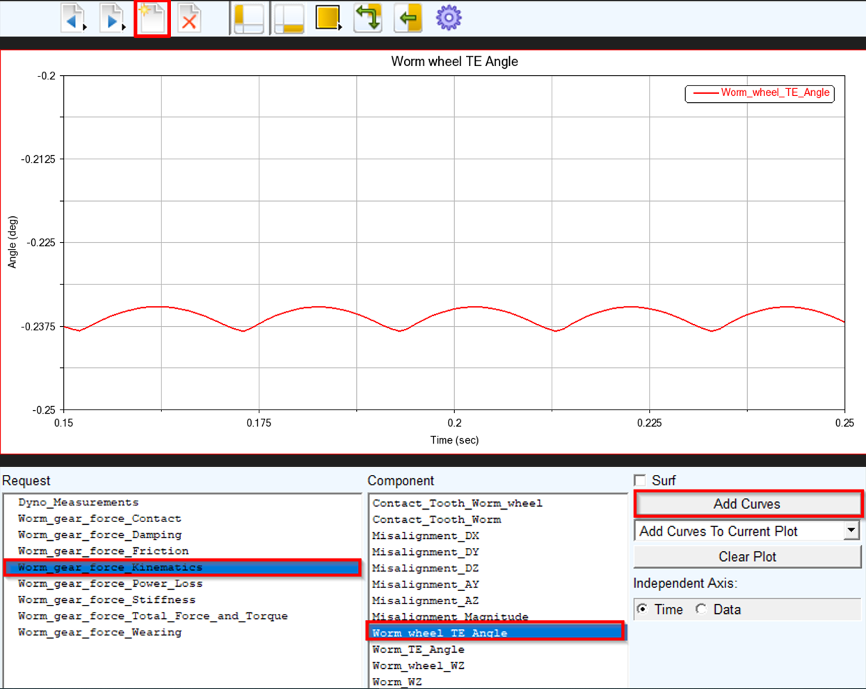
Make plot of Worm Wheel Transmission Error and create FFT plot to identify the tooth mesh frequency:
1. Create a new page
2. Select the Request: Worm_gear_force_Kinematics.
3. Select the Component: Worm_Wheel_TE_Angle and click Add Curves button.
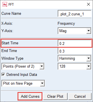
4. In the Menu, select Plot → FFT.
5. Select Detrend Input Data toggle.
6. Set the Start Time: 0.2.
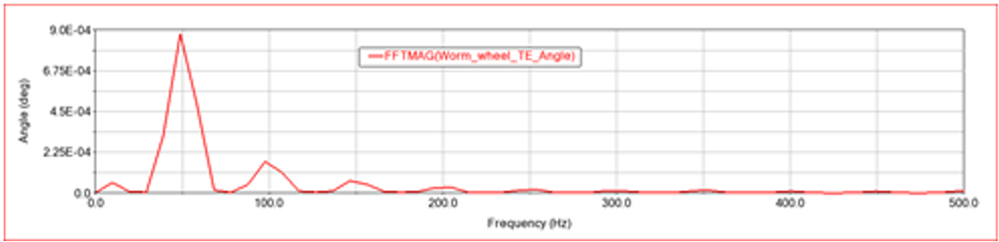
7. Click the Add Curves button.
8. The FFT plot is created. Zoom the horizontal axis from 0 to 500 Hz.
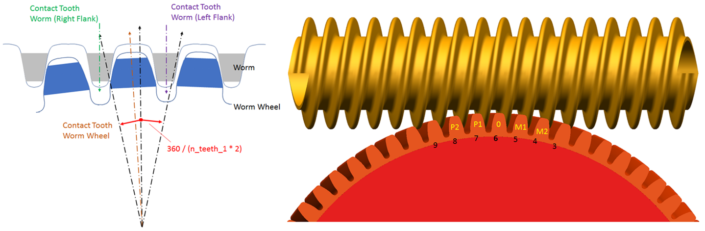
Theory – Teeth Numbering convention
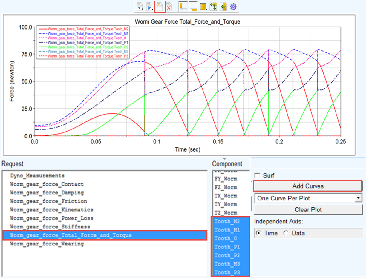
To plot tooth force magnitude applied on all teeth in contact:
1. Switch to Adams Postprocessor (press F8 on keyborad).
2. Select the Source: Requests.
3. Select the Request: Worm_gear_force_Total_Force_and_ Torque.
4. Select the Components: Tooth_M3 : Tooth_P3 and click Add Curves button.
5. Zoom in the plot as appropriate.
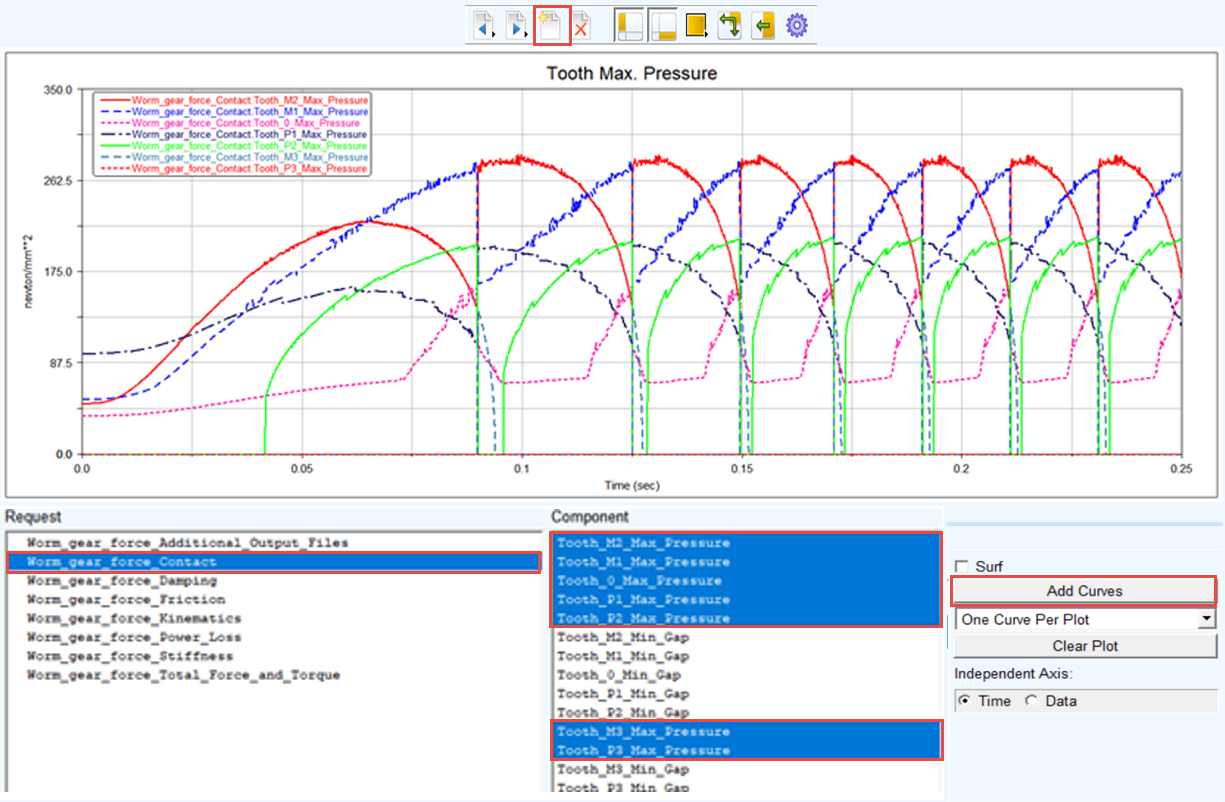
Make plot of maximum contact pressure over all teeth in contact:
1. Create a new page
2. Select the Request: Worm_gear_force_Contact.
3. Select the Component: Tooth_M3_Max_pressure: Tooth_P3_Max_pressure and click Add Curves button.
4. Zoom in the plot as appropriate.
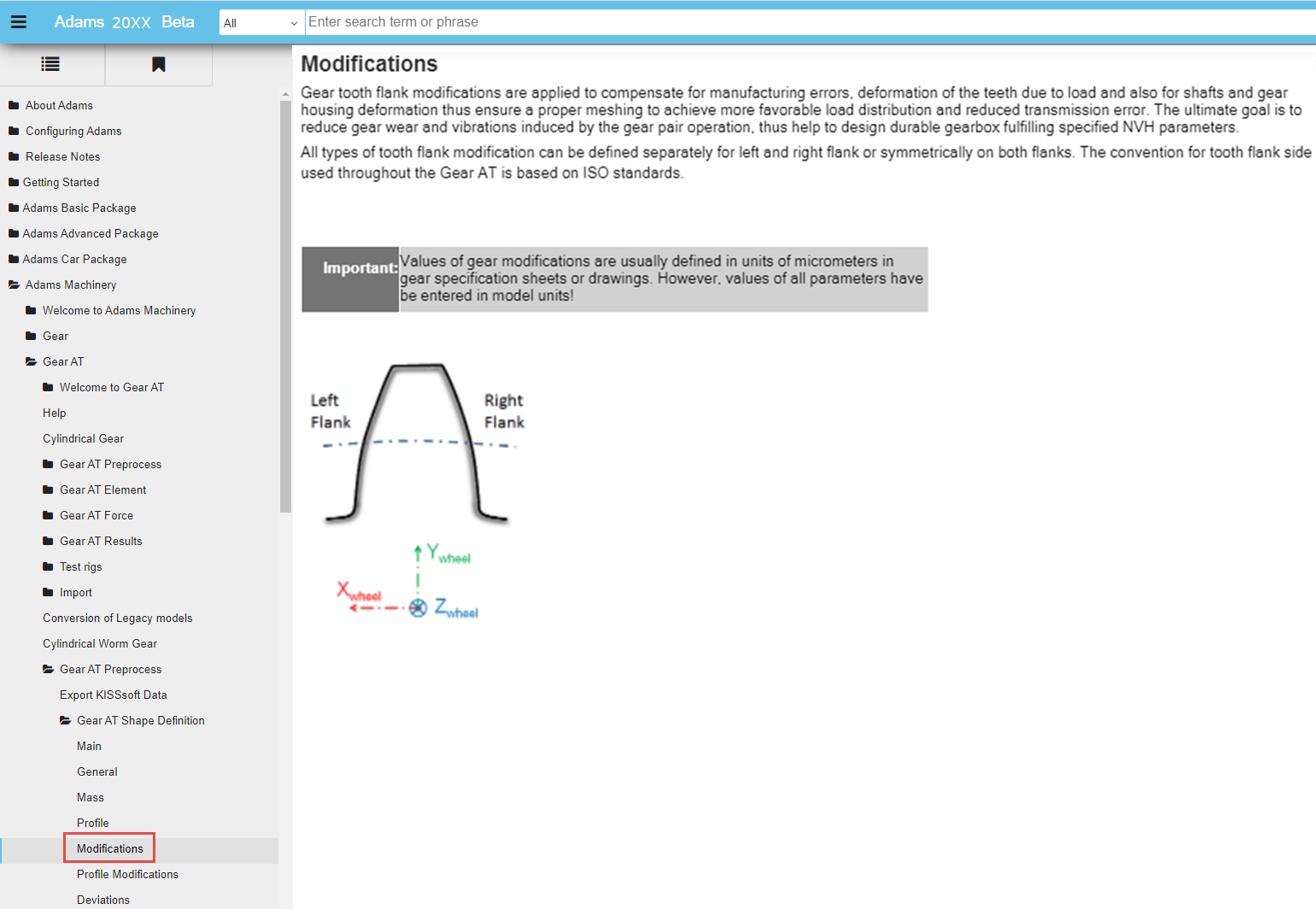
Theory – Tooth flank side definition
Before plotting the contact pattern we need to find out the tooth in contact at particular time interval of interest.
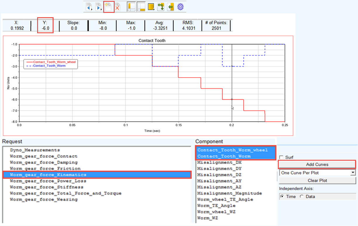
To plot the worm and worm gear contact tooth:
1. Create a new page.
2. Select the Request: Worm_gear_force_Kinematics.
3. Select the Component: Contact_Tooth_Worm and Contact_Tooth_ Worm_wheel, click Add Curves button.
4. In the Menu bar, select the Plot tracking. Track the value of Worm_Wheel contact tooth close to time of 0.2 sec. From the tracking plot panel we can see that Y value is equal to -6. This indicates the number of Worm_Wheel tooth on which the contact pressures can be displayed at the given time interval and that the side of contact is Right (MINUS) tooth flank.
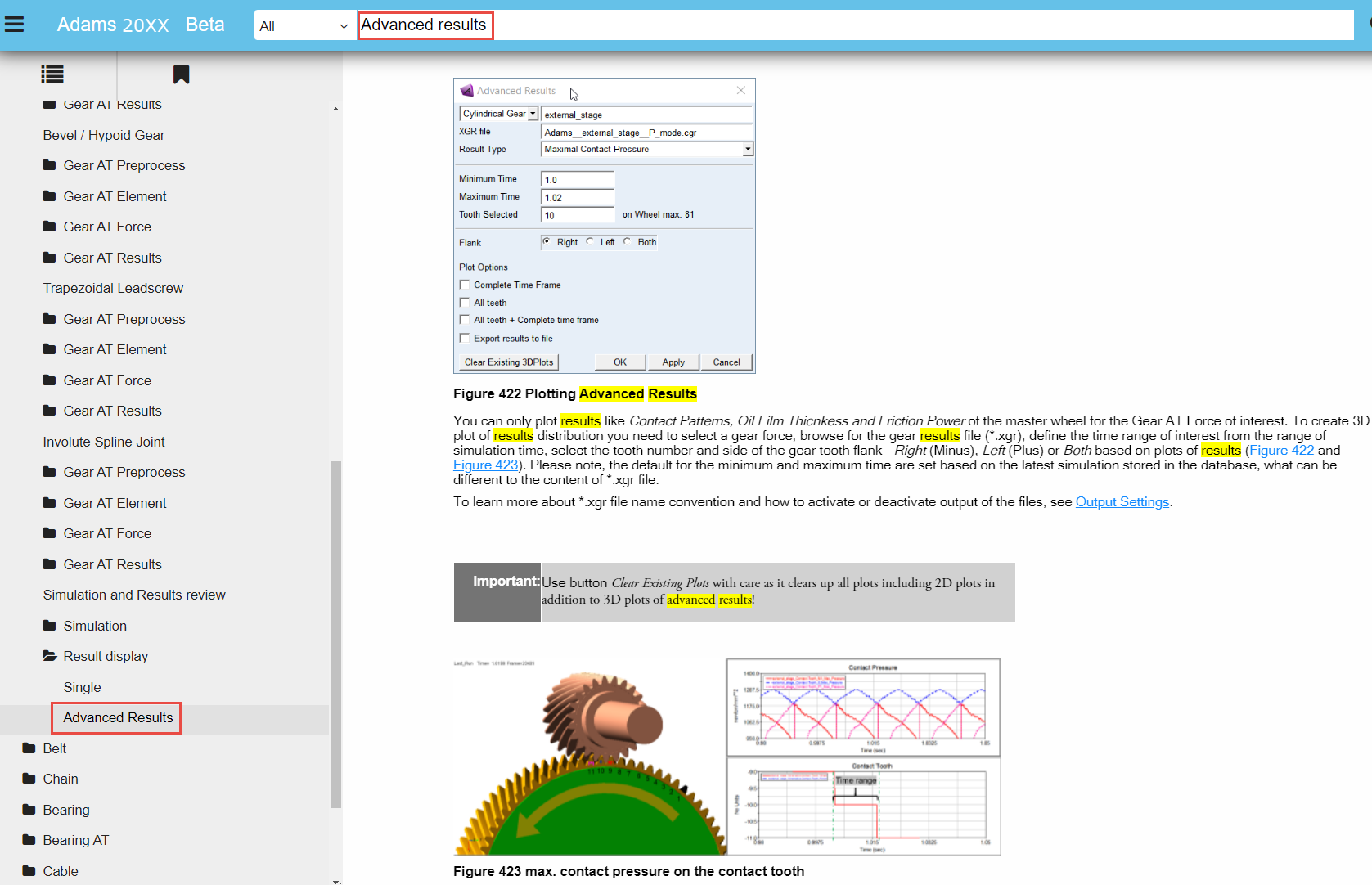
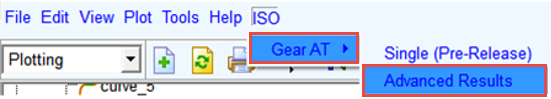
To plot the contact pattern in the Adams Postprocessor:
1. In the Adams Postprocessor menu, select ISO → Gear AT → Advanced Results.
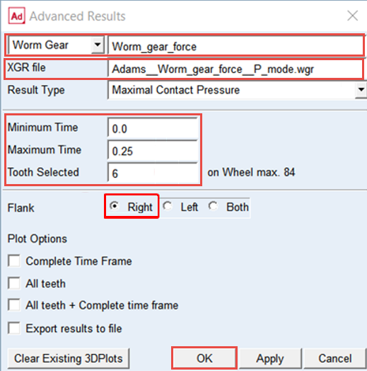
2. Select the Worm Gear: Worm_gear_force.
3. In the XGR, right click and Browse the working directory ../gears for the file: Adams__Worm_gear_force__P_mode.wgr (it does not matter which one of two files is selected, the both are loaded).
4. Set values for Minimum Time and Maximum Time: 0.0 and 0.25 respectively.
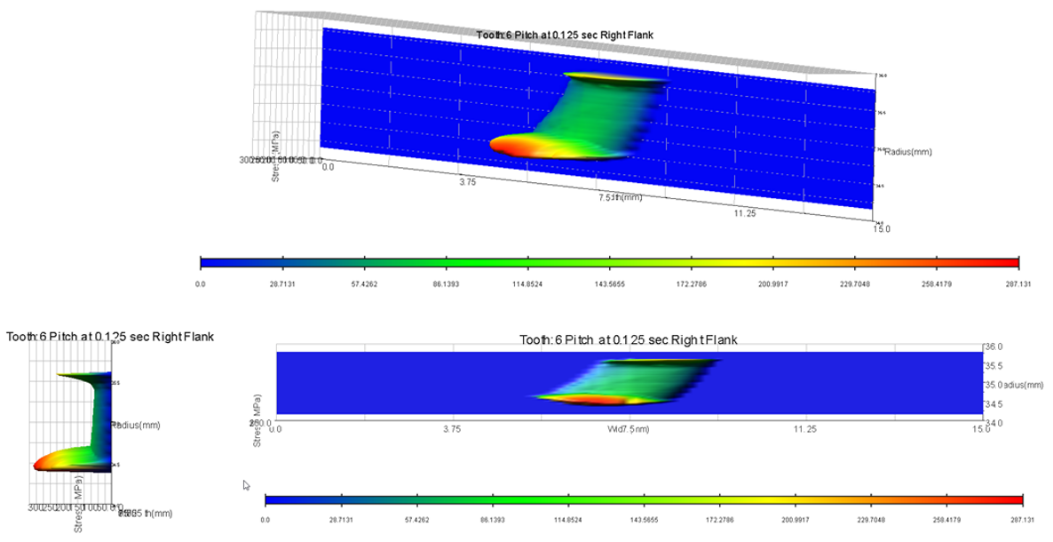
5. Set the Tooth Selected: 6.
6. Set the Flank button to Right for the contact flank (Right=Minus contact mode – Worm_Wheel contact tooth = -6.0).
7. Click OK button.
8. The plots of the contact pattern results are created.
9. Explore contact pattern of the Right contact flank of Tooth 6.
10. Rotate the view to see the contact pattern from different views.
Save your work
This concludes the workshop, save your work before exit.
To save your model:
1. Switch to Adams View (press F8 on keyboard).
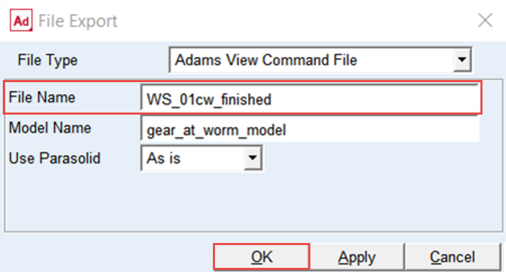
2. In the Menu, select File → Export.
3. Select the File Type: Adams View Command File.
4. Enter File Name as WS_01cw_finished.
5. Click the OK button.
6. The CMD file is exported to your working directory. You can use it in the next workshop.