Defining Attachment Points in Parametric Extrusions
To define attachment points on parametric extrusions:
1. In the ViewFlex dialog box, set FlexBody Type to Extrusion.
2. Select Attachments.
A row appears for entering the data required to define the extrusion's attachment points, as shown in the figure below. Each row in the data table represents the characteristics of a single attachment point.
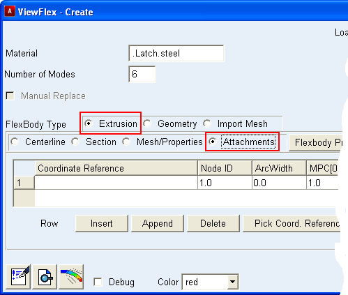
3. Define an attachment by entering values in the columns of the current row.
For the column: | Do the following: |
|---|---|
Coordinate Reference | Enter the name of the marker whose location defines the location of the attachment point. Adams ViewFlex will store its Cartesian coordinates for future use. It does not display the location of the attachment points to prevent modification; therefore, preserving them for parameterization. Note: The coordinate references are accepted only if they belong to the ground part. If you do not enter an existing coordinate, the flexible body creation process fails, and Adams ViewFlex displays the following message: One or more invalid coordinate references selected. Please check. |
Node ID | Identifier number of the flexible body node to be defined as an attachment point. This option helps you find the attachment nodes and distinguish them from the other nodes defining the flexible body. |
ArcWidth | Diameter to define a sphere that will be centered on the primary centerline point (C. Point). Adams ViewFlex considers any nodes within the sphere as secondary nodes of the attachment point. The larger the diameter, the more secondary nodes you select, as shown in the two figures below. Examples of Different Diameters for ArcWidth 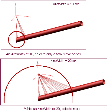 |
MPC[0.1] | Percentage of each section's nodes that are connected to the attachment point (0 < MPC <= 1). If percentage value is less than 1, the section points closest to the attachment points are connected. Increasing the percentage value results in a larger number of nodes being connected to the attachment point. ■MPC(0.1) = 1 100% of nodes will be attached ■MPC(0.1) = .5 50% of nodes will be attached |
C. Point | One of your centerline reference markers to define a plane of nodes that you will use as secondary nodes for the desired attachment point. C.Point=0 means that the attachment point will choose the closest centerline reference marker. Examples of Defining C.Point 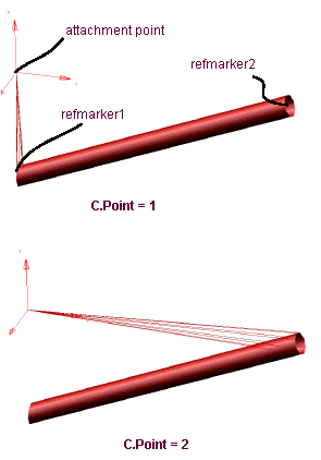 |
Rel. DOF | Degrees of freedom (DOF) to be released in the modal analysis. Any released DOF do not allow constraints with other bodies. The required input is a series of integers, from 1 to 6, indicating that the corresponding DOF must be released. If 0 is entered, no DOF is released. Entries produce the following results: ■1 = X-axis translation ■2 = Y-axis translation ■3 = Z-axis translation ■4 = X-axis rotation ■5 = Y-axis rotation ■6 = Z-axis rotation For example, if you want to release x translation, z translation, and y rotation, enter 135. To release all rotational DOF, enter 456. |
4. To create new rows in order to define more attachment points, see Working with the ViewFlex Dialog Box.