Defining Attachment Points in Existing Solid Geometry
To activate the attachment point definition window for flexible bodies created using the Geometry Method:
1. In the ViewFlex dialog box, set FlexBody Type to Geometry.
2. Select Attachment as shown below.
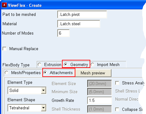
Note: | If you haven't defined a mesh preview using Mesh Preview, ViewFlex creates it based on default or user defined mesh parameters. Text boxes and cells in which to define attachment points for the flexible generic geometry appear, as shown in the figure above. Each row in the data table represents the characteristics of a single attachment point. |
3. Select Find Attachments to have ViewFlex find the existing attachment points (location of joints, constraints, forces) of a rigid body which is connected to a mechanical system. If ViewFlex finds no attachments, the following message appears:
Attachments auto detection process failed.
4. If no attachment points exist, define an attachment by entering values in the columns.
For the column: | Do the following: |
|---|---|
Coordinate Reference | The location of the attachment point. Enter a coordinate reference marker to get its Cartesian coordinates. Adams ViewFlex defines the attachment point at that location. If a marker does not exist at the entered location, Adams ViewFlex automatically creates a new marker, belonging to the ground part, at the specified location. Note: The coordinate references are accepted only if they belong to the ground part. |
Node ID | Identifier number of the flexible body node to be defined as an attachment point. This option helps you find the attachment nodes and distinguish them from the other nodes defining the flexible body. |
Rel. DOF | Degrees of freedom (DOF) to be released in the modal analysis. Any released DOF do not allow constraints with other bodies. The required input is a series of integers, from 1 to 6, indicating that the corresponding DOF must be released: ■0 = No DOF released ■1 = X-axis translation ■2 = Y-axis translation ■3 = Z-axis translation ■4 = X-axis rotation ■5 = Y-axis rotation ■6 = Z-axis rotation For example, if you want to release x translation, z translation, and y rotation, enter 135. To release all rotational DOF, enter 456. |
5. To create new rows to define more attachment points, refer to Working with the ViewFlex Dialog Box.