Defining Nodes at the Attachment Points
To define nodes to connect to each attachment point using either the Geometry or the Import Mesh Method, the options given on the right side of the ViewFlex dialog box can be used. These data input options are related to the number of defined attachment points. There is one text box for each attachment point, which can be selected and opened by choosing the respective table row.
Attachment nodes can be selected using one of five methods. Click on a method to learn more:
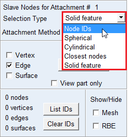
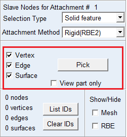
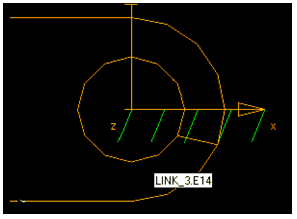
Parasolid features
Automatically finds nodes belonging to Parasolid objects (vertex, edge, surface) of the selected geometry. Using Pick you can select the nodes belonging to the parasolid features.
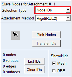
Direct node selection (only when applying the Geometry Method)
Manually select the desired nodes from your model.
Spherical scanning
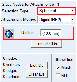
Selects all nodes within a given radius of the attachment point. Enter a value for Radius. You should transfer the IDs before creating the flex preview or final MNF.
Cylindrical scanning
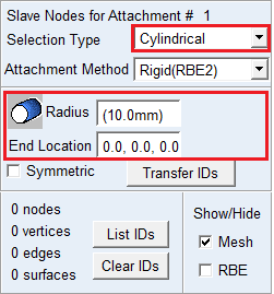
This method selects all nodes within a given cylindrical region. The user has to provide the end point of the cylinder and the radius.
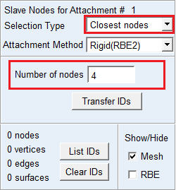
Automatic Node Selection
Automatically finds a set number of nodes that are closest to the attachment points.
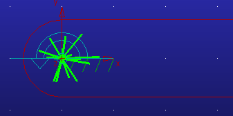
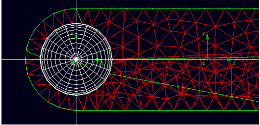
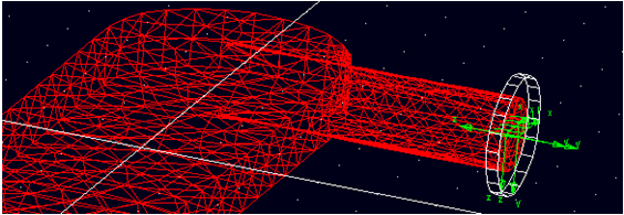
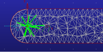
Rigid Body Element (RBE) Preview
All attachment nodes connected by RBE can be previewed before flexible body generation by clicking on RBE toggle button. Some nodes have to be transferred by Transfer IDs push button in advance.
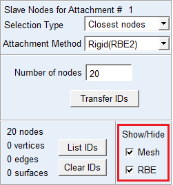
RBE can be shown in colored and highlighted spider web.
Mesh Preview can be hidden by clicking off Mesh toggle button.