Creating Flexible Bodies from Imported External Meshes
An external mesh (BDF or DAT format) can be imported into ViewFlex to generate a flexible body.
After importing the mesh, you can set all the options for elements properties, attachments, and secondary nodes to create the flexible body.
Accessing Import Mesh Method Options
To access the Import Mesh Method options:
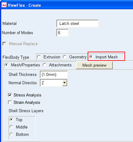
In the ViewFlex dialog box, set FlexBody Type to Import Mesh.
The options in the ViewFlex dialog box change to those for working with importing an external mesh. The upper portion lets you select the mesh file, and the lower portion lets you define mesh properties.
Selecting Mesh File Name
The following explains how to import the external mesh file when creating a flexible body using the Import Mesh Method.
To import the external mesh file:
■Enter a file name containing the mesh description into the Mesh File Name text box.
Previewing Mesh
To preview a mesh of the selected geometry when using the import mesh method:
■Select Mesh Preview.
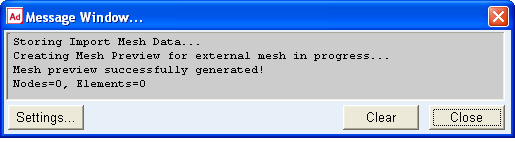
ViewFlex generates a preview of the imported mesh. After mesh preview generation, 'Delete Mesh Preview' is automatically selected to delete the previously generated mesh.
The steps performed by ViewFlex, during mesh creation, can be followed in the Message window.
Defining Mesh Properties
Mesh properties like number of modes, shell thickness and material type of a flexible body can be set using the import mesh method.
To define the mesh:
From the ViewFlex dialog box, select Mesh/Properties option for setting the mesh appear.
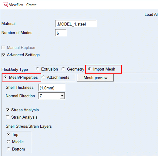
Set mesh properties:
■Number of Modes: Enter the number of dynamic modes required for a modal analysis. This option sets the accuracy for dynamic description of the flexible body (frequency content).
■Shell Thickness: Enter the thickness of shell elements for computing mass and stiffness properties.
■Material: Enter type of material to consider in evaluating the structural properties of the flexible body.
Activate Stress/Strain Calculation
You can select a stress and/or strain calculation as you create a flexible body using the import mesh method. It is available for both shell and solid elements. For shell elements, you can define the surface (top, middle, or bottom) on which you want the stress/strain calculated. To view the stress/strain in Adams Postprocessor, you must have Adams Durability installed on your computer.
To calculate the stress/strain:
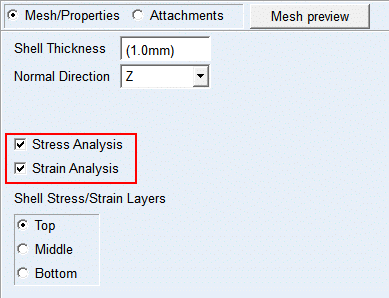
■While defining the mesh and material properties, from the ViewFlex dialog box, select Stress Analysis and/or Strain Analysis, as shown below.
■For shell elements, under Stress/Strain Analysis, select the layer on which you want the stress/strain calculated.
Limitations of Imported Mesh
■The file should only contain nodes and elements (other cards will be filtered and neglected).
■The mesh must only be defined by selected types of elements: for shell, CTRIA3 or CTRIA6; for solid, CTETRA.
■There can only be one type of element (shell or solid) present at a time.
■The external mesh must not contain the attachment points, which means that it cannot contain rigid elements: RBAR, RBE2, and RBE3.
■Attachment nodes and secondary nodes will be defined through the ViewFlex dialog box.
■MAT card or Element property cards will be neglected. Therefore, element properties and material will be defined through the ViewFlex dialog box.