Advanced Setup for Time Domain Simulation
If the "Time Domain" menu option was chosen, then the Advanced Setup area contains the following inputs:
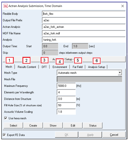
The Advanced Setup area consists of the following tabs
1. Mesh
2. Results Content
3. DFT
4. Environment
5. Far Field
6. Analysis Setup
Mesh Tab
The Mesh Tab allows creation of the acoustic mesh utilized for the acoustic radiation of the vibrating structure. The inputs are described below. See the Mesh section of the Appendix for more details.
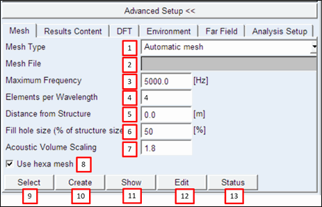
In the mesh tab one can define:
1. Mesh Type, in this combo box one can chose between
■Mesh already provided: Choose this option if the full acoustic mesh is already created and available (see Full Acoustic Mesh in Appendix).
■Shrinkwrap provided: Choose this option if the shrinkwrap of the structure is available, but not the surrounding 3D mesh. A shrinkwrap is a smooth 2D element surface surrounding the structure, but not sharing nodes with the structural nodes. The shrinkwrap should be provided if the automatic mesh fails or doesn't give convenient results.
■Automatic mesh: This option can be chosen to automatically generate the acoustic mesh. In most of the cases mesh creation will be successful. In case that the Automatic mesh is not successful, one should manually create the shrinkwrap mesh and supply that here.
2. Mesh File: Browse for and specify the mesh file if either "Mesh already provided" or "Shrinkwrap provided" are chosen for Mesh Type.
3. Maximum Frequency: Defines the maximal frequency that should be supported by the acoustic mesh. The higher the frequency, the finer the acoustic mesh will become because the acoustic wavelength will be used for the mesh criteria.
4. Elements per Wavelength: Defines how many elements will be generated per minimal wavelength. The smallest wavelength is defined by the Maximum Frequency. The process is using quadratic mesh. Default value: 4
5. Distance from Structure: Defines the distance of the shrinkwrap to the structure.
0.0 to 1 cm are good choices depending on the size and complexity of the structure. Default value is 0.0.
6. Fill hole size (% of structure size): Defines which holes will be filled by the automatic mesh generation algorithm. Please note that if all holes are not filled, the shrinkwrap might enter inside the structure. This should be absolutely avoided. See Edit button for checking the shrinkwrap with Actran VI.
7. Acoustic volume scaling: A factor '?' used to define the limit of the computational domain around the structure. The limit is a sphere whose diameter 'D' is the following:
D =  * (maximum dimension of the structure)
* (maximum dimension of the structure) 8. Use Hexa mesh: Activates the usage of hexahedral elements in the volume mesh. If the volume mesh generation fails, try de-activating this option. Default: activated.
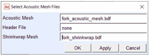
9. Select: This button opens an additional dialog box (see below) to select acoustic mesh files individually.
Dialog to select the acoustic mesh files individually:
10. Create: This button creates the acoustic mesh if the "Automatic mesh" or "Shrinkwrap provided" options are chosen for Mesh Type.
11. Show: This button displays the acoustic mesh in Adams View:
Visualized acoustic mesh:
12. Edit: This Button opens the shrinkwrap mesh in Actran VI. Please note that for mesh modifications, an Actran VI license is necessary, the "Actran Entry for Adams" license is not sufficient for this option.
13. Status: This button displays the current status of the meshes in the info window.
Note that an Actran Time Domain analysis cannot be submitted if no mesh is available for the analysis.
Results Content Tab
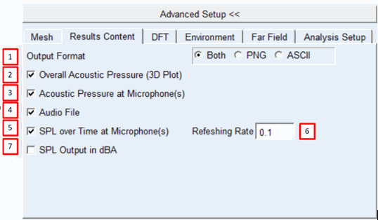
In the results content tab, the post-processing content is defined. The inputs are described below.
1. Output Format: Defines the output format of the results. Images, ascii-format and both can be chosen.
2. Overall Acoustic Pressure (3D Plots): Plots the time dependent results of each microphone in a waterfall diagram.
3. Acoustic Pressure at microphone(s): Creates the acoustic pressure results for each microphone defined in Microphone for Post on the Far Field tab.
4. Audio File: Creates a wave-file for each microphone defined in Microphone for Post on the Far Field tab.
5. SPL over time at microphone(s): Creates the Sound Pressure Level (SPL) per time period in a time dependent plot.
6. Refreshing Rate: The time period (in seconds) over which the Sound Pressure Level SPL is integrated.
7. SPL output in dBA: Applies the A-weighting function to acoustic results expressed in dB.
Discrete Fourier Transformation (DFT) Tab
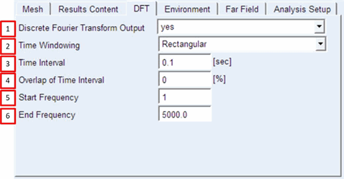
The Discrete Fourier Transformation (DFT) tab contains the properties for the transformation of time domain signals into frequency domain results. The inputs are described below. See the Discrete Fourier Transform (DFT) section of the Appendix for more details.
1. Discrete Fourier Transform Output: Activates the transformation of time results to frequency domain
2. Time Windowing: Defines the form of the window. While Rectangular window will apply a constant factor of 1 (thus no window) to the sampled time signal, other window types will apply factors from [0,1] to the sampled time signal. Options are Triangular, Hamming, Hanning, Blackman and Blackman Harris. For example, the Hanning windowing is defined by the formula with n the number or the
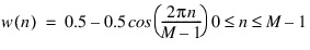
sample points, M the quantity of sample points in the window and w the window function
3. Time Interval: Defines the length of each time interval where the DFT is applied
4. Overlap of Time Interval: Defines the percentage of the overlap of the subsequent time interval.
5. Start Frequency: defines the first computed frequency in the DFT. Default value is defined by the period of the time interval.
6. End Frequency: defines the last frequency to be computed during the DFT. Note that the time step length influences the maximal frequency that can be computed, through the Nyquist criterion.
Environment Tab
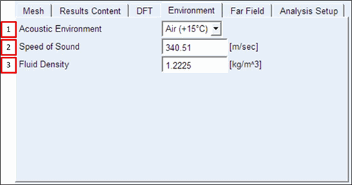
The Environment tab defines the properties of ambient fluid surrounding the structure:
1. Acoustic Environment: Allows to automatically define the properties of the Air at a given temperature. Following properties are influenced by the temperature defined.
2. Speed of Sound in m/s
3. Fluid Density in kg/m³
Far Field Tab
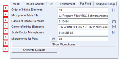
The Far Field Tab defines the position of the microphones and the properties of the infinite elements. The inputs are described below. See the Far Field section of the Appendix for more details.
1. Order of Infinite Elements: Defines the number of interpolation points for each infinite element, which is used to model non-reflecting boundary conditions and the acoustic radiation outside of the finite element mesh. Default value is 10.
2. Microphone Table File: Defines the position of the microphones; the default position is based on the ISO3744 and can be found in the installation folder "<top_dir>\acoustics\examples\ISO3744_meter.mic"
3. Radius of Infinite Elements: Defines the coordinate system of the infinite elements.
4. Center of Infinite Elements: Defines the location of the center of the infinite elements.
5. Scale Factor of Microphones: Scales the coordinates of the microphone positions.
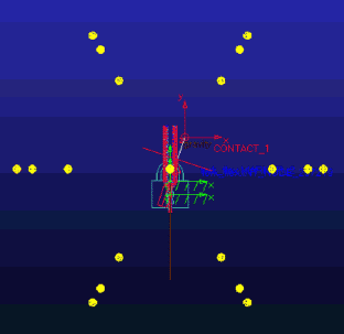
6. Microphone for Post: Select the microphones used for additional post-processing output; the button "All" will select all microphones
7. Show Microphones: This button is enabled after the acoustic mesh is generated and displays all the micro-phones available as yellow or red spheres (the red ones indicate microphones selected for extra post-processing results)
8. Overwrite defaults: Radius of Infinite Elements, Center of Infinite Elements and Scale Factor for Microphones all have automatic defaults. This "Overwrite defaults" button allows users to change those inputs. For instance, the user can change the distance of the microphones from structure by modifying the scaling factor for microphones.
Analysis Setup Tab
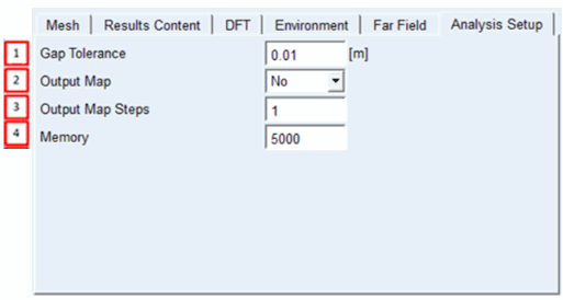
In the Analysis Setup tab, the following parameters are defined. See the Analysis set-up section of the Appendix for more details.
1. Gap Tolerance: Defines the tolerance parameter to couple the shrinkwrap with the structural acoustic surfaces. Default value is twice the distance specified in Mesh tab, which can be used in other cases as well.
If distance is 0.0, Gap Tolerance is set to 0.01 m.
2. Output Map: Allows user to create an acoustic 3D map in time domain.
Please note that:
■To open the map in Actran VI the license for Actran VI is needed, the "Actran Entry for Adams" license is not sufficient.
■Asking for maps may increase computational time significantly.
■Default value is 'No'.
3. Output Maps Steps: Specifies the time steps of the output map. Please note that an output map can demand a lot of hard drive space thus removing steps from the output could be important. Maps are output at each time step for value=1, every two steps for value=2 and so on.
4. Memory: Memory dedicated to the calculation. Quantity depends on the size of the acoustic mesh. Unit is MB.