FMI Interface: Virtual Test Drive
(Standard Interface) Simulate → FMI Interface → Export to VTD
Runs a Virtual Test Drive analysis.
For running an Adams model as a plant in VTD, the model should use the SDI Test Rig. Two interfaces in between Adams and VTD are available:
1. RDB interface, which uses a UDP connection over the internet
The Export to VTD dialog will become available after loading the Adams Controls plugin. For both interfaces the same FMU can be used.
Typically the inputs to the Adams model from VTD are:
■Steering wheel angle
■Throttle
■Brake
■Gear
■Road height and friction data
The outputs contain at least the part states of the vehicle chassis (9 states per part), all the wheels of the vehicle (7 states per wheel), the engine rpm and throttle. The user can select to visualize additional parts in VTD.
In case of the FMI interface one can add user specific input and output plant variables, this, however, should match with the FMI interface in VTD.
The user should take care that the Adams and VTD vehicle models match with respect to all vehicle dynamics properties.
By default, the Export to VTD dialog will generate an FMU, unless the 'interactive' simulation model is selected. In the 'interactive' mode a simulation will be started directly that will use the UDP interface. The simulation will also generate a message and results file for debugging purposes.
RDB interface
In this setting VTD and Adams simulate parallel in real-time mode and the data is transferred via a UDP connection. The Adams model needs to have the right hostname of the machine on which VTD is running.
VTD will run at Linux operating systems only, but Adams can run at any Adams supported platform as long as there is an internet connection to the VTD platform and the required ports are not blocked by a fire wall. The ports being used are 48190, 48191, 48270 and 48271.
Note that the data transfer via UDP can be effected by internet activity resulting in data loss or no-sync data exchange, therefore the FMI interface is preferred in most cases.
Before starting the Adams simulation via UDP, following environment variables need to be set:
MSC_ADAMS_VTD_INTERFACE="UDP"
MSC_ADAMS_VTD_HOSTNAME="name of the machine with VTD running"
FMI interface
Using the FMI interface guarantees a one to one data exchange in between VTD and Adams because a clear parent (VTD) - client (Adams) relation will be set up. In this setting real time applications or applications at lower speed can be run as well.
The interface allows to select additional parts for visualization and user specific variables (need to be supported by the VTD vehicle model).
For the option: | Do the following: |
|---|---|
Full-Vehicle Assembly | Select the Full-Vehicle Assembly you want to analyze. The menu lists all full-vehicle assemblies currently open in your session. |
Assembly Variant | Select the assembly variant you want to analyze. The menu lists all full-vehicle assembly variants of the chosen assembly. |
 | Switches to the selected variant and adds the required testrig as needed. |
Output Prefix | Enter a string that specifies the Analysis Output Name. The string can contain only alphanumeric characters and underscores (_). Adams Car appends the _vtd_adams to form the complete analysis name. For example, if you enter test_45 as the output prefix, the analysis name becomes test_45_vtd_adams. |
Output Step Size | When the Simulation Mode is set to Interactive, this value specifies the step size for the simulation and will also determine the basic interface frequency with VTD. When the Simulation Mode is set to files_only, this value does not hold any significance. The FMI parent (in this case VTD) steps the simulation using a step size specified within VTD. |
Advanced options | Allows to be more specific in the in- and output signals of the FMU and the simulation model. |
Additional Input Signal(s) | In addition to the standard input signals provided by VTD (Steering, Throttle, Brake and Gear) other signals can be selected. Note, this needs to be supported by the VTD vehicle model. (FMI interface only) |
Additional Output Signal(s) | In addition to the standard output signals provided by Adams (vehicle body states and wheel states) other signals can be selected. Note, this needs to be supported by the VTD vehicle model. (FMI interface only) |
Parts Accessible within VTD | In addition to the chassis part (always selected by default) other parts in the Adams model can be selected to be visualized in VTD. |
Initial Velocity | The velocity at which the vehicle should start driving. |
Gear Position | Specify the initial gear position for the analysis. This gear setting is used by the powertrain for the statics and the start of the dynamics. |
Simulation Mode | Select interactive or files_only. In ‘files_only’ mode, an FMU will be generated. The FMU can be used for the RDB and FMI interface. This can be imported into VTD. With 'Interactive' mode, a simulation will be started with the current model using the RDB interface. The output will be send to the specified hostname. You need to start the VTD before the simulation is submitted. In the 'Interactive' model, the message file and results file will be generated for debugging purposes. |
Quasi-Static Straight-Line Setup | Select to perform a quasi-static prephase analysis before running the transient analysis on your full-vehicle assemblies. Selecting this option causes Adams Car to perform a STRAIGHT (sometimes called ClearVision adjustment) analysis. If you do not select this option, Adams Car performs a SETTLE analysis. For more information about the different quasi-static setup method keywords (such as SETTLE and STRAIGHT), see Structure of Event Files. Note: You cannot select the Quasi-Static Setup option if: You do not have a powertrain subsystem in your vehicle assembly, because it is not possible to set the initial condition for the longitudinal or the lateral dynamics (throttle position). |
End Time1 | Specifies the time, in seconds, at which the analysis ends (interactive simulation mode only). |
Hostname1 | Specifies the hostname of the machine with VTD running (interactive simulation mode only). |
Create Event Log File | Select if you want Adams Car to write information about the assembled model and analysis to an Analysis Log File. |
 | Checking this checkbox will allow user to encrypt the Adams Solver dataset file (.adm) exported within the fmu. Such encrypted Adams Solver dataset files will have the extension .adme. If any of the model parameters are exposed then this feature will be disabled. This checkbox is available only for FMU v1.0 and FMU v2.0. Solver will not allow a LIST argument on an object command in encrypted models. |
 | Clicking on this button opens up a dialog where model parameters can be selected for export. Parameter variables, hard points, mass properties, UDE design variables and property files are supported. This button is also disabled if Encrypt Model option is chosen. |
 | Select to display a dialog box where you can add multi-line comments to any entity, to describe its purpose and function. Adams Car displays different comments dialog boxes, depending on the entity type for which you want to record comments: ■If recording comments for modeling entities in Standard Interface, Adams Car displays the Entity Comments dialog box. ■If recording comments for any other entity type, Adams Car displays the Modify Comment dialog box. Learn about Recording Comments. |
 | Select to display an Alignment dialog box where you can set toe, camber and caster alignment values. |
1applicable for 'interactive' simulation model only.
Data exchange of the VTD-Adams interface
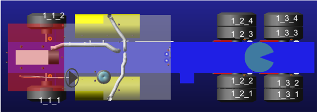
The data sent from the Adams model to VTD contains the states of the parts and wheels that need visualization within VTD. For each part these exist of the translational and rotations displacements (6) and translational velocities (3). For each wheel following states are forwarded:
■rotation angle
■longitudinal slip
■compression of the wheel with respect to the chassis part
■steering angle
■wheel radius
■x and y position
The wheel id's of these states are defined with 3 digits:
■First digit for the part id on which the wheel is mounted
■Second digit determines the axle id, counting from front to rear
■Third digit for the wheel on the axle, counting from left to right
When creating the FMU or submitting an interactive simulation, the variables for these input and output signal are created on the fly. You do not need to take any concern for these signals, unless you define some user specific input or output signals.
The modelDescription.xml and modelInfo.xml in the FMU will describe the signals that are being used as input and output.
Remote Access Procedure to Linux Machine Running VTD
If you have to access Linux machine remotely for VTD interactive simulation, you will need to install NoMachine freeware. Here are the steps to follow:
1. Download NoMachine For Windows and NoMachine For Linux from https://www.nomachine.com/download
2. Install on Windows and Linux machine. (For Linux machine install under /usr/ directory.)
3. On Windows machine open NoMachine from start menu. Enter required Linux machine details such as machine name/user/password and then connect to Linux machine physically like windows remote desktop.