Using the Driving Machine
You use the Driving Machine to perform full-vehicle analyses. The Driving Machine drives your virtual vehicle according to your instructions much like a test driver would drive an actual vehicle. The Driving Machine steers the vehicle, applies the throttle and brake, and shifts gears (using the clutch). You can instruct the Driving Machine to switch between open- and closed-loop (Machine Control and SmartDriver) control during a simulation.
Using open-loop control, the Driving Machine can, for example, input a swept-sinusoid to the steering or play back recorded steering, throttle, brake, gear, and clutch signals as input to your virtual vehicle. This lets you use data acquired in real tests as input to your virtual vehicle.
Using Machine Control, which replaced DriverLite, the Driving Machine can, for example, steer a vehicle around a skid-pad, while gradually increasing speed. You use Machine Control to have the vehicle follow a path and maintain a specified longitudinal speed or acceleration. Inputs to Machine Control are the target path the vehicle should follow and/or a target speed or longitudinal acceleration vs time or distance.
Using Adams SmartDriver, you can determine the maximum performance of a vehicle as it follows a specified path. Adams SmartDriver is an extra-cost, add-on product that lets you specify a desired performance criterion (for example, 100%, 80%, 50% of vehicle limits) for the vehicle as it follows the defined path. Adams SmartDriver then creates a target longitudinal speed along the path that meets the desired performance criterion.
Adams Car stores your instructions to the Driving Machine in an XML event file. You can use the Event Builder (or any text editor) to create or modify an event file.
Note: | We changed the Driving Machine architecture to support XML files as the default, while maintaining support for legacy dcf files. If you specify a dcf file, Driving Machine automatically converts it to an XML file in the working directory so you can use the Event Builder to review and modify the event. |
Driving Machine reads recorded open-loop signals and vehicle path and velocity data from text files named driver control data files (.dcd).
To help you calculate the control signals, Adams Solver passes vehicle information such as position, velocity, and acceleration, to the Driving Machine. The Driving Machine provides a means for defining and passing sets of command signals, feedback signals, and parameters for each of the five control signals (steering, throttle, brake, gear, and clutch).
The following figure shows how the Driving Machine works in a virtual prototyping model.
Learn more about the Driving Machine:
What You Can Do with the Driving Machine
Using the Driving Machine, you can:
■Input the vehicle path {x, y} and speed, and use closed-loop, Machine Control, to steer a vehicle along a path or follow a desired velocity or both (the table, Closed-Loop Data in .dcd Files, lists all potential inputs).
■Input a variety of open-loop functions, such as swept-sine and impulse, to the steering, throttle, or brake.
■Input recorded steering, throttle, brake, gear, and clutch signal to your model.
■Stop a simulation, switch controllers, and change output-step size based on reaching a target lateral acceleration, longitudinal velocity, or distance traveled.
■With the optional Adams SmartDriver closed-loop control, you can specify a desired vehicle performance level, such as 100% or 50%, and input a path and speed as you would for Machine Control.
How You Benefit from Using the Driving Machine
When working with the Driving Machine, you have the following benefits:
■You save the time you previously needed to set proper gains for closed-loop controllers. The Driving Machine incorporates proprietary control algorithms from MSC Software.
■You shorten simulation times by ending simulations based on targets for lateral acceleration, longitudinal velocity, and distance traveled.
■You gain flexibility in how you input vehicle paths and desired velocity profiles, choosing from recorded data stored in external files or parametrically generated paths and profiles based on a few simple inputs.
Steps in Using the Driving Machine
Follow these steps to use the Driving Machine:
1. Assemble a full-vehicle model with the .__MDI_SDI_TESTRIG test rig or open an existing full-vehicle assembly.
2. Do either of the following:
■Use a predefined analysis (from the Simulate menu, point to Full-Vehicle Analysis, and then point and select the predefined analysis you want).
■Create your own event file to perform your specific set of simulations (from the Simulate menu, point to Full-Vehicle Analysis, and then select Event Builder).
Tips on Creating Paths for Driving Machine
Applies to Machine Control and SmartDriver
The following are tips for creating paths for the Driving Machine.
Remove Excess Noise
The TARGET path used by the steering controller is defined by fitting the path data referenced in the event file. The TARGET path will pass through every point in the path data.Therefore, any irregularities included in the path description, such as the noise coming from telemetry data, are seen by the steering controller and can produce a quickly changing steering input. To minimize noise in the steering torque you may want to preprocess the path data to remove noise and/or add corner cutting, and then store the resulting path in a .dcd file.
Path Point Spacing
The suggestion previously described here regarding path spacing no longer applies (as of version 2011), except if/when the environment variable MSC_SD_USE_SPLINE is set (to zero) to revert to pre-2011 behavior.
Path transformation
Depending on the steering control input that is used, paths may be transformed (translated and/or rotated) to align the beginning of the path with the initial position/orientation of the vehicle. Paths obtained by extracting road centerlines from road data are not transformed by default to prevent misalignment of the path used by the driving machine and the road used by the tires and road graphics.
Following table shows the transformations applied to the path for the different steering control inputs:
Steer Control Input | Path Translational Transformation | Path Rotational Transformation |
|---|---|---|
Driver Control Data File (.dcd) | X | X |
Driver Road Data File (.drd) | X | |
Road Data File (.rdf, .xml, .crg, .rgr) | ||
Event (.xml) | X | X |
To override the default behavior, set environment variable MSC_SD_ALLOW_PATH_TRANSFORM to:
0: forces no transformation
1: forces a transformation to be performed
When paths are transformed, the driving machine will traverse the path in the direction which most closely matches the initial vehicle yaw. To override the default behavior, set environment variable MSC_SD_S_ASCENDING to traverse the path in the direction of ascending s (postive value), descending s (negative value) or whichever direction most closely matches initial vehicle yaw (0), default=0.
Examining path fit
Result sets useful for examining the quality of fitting the path data are automatically created for interactive simulations by importing numerical results from {analysis_name}_xxx.pth files, created when the spline is fit during the simulation, where xxx is:
■raw - original discrete path points
■bsp - bspline fit of raw points
■tra - transformed bspline fit of raw points
The {analysis_name}_xxx.pth files are deleted once the automatically created result sets are created. You can use Adams Postprocessor e.g. to plot result set path_1_original Y:X and path_3_bspline Y:X to see how well the bspline fits the original path data.
For external simulations, the {analysis_name}_xxx.pth files are not deleted and can be manually imported in Adams Postprocessor.
You can set MSC_SD_PATH_DUMP to 0 to prevent production of the .pth files.
The default spacing of points in the .pth files is 0.5m. MSC_SD_PATH_DUMP_INTERVAL can be set (positive real values) to increase or decrease the spacing of points in the _bsp and _tra .pth files (to detect local spline “buckling” for example.)
Data Flow in Driving Machine
When you submit a simulation using the Driving Machine, Adams Car generates an Adams Solver command file (.acf), an Adams Solver dataset file (.adm), and an XML event file. The .acf file instructs Adams Car Solver to read the dataset file and event file (using abgVDM::EventInit CONSUB). It also instructs Adams Car Solver to perform maneuvers described in the event file (using abgVDM::EventRunAll CONSUB). Adams Car Solver then provides the standard output files: .msg, .res, .gra, and .out.
The event file (.xml) describes the maneuver you want to perform as a list of mini-maneuvers. The event file can reference one or more driver control data (.dcd) files. Driver control data files contain either closed-loop or open-loop data. An example of closed-loop data is vehicle path and speed (the table, Closed-Loop Data in .dcd Files, lists all potential inputs). Open-loop data are steering, throttle, brake, gear, and/or clutch signals versus time.
The following figure summarizes the data flow specific to the Driving Machine.
Template Updates
The 2005 Driving Machine employs vehicle controllers developed by MSC Software, commonly known as Machine Control, which replaces DriverLite functionality, and Adams SmartDriver. To better control speed and path, the 2005 Driving Machine needs additional information about the vehicle. In particular, the speed controller uses a feed-forward function to ensure quick and accurate response. However, this requires information about the available engine brake torque, engine drive torque, brake torque, and aerodynamic drag. You supply this information by creating new output communicators in your templates. In addition, you must also enter vehicle parameter data, such as overall steering ratio that is stored in the assembly file.
For more information, see Working with Templates->Template Updates.
Limitations of the Driving Machine
The Driving Machine has the following limitations:
■It can only accurately steer a vehicle when positive steer inputs steer the vehicle to the left.
■It can only drive the vehicle within the vehicle's limits of lateral and longitudinal acceleration, and longitudinal velocity.
Working with Driver Control Data Files (.dcd)
You use driver control data (.dcd) files to specify:
■The closed-loop data, such as path and speed you want a vehicle to follow.
■The open-loop data, which is the steering, throttle, brake, gear, and clutch signals versus time you want to input to a vehicle.
To use a .dcd file, you must reference it from an event file (.xml).
Driver control data files contain data for use by the Driving Machine. To instruct the Driving Machine to use the data from a .dcd file, you must reference the file in an event file (.xml). An excerpt from a .xml showing a reference to a .dcd file looks like the following:
(STEERING)
METHOD = 'OPEN'
CONTROL_TYPE = 'DATA_DRIVEN'
FILE_NAME = 'my_data.dcd'
Driver control data files hold two types of data:
■Open-loop data - Data that is played back as input to the vehicle without concern for how fast or where the vehicle goes. Such data includes: steering-wheel angle, throttle, brake, gear, and clutch signals. Examples of open-loop data include steering-wheel angle versus time, and throttle position versus time.
■Closed-loop data - Data that specifies exactly where and how fast the vehicle should go. An example of closed-loop data is vehicle x and y position versus time. You can specify closed-loop data in several forms. For example, curvature and velocity versus distance traveled, or lateral acceleration and longitudinal acceleration versus time. You specify the type of data using the SPEED_CONTROL and STEERING_CONTROL arguments in the .dcd file.
Learn about .dcd files:
Structure of Event Files
Event files contain the following type of information:
■Name of Event File
■Speed
■Gear Number
■Static Setup
■Gear Shifting Parameters
■Mini-Maneuvers for the Experiment
Name of Event File
When you assign a name to the event file, Adams Car automatically generates a file with extension .xml in the working directory and updates the Event File text box with the file name you entered.
Speed
Represents the initial vehicle speed for the maneuver.
Gear Number
Represents the initial gear position for the maneuver.
Static Setup
You can specify static-setup analyses that remove start-up transients that can eliminate mini-maneuvers that you might normally use to set up a vehicle for cornering maneuvers. For example, in the past, to perform a brake-in-turn analysis you might have run a transient mini-maneuver to have the vehicle turn-in and reach static-setup on given turn, at a given speed/lateral acceleration, before starting to brake the vehicle. This approach is equivalent to a test driver on a proving ground, driving at a steady speed and in a steady-state condition (vehicle has no transients) before starting a dynamic maneuver (braking, acceleration, steering, and so on). Now you can perform a much faster (less CPU time) static-setup analysis.
You can set static setup to any of the arguments described next.
Arguments
none | Adams Car does not perform a static equilibrium analysis. Rather, it locks the wheel rotations and then performs an acceleration initial-conditions analysis, which initializes Adams Tire. Adams Car then deactivates the wheel lock joint primitives before executing the first mini-maneuver. |
normal | Locks the wheel rotations using joint primitives, but leaves the body free to move in the fore-aft, lateral, and yaw directions. Soft springs (1 N/m and 10 N m/radian), introduced by Adams Tire just for static equilibrium, acting in all directions between each wheel center and ground limit, but do not prevent, body yaw, fore-aft, and lateral displacements. Then, before executing the first mini-maneuver, Adams Car deactivates the joint primitives to unlock the wheel rotations, and Adams Tire removes the soft springs. The transitional and torsional stiffnesses supplied by the tire act in all directions (x,y,z). Without these stiffnesses, the vehicle would have a neutral equilibrium position in the x-y plane of the road. |
settle | Locks the body's fore-aft, lateral, and yaw displacement using joint primitives and performs a static equilibrium to settle the vehicle on the road. Then, before executing the first mini-maneuver, Adams Car deactivates the joint primitives. For example selecting settle and specifying an initial velocity of 27777.78 mm/s is equivalent to driving a stake vertically through the vehicle body and constraining the body to move vertically about the stake. It allows the vehicle to roll (cornering) and pitch (braking), but does not allow rotation about the axis of the stake (Yaw). When the vehicle is released from this condition, it should be relatively well balanced to remove initial transient effects. An imbalance in the tire forces could, however, cause a slight steering effect. If you want to remove this effect, we recommend that you use straight. |
skidpad | Locks the body's fore-aft and lateral position using a joint primitive. Adams Car adjusts the steering and throttle so the vehicle's yaw rate, lateral acceleration, and speed match those prescribed by the initial radius, initial turn direction, and the initial lateral acceleration or initial speed. You must specify the initial radius and turn direction. Also, you must supply either the initial lateral acceleration or the initial speed. For example, selecting skidpad and specifying an initial radius, turn direction, and initial speed effectively performs a settle static setup followed by a straight static setup. Then, Adams Car adjusts the steering and throttle so that the vehicle's yaw rate, lateral acceleration, and speed match those prescribed in the event file. By carefully observing the .msg file Adams Solver produces, you can see the model manipulation occur. |
straight | Locks the body's fore-aft and lateral position using a joint primitive. Adams Car adjusts the steering (so that the vehicle's yaw rate and lateral acceleration are zero) and the throttle and/or brake (to balance any aerodynamic drag and scrub that the tires produce and to match the specified initial longitudinal acceleration). Then, before executing the first mini-maneuver, Adams Car deactivates the joint primitives. The maneuver has two separate static analyses: the first uses the settle method, the second uses a force balance on the vehicle body to ensure that the net lateral force is negative (the vehicle is traveling in a straight line) and that longitudinal forces are zero. The values for steering-wheel angle, throttle position, and so on, are used as initial conditions for the subsequent dynamic analysis. |
Gear-Shifting Parameters
Define the gear-shifting properties and the shape of the upshift and downshift curves for throttle and clutch signals.
Arguments
Throttle Fall Time | Delta time of the step function for the descending curve of the throttle signal (> 0.0) |
Clutch Fall Time | Delta time of the step function for the descending curve of the clutch signal (> 0.0) |
Throttle Raise Time | Delta time of the step function for the ascending curve of the throttle signal (> 0.0) |
Clutch Raise Time | Delta time of the step function for the ascending curve of the clutch signal (> 0.0) |
Shift Time | Duration of the gear shifting event (> 0.0) |
RPM Control | Enables an algorithm for RPM limiting during gear shifting |
Mini-Maneuvers
The Driving Machine runs each mini-maneuver in the order listed, until the list is ended or a mini-maneuver is terminated.
For each mini maneuver, you must specify a name for the mini-maneuver, the control signals (steering, throttle, braking, gear, and clutch), as well as the condition for ending the mini maneuver. Learn more about Creating Mini-Maneuvers.
Structure of .dcd Files
Driver control data (.dcd) files use a TeimOrbit File Format similar to other Adams Car property files. Driver control data files must contain these data blocks:
■MDI_HEADER block - Identifies the file as a .dcd file and provides version information.
■UNITS block - Identifies the units of the data contained in the .dcd file.
The driver control data file must also contain at least one of two data blocks:
■OPEN_LOOP block - Specifies the steering, throttle, brake, gear, and clutch inputs to the vehicle.
■CLOSED_LOOP block - Specifies the path or the speed of the vehicle, or both.
Note: | Driver control data files can contain both open-loop and closed-loop blocks. |
Specifying Closed-Loop Data
When reading the following specification you should observe the following rules:
■[ ] = Data block
■( ) = Sub-block
■{ } = Data header
■|| = Options, and means OR
■&& = And
The nomenclature is:
■lon_vel = Vehicle longitudinal velocity
■lon_acc = Vehicle longitudinal acceleration
■lat_acc = Vehicle lateral acceleration
■distance = Arc-length or distance traveled along the path
■curvature, k=1/radius
■x = X position of vehicle relative to ISO-Earth Axis System
■y = Y position of vehicle relative to ISO-Earth Axis System
■{ } = Set of inputs
The following table summarizes the closed-loop data that a .dcd file can contain:
■The columns represent speed-control options from the driver parameters array.
■The rows represent the steering control options from the driver parameters array.
■The intersections give the data contained in the .dcd file and, therefore, the data input to the funnel to produce {x, y, lon_vel} as needed by Driving Machine.
Closed-Loop Data in .dcd Files
SPEED_CONTROL STEERING_CONTROL | none | lon_vel | lon_acc | lat_acc | path |
|---|---|---|---|---|---|
none | NOT VALID | {(distance or time), lon_vel} | {(distance or time), lon_acc} | NOT VALID | NOT VALID |
curvature | {distance, curvature} | {(distance or time), curvature, lon_vel} | {(distance or time), curvature, lon_acc} | {(distance or time), curvature, lat_acc} | NOT VALID |
path | {x, y} | {x, y, lon_vel} | {x, y, lon_acc} | {x, y, lat_acc} | {x, y, time} |
lat_acc | NOT VALID | {distance or time, lat_acc, lon_vel} | {distance or time, lat_acc, lon_acc} | NOT VALID | NOT VALID |
Creating .dcd Files
You can use the sample .dcd files that we provide or you can create your own .dcd files.
To create .dcd files:
1. You can use one of three methods to create .dcd files:
■Run a physical or virtual test and record the data that you obtain from the five actuator application areas.
■In a text editor, modify the sample .dcd files that we provide for you.
■Create a .dcd file using a text editor and following the specifications and format shown in Specifying Closed-Loop Data and Example .dcd File Architecture.
2. Save the file and reference it when running File-Driven Analyses.
Example .dcd File
The following shows the architecture of a .dcd file and all the options you can set for a .dcd file. It contains options, logic, and general rules that you must follow when creating a .dcd file.
[MDI_HEADER]
FILE_NAME = filename.dcd
FILE_TYPE = 'dcd'
FILE_VERSION = 1.0 FILE_FORMAT = 'ASCII'
(COMMENTS)
{comment_string}
'Any comment'
[UNITS]
LENGTH = 'meter' || 'millimeter' || 'centimeter' || 'kilometer' || etc.
FORCE = 'newton' || 'kilogram_force' || etc.
ANGLE = 'deg' MASS = 'kg'
TIME = 'sec'
[CLOSED_LOOP]
comment = string
steering_control = 'none' || 'curvature' || 'path' || 'lat_acc'
speed_control = 'none' || 'lon_vel' || 'lon_acc' || 'lat_acc' || 'path'
ordinal = 'distance' || 'time'
lon_vel_max = float
lon_vel_min = float
lon_acc_max = float
lon_acc_min = float
lat_acc_max = float
lat_acc_min = float
(DATA)
$ steering, speed
$ 1 Case{none, none} -- null case, no data required!!
$ 2 Case{none, lon_vel}
$ 3 Case{none, lon_acc}
$ 4 Case{none, lat_acc} -- NOT VALID
$ 5 Case{none, path} -- NOT VALID
{ ( distance || time ) && ( lon_vel || lon_acc ) }
$ 6 Case{curvature, none} -- Must have distance with curvature
{ distance && curvature }
$ 7 Case{curvature, lon_vel}
$ 8 Case{curvature, lon_acc}
$ 9 Case{curvature, lat_acc}
$10 Case{curvature, path} -- NOT VALID
{ ( distance || time ) && curvature && ( lon_vel || lon_acc || lat_acc )}
$11 Case{path, none}
$12 Case{path, lon_vel}
$13 Case{path, lon_acc}
$14 Case{path, lat_acc}
{ x && y && ( lon_vel || lon_acc || lat_acc ) }
$15 Case{path, path}
{ x && y && time }
$16 Case{lat_acc, none} -- NOT VALID
$17 Case{lat_acc, lon_vel}
$18 Case{lat_acc, lon_acc}
$19 Case{lat_acc, lat_acc} -- NOT VALID
$20 Case{lat_acc, path} -- NOT VALID
{ ( distance || time ) && lat_acc && ( lon_vel || lat_acc ) }
[OPEN_LOOP]
ordinal = 'time' || 'distance'
{distance || time steering throttle brake gear clutch}*
0.0 0.0 0.0 0.0 2 0.0
0.1 0.0 0.0 0.0 2 0.0
*You can select distance or time and any combination of steering, throttle, brake, gear, and clutch.
Example corresponding to $ 2 Case{none,lon_vel}:
.....
[CLOSED_LOOP]
STEERING_CONTROL = 'NONE'
SPEED_CONTROL = 'LON_VEL'
ORDINAL = 'TIME'
(DATA)
{ TIME, LON_VEL }
0.0 27.777
0.1 27.777
0.2 27.776
0.3 27.775
0.4 27.774
0.5 27.773
.....
Example corresponding to $ 7 Case{curvature,lon_vel}:
.....
[CLOSED_LOOP]
STEERING_CONTROL = 'CURVATURE'
SPEED_CONTROL = 'LON_VEL'
ORDINAL = 'DISTANCE'
(DATA)
{ DISTANCE, CURVATURE, LON_VEL }
0.0 0.000 27.777
1.0 0.002 27.777
2.0 0.004 27.777
3.0 0.006 27.776
4.0 0.008 27.775
5.0 0.010 27.774
6.0 0.010 27.773
7.0 0.010 27.774
8.0 0.010 27.774
9.0 0.010 27.774
10.0 0.010 27.774
11.0 0.010 27.774
12.0 0.010 27.774
13.0 0.010 27.774
Machine Control Basics
Machine Control is a vehicle controller that you can use to simulate the control actions of a driver. You simulate the actions of a driver by operating the steering, pedals, and gears of a simulated vehicle.
Machine Control determines control actions such that a simulated vehicle can follow meaningful combinations of a specified path along a 2D or 3D road, a specified curvature, a specified lateral acceleration, a specified longitudinal velocity and a specified longitudinal acceleration. Machine Control's control action combines a reference trajectory planner and a model-predictive controller (MPC), sometimes known as a feed-forward plus feedback controller.
At the trajectory planning stage, your targets for the vehicle and driver behavior and some basic parameters describing the characteristics of the simulated vehicle are taken into account, and a realistic trajectory that most closely satisfies your targets is identified (for example, path, speed, and acceleration).
Machine Control uses simple mathematical models of vehicle dynamics, such as a bicycle model, a particle model, and a kinematic drivetrain model, to estimate the necessary control actions, such as the steering angle and throttle position. Machine Control applies these estimated controls as inputs to the simulated vehicle in a feed-forward manner, such that approximately correct control actions are applied without delay.
Differences between the behavior of the simulated vehicle and the expected behavior (that is, the behavior of the idealized models employed by the controller) are corrected continuously using feedback controllers, which adjust the control actions to minimize the error between the reference trajectory and the actual vehicle behavior.
Learn more about Machine Control:
Feed-Forward Control
Feed-Forward Lateral Control
Global axes, x-y, local axes, X-Y,
vehicle path and global yaw angle, 
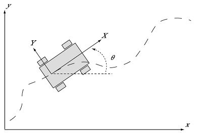
The projection of the vehicle path onto the ground plane is related to the velocities and global heading
as:
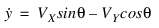
where:
(X,Y) | Global position of the vehicle |
(VX, VY) | Velocities of the vehicle relative to vehicle-fixed axes |
 | Global heading of the vehicle |
The feed-forward component of the lateral control action is computed by assuming that your simulated vehicle responds as a bicycle model. The simplicity of the bicycle model allows the analytical identification of the relationship between the geometry of the path and the necessary control action (steering angle), and vice-versa.
In a bicycle model, the lateral forces from both tires on an axle are assumed to act in the same direction, and the left and right steer angles are assumed to be the same. In other words, Ackerman steering geometry is not considered. With these assumptions, the tires may be lumped together into a single tire representation, and the model is guided by a single steer angle.
This simplified model is used to identify the necessary steer angle required for the vehicle to follow the specified target.
Simplification of a vehicle to the bicycle model
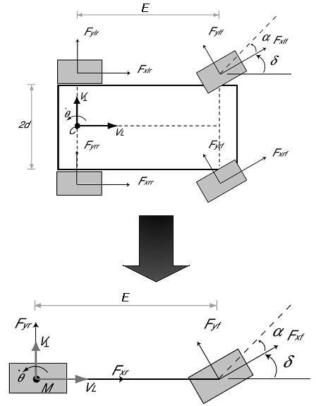
The form of the bicycle model employed by Machine Control assumes pure rolling of the front and rear tires with no kinematic or compliance-steer effects, and therefore, no lateral velocity at the rear axle. Note that this does not imply zero sideslip at the center of mass.
If the origin of the vehicle-fixed local axis system shown above is selected to be the center of the rear axle (not the center of mass), then the lateral velocity VY is now always assumed to be zero, and the assumed path of the vehicle simplifies to:
where:
 | Rate of change of the direction of the path at the rear axle (note that this is not equal to the yaw rate of the vehicle). |
In this case, the center of the turn always lies on a line through the rear axle. The steer angle required to yield a certain path curvature is then always equal to the Ackerman angle, and is independent of the vehicle speed VX:
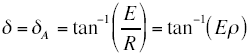
where:
E | Wheelbase of the vehicle |
R | Radius of the turn at the rear axle |
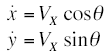
 | Curvature of the path of the rear axle  |
and, therefore, this single steer angle input to the bicycle model controls the radius of turn and the curvature of the path. A simple inversion of this equation enables an estimate of the necessary steer angle to be calculated and applied to the simulated vehicle in a feed-forward sense.
Feed-Forward Longitudinal Control
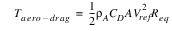
To control either the velocity or acceleration of the simulated vehicle such that they match the reference, a particle model, a simple aerodynamic drag model, and a kinematic drivetrain model are used to predict the relationship between the wheel torque and the acceleration response of the vehicle.
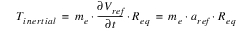
The force or torque required to accelerate or decelerate the vehicle is expressed as a wheel torque, that the engine and brakes must apply to one or more wheels. The magnitude of the required torque is computed from the vehicle drag, inertia and (optionally) tire rolling resistance.
Tw = Tinertial + Taero-drag+ Trolling-resistance
where:
where:
Tw | Total net wheel torque required to follow the reference |
Tinertial | Component that is required to accelerate the vehicle inertia |
Taero-drag | Required to overcome aerodynamic resistance |
me | Mass of the vehicle |
aref | Target (reference) vehicle acceleration |
Vref | Target (reference) vehicle speed |
Req | Average rolling radius of the wheels |
 | Density of air |
CD | Nominal drag coefficient of the vehicle |
A | Frontal area of the vehicle |
The default is not to include tire rolling resistance in Tw because this can cause poor performance, if the road is not smooth. Including tire rolling resistance can be beneficial for some simulations, if the vehicle is heavy (or if tire rolling resistance accounts for a significant fraction of the overall longitudinal force for other reasons.).
Gear Shifting
Gear shifts are triggered on the basis of engine speed thresholds, and the gear is incremented according to the following strategy:
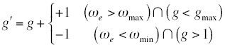
where:
g | Current gear selection |
g' | Revised gear selection |
w min | Minimum engine speed allowed before a downshift is triggered |
w max | Maximum engine speed allowed before an up-shift is triggered |
g min | Highest available gear, or the number of available gears |
Note: | Driving Machine will not shift into neutral. |
Trajectory Planning
Connecting Contour
For the lateral control of the vehicle with a target path, a simple model of the vehicle (a bicycle model) is used to compute the control action that should cause the vehicle to follow the intended path. The simulated vehicle, however, may not exactly follow the target path because of differences between the simplified model and the simulated vehicle (see Note), or external factors (road roughness and aerodynamic disturbances).
Therefore, the potential for offset between the instantaneous vehicle location and heading, and the location and heading of the path must be considered. In considering the location and heading of the path, Machine Control builds a connecting contour between the current vehicle position (wherever it may be) and some point on the target path, along which the vehicle will be steered to later bring it back to the target path:
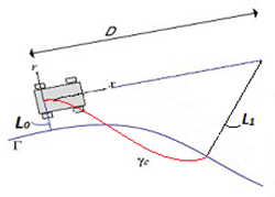
Connecting contour
where:
■D - preview distance = max(minimum, preview time * speed) - distance ahead from the current vehicle (gyro pt) position to locate preview point.
■L0 - path_distance - distance from current vehicle (gyro pt) position to the nearest point on the path, projected on the road surface.
■L1 - preview_point_distance - distance from preview point to the nearest point on the path, projected on the road surface.
The function that describes the connecting contour is parameterized such that one end of the connecting contour matches the position and direction of the vehicle (at the vehicle rear axle) and the other end of the connecting contour matches the path (at the preview distance, where the contour connects with the target path), as shown in the above figure.
The most potent (effective) adjustment to the connecting contour is the preview distance, which is typically controlled by changing the preview time. It is also possible (but less potent) to use alternate connecting contour shapes. The default connecting contour is a cubic with tangents matching the vehicle heading at both the "near" and "far" ends. Two alternate connecting contours are available: one is a cubic matching the vehicle heading at the "near" end and the path tangent at the "far" end; the other is a circular arc matching the vehicle heading at the "near" end and touching the target path at the far end. For some paths, notably skidpads, the alternate cubic and the circular options are superior to the default (which is best in the widest variety of situations.) Finally, and least potent in general but sometimes useful in marginal situations, it is possible to use the heading of the vehicle velocity rather than the vehicle heading (thus incorporating the body side slip angle) for the tangent at the "near" end of all three connecting contour types (and of the "far" end of the default cubic type) by setting MSC_SD_CONN_CONTOUR_BETA_CORRECTION to 1.
The connecting contour then becomes the reference trajectory (path) for the lateral control of the vehicle, and the vehicle is steered by both feed-forward and feedback controllers, such that it should follow this connecting contour. The connecting contour is updated each time the Machine Control controller is called.
Note: | The ._MDI_SDI_TESTRIG test rig creates a "gyro point" used as the origin for the connecting contour and determines the vehicle wheelbase used for the bicycle model based on the locations of the front and rear wheel centers as defined by the ci(l/r)_wheel_center(front/rear) communicators. For 2 axle vehicles, even those that do not steer at the front axle, the bicycle model provides an adequate feed-forward estimate when the path curvature is significantly bigger than the vehicle wheelbase. For vehicles with more than 2 axles, decide which axles to identify as "front" and "rear" so that the wheelbase and gyro point location based on those wheel center locations will provide a reasonable feed-forward estimate of the ratio of steer angle to path curvature and a reasonable origin for the connecting contour. |
Longitudinal Trajectory Planning
The longitudinal trajectory planning essentially consists of constructing either a target velocity against distance traveled along the track centerline, or a target acceleration against distance traveled, according to your description of the target (for example, acceleration against distance traveled, velocity against time).
Feedback Control
Yaw Rate Feedback
The yaw rate feedback component of the controller corrects for the difference between the yaw rate response of the simulated vehicle and that of the bicycle model. Errors between the yaw rate reference and the yaw rate of the simulated vehicle are quickly corrected, such that the simulated vehicle follows the intended trajectory as closely as possible, even if the feed-forward control identified from the bicycle model is significantly in error.
The yaw rate error is determined by considering the curvature that would result if the current yaw rate were a steady-state value, and is corrected using a feedback controller, whose output is also fed into the steering angle.
Yaw rate feedback can be used when following a specified path or specified curvature.
Lateral Displacement Feedback (Path Distance Compensation)
The connecting contour approach does not include any term to correct for steady-state lateral displacement error. This is preferred in most situations, because the resulting control actions tend to be more realistic and robustly stable. Once the vehicle is close to the target path, an additional controller acting on the distance L0 (path_distance) adjusts the lateral displacement of the vehicle:
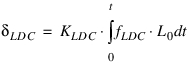
where fLDC is a flag indicating whether the lateral displacement controller is activated, that is whether the lateral displacement error Lo is small:

Note that in the above,
■Positive Lo indicates a vehicle to the left of the target path, requiring a positive steering correction.
■KLDC defaults to 1.0 and can be modified by setting MSC_SD_PDC_I_GAIN to the desired value.
■aLDC defaults to 1.0 and can be modified by setting MSC_SD_PDC_ROLL_OFF_RATIO to a value greater than or equal to 1.0
■L0crit defaults to 0.1m and can be modified by setting pathDistanceCompensationTolerance in the event file or in the Trajectory Planning tab of the Event Builder.
Longitudinal Velocity Feedback
Errors in longitudinal velocity are compensated using a PID controller:
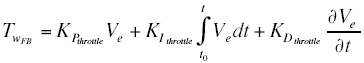
where the velocity error is:
Ve = Vref(s) - Vactual
where:
s | Distance along the reference path |
Vref(s) | Reference velocity |
Vactual = Vx | Longitudinal component of the vehicle velocity |
Anti-windup
To improve the stability of the control in conditions of actuator (usually engine torque) saturation, the input to the integral term of the controller is set to zero. This prevents wind-up of the integral term when the vehicle is unable to provide any more torque, such that the feedback component of the torque demand becomes:
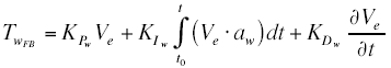
where aw = 0 when saturation of the available torque is detected, aw = 1 otherwise.
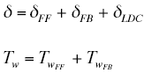
Computation of Controls
Summation of Feed-Forward and Feedback Terms
Simple summation of the feed-forward and feedback terms gives the total demand from the lateral and longitudinal controllers (steer angle and net wheel torque):
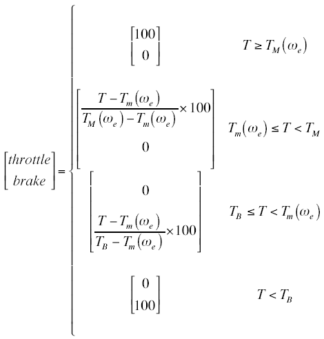
Mapping Net Wheel Torque Demand to Control Actions
Once the required total net wheel torque, Tw has been estimated, basic knowledge of the brake system and driveline are used to identify the necessary control actions (throttle and brake) that must be applied, such that the vehicle delivers the required net wheel torque.
The range of available net wheel torque is related to the available engine torque and the gearing of the vehicle. Neglecting driveline inertia, the ratio of the gearbox and the differential defines the relationship between the net wheel torque (Tw), and the engine torque (Te), at any instant:
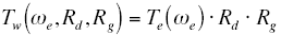
such that the upper and lower limits Tm and TM on the net wheel torque, Tw (we) can be identified from the upper and lower limits on Te (we):
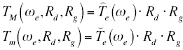
where:
we | Current engine speed (supplied as an input to Machine Control) |
 | Minimum engine output torque (from the user engine map) |
 | Maximum engine output torque (from the user engine map) |
Rd | Mean differential (final drive) ratio (from the basic vehicle knowledge) |
Rg | Gearbox ratio (from the basic vehicle knowledge) |
The maximum brake torque, TB, is assumed to be constant.
Net wheel torque limits as a function of engine speed, and maximum brake torque
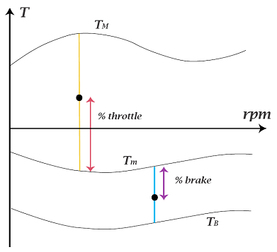
The above figure shows the user-supplied engine model, scaled according to the gearing of the vehicle, to yield:
■The maximum available net wheel torque, TM (normally positive for all we)
■The minimum available net wheel torque Tm (usually negative, especially at high engine speed we, since it includes frictional and pumping losses due to throttling).
To define these limits, you can do either of the following:
■Supply a detailed nonlinear engine map, relating throttle to engine torque,
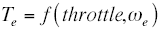
(therefore, adding a third dimension to the figure above)
■Supply only the maximum and minimum engine torques,
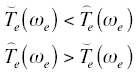
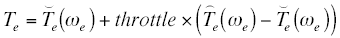
and choose Machine Control to employ a linear model of throttle response:
or

If a throttle map is provided, then this is mathematically inverted, so that the necessary throttle position can be identified from the required net wheel torque Tw, provided it is feasible for the engine to deliver this torque at the current engine speed 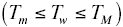 :
:
: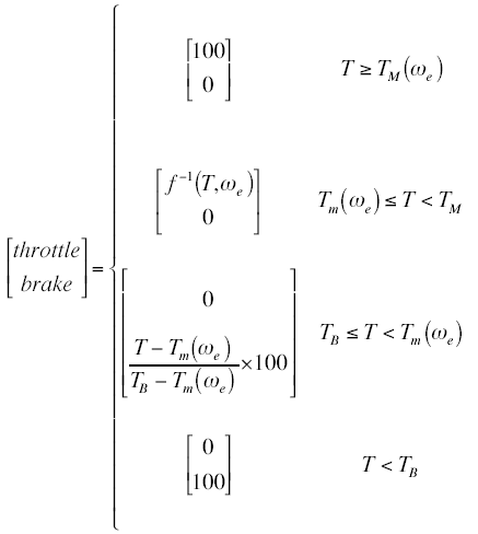
If the linear model is selected, then the feed-forward throttle and brake signals can be determined directly from the required torque:
Control Modulation During Gearshift and Wheel-lift Events
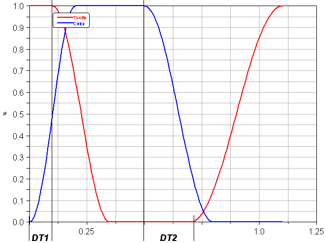
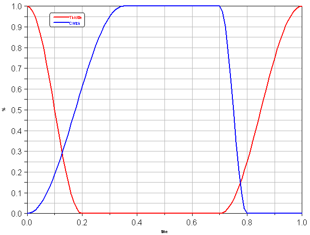
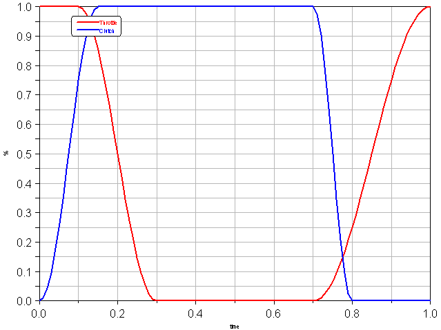
Throttle and clutch modulation during gear-shifting
During a gear-change, the control actuation is open-loop, except for the optional closed-loop rpm control as the clutch is re-engaged. In the following plots, which show the form of the control actions, the origin of the time base is set to be the instant of triggering the gearshift event (see Gear Shifting).
The action of the clutch is determined, and the throttle signal, computed by the feedback and feed-forward controllers, is modulated according to the following parameters:
■Gear change time (not the time of the whole event, but the time for which the clutch is not fully engaged)
■Clutch raise and fall time
■Throttle raise and fall time
■DT1 (the delay between clutch disengagement and throttle release)
■DT2 (the delay between that start of clutch re-engagement and start of throttle reapplication)
The following plot shows the influence of the parameters DT1 and DT2:
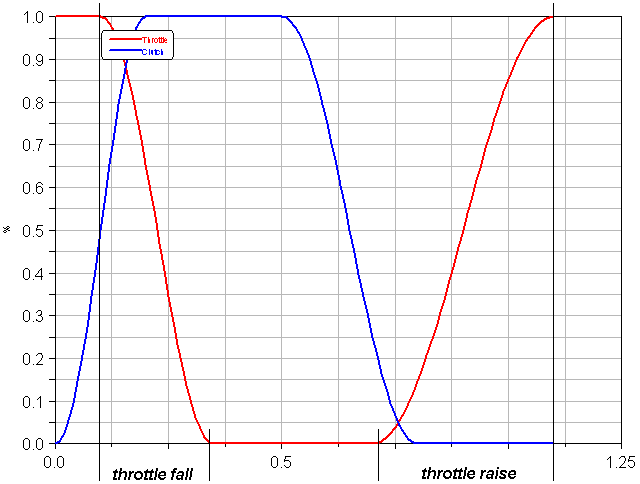
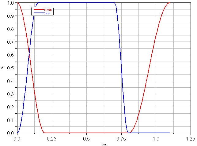
The following plot shows the influence of the throttle raise and fall time parameters:
The following plots show the effect of changing a single parameter from this baseline:
■Changing clutch raise time:
■Changing clutch fall time:
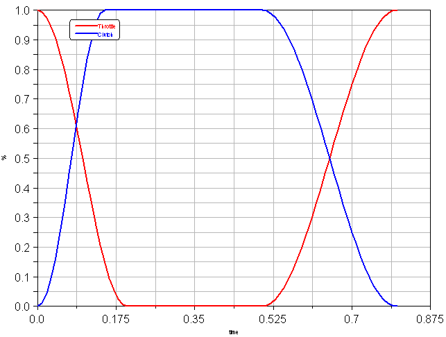
■Changing throttle raise time:
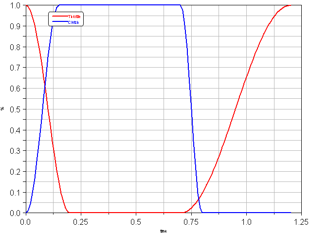
■Changing throttle fall time:
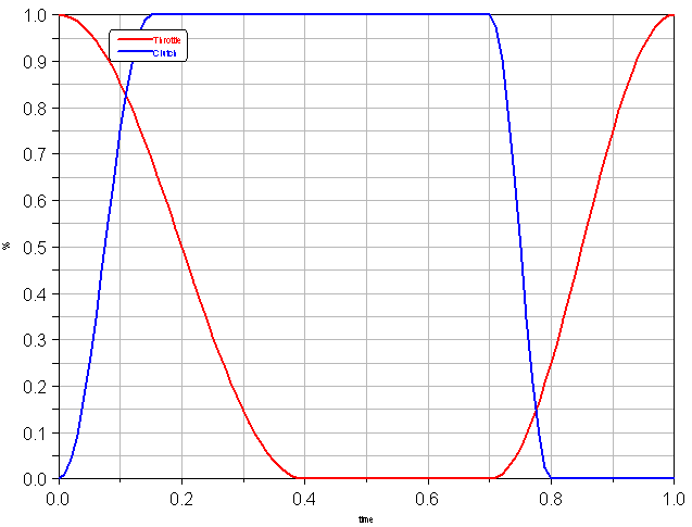
■Changing DT1:
■Changing DT2:
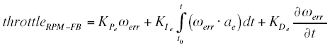
RPM control during clutch re-engagement
During a gear change, between the time when the new gear is selected and the clutch is fully engaged, the engine RPM we can optionally be controlled in a feedback sense, by another classical PID controller with anti-windup. The error on which this controller acts is:
werror = we - wt
where wt is the transmission RPM with which the engine must be synchronized to avoid jerk when the clutch is re-engaged.
This controller acts on the throttle input only.
Wheel-lift compensation
Controller-induced wheel-spin-up or wheel-lock is prevented by detecting when the loads on the driven wheels go to zero (that is, the driven wheels are not in contact with the road). In this case, the throttle and brake are released (set to zero) and the clutch is depressed. The clutch action ensures that when the vehicle lands, the wheels spin up to the correct velocity as quickly as possible.
Driving Machine Design Options to improve computation speed for open loop events
The Driving Machine has several design options that deactivate Adams Solver Driving Machine components and still allow for simulating open loop events. In open loop events the Driving Machine inputs (steering, throttle, brake, gear and clutch) are provided by the user and the controlMethod in the event specifiction is set to 'open'. Removing components from the Adams dataset not needed for the simulation may improve Adams Solver computation speed, which is important for, for example, Real-Time applications utilizing the Fixed Step Integrator.
From the Adams Car GUI, select Adjust → Design Options and choose for Subsystem Name the testrig connected to the assembly (for example, MDI_Demo_Vehicle.testrig). Following three design options are available for Driving Machine State:
■Full Driving Machine - No Adams Solver components are deactivated in the Adams dataset. This default option allows for full functionality of the Driving Machine.
■Open Loop Events - Adams Solver components connected to the Driving Machine are de-activated, but this design option still allows for using End Conditions in the event.
■External Signal Driven - Adams Solver components connected to the Driving Machine are de-activated, but this design option does not allow for using End Conditions in the event.
As an example, the Driving Machine discrete GSE Adams Solver component is not required when simulating open loop events, and will be deactivated for design options 'Open Loop Events' and 'External Signal Driven'. The GSE may have impact on computation time and thus may improve Solver computation speed by removing it from the Adams dataset.
Prior to running the simulation, the Driving Machine state is verified and changed to 'Full Driving Machine' or 'Open Loop Events' if a machine controlled event or end condition is detected in the event specification.