Create Emag AT Force
To create Emag AT Force, there are number of parameters to be entered in following dialog box shown in Figure 26. In this release of Emag AT the force does not have its own ude definition, instead separate adams objects are created, namely mforce for rotor and stator, emf file string variable, torque demand variable and finally all requests.
Main
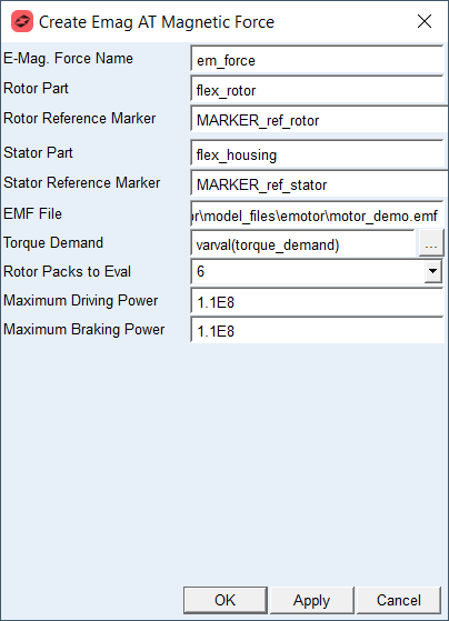
Figure 26 Emag AT Force Create dialog box
All objects belonging to one electromagnetic force are automatically added to one group for better handling such as deletion or deactivation operations, see example on Figure 27
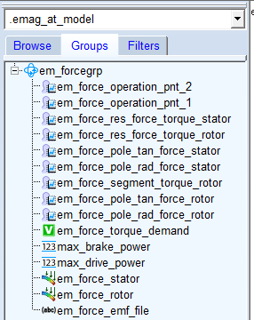
Figure 27 Emag AT Force Group
For the options | Do the following |
|---|---|
Emag Force Name | Enter name for electromagnetic force to be created, the name is populated to rotor and stator mforce, all requests and torque demand and emf file variables. |
Rotor Part | Select existing flexible part representing rotor. |
Rotor Reference Marker | Select reference marker on rotor part. The reference marker should be identical to definition of local coordinate system defined in FE model of rotor, see, Rot. CSYS Point A, Rot. CSYS Point B, Rot. CSYS Point C |
Stator Part | Select existing flexible part representing stator reps. housing. |
Stator Reference Marker | Select reference marker on the stator resp. housing part. The reference marker should be identical to definition of local coordinate system defined in FE model of stator, see, Sta. CSYS Point A, Sta. CSYS Point B, Sta. CSYS Point C |
EMF File | Select electromagnetic force file. |
Torque Demand | Enter value or reference another variable, this entry is controlling the motor output torque. |
Rotor Packs to Eval | Select number of rotor packs to be evaluated in electro motor requests. |
Maximum Driving Power | Enter value of maximum driving power of e-motor characteristics which is used as boundary curve for operating point extrapolation. |
Maximum Braking Power | Enter value of maximum braking power of e-motor characteristics which is used as boundary curve for operating point extrapolation. |
Extended definition:
Rotor/Stator reference Marker
The reference Marker on rotor and stator has to be manually created. It is used to measure the relative angular position and angular velocity of rotor relative to stator. The marker should correspond to local coordinate system of FE model, see Figure 28 and Figure 29
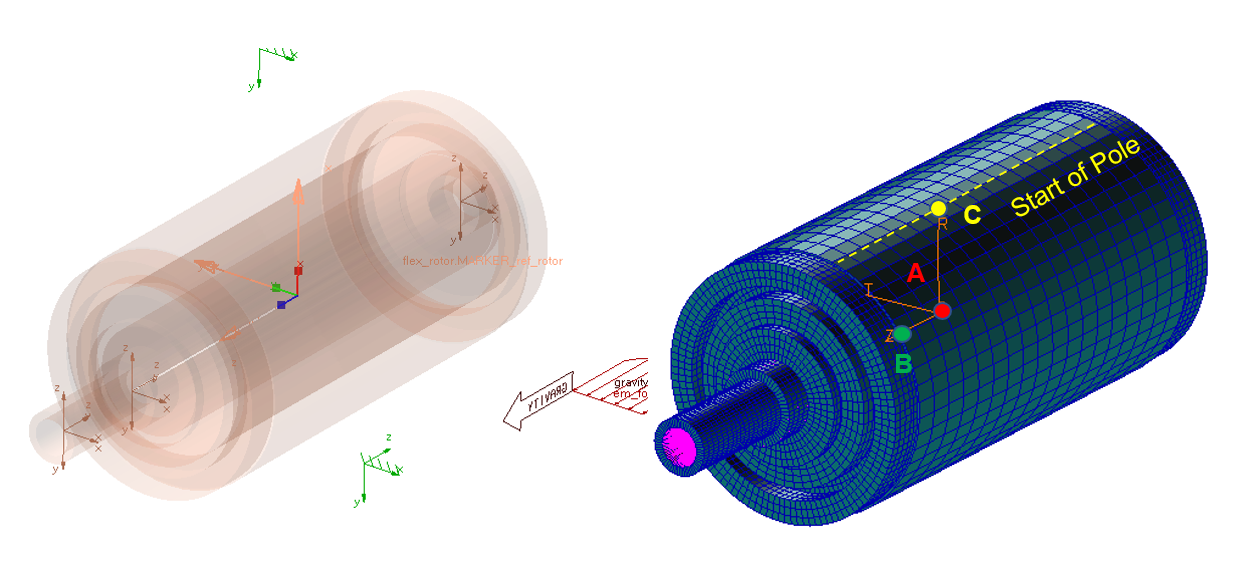 .
.Figure 28 Reference marker on rotor part
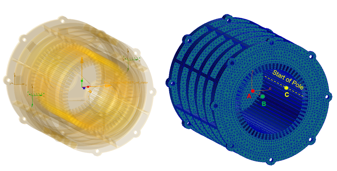
Figure 29 Reference marker on stator part
Maximum driving / braking power
E-motor characteristic is defined by number of discrete operating points (Torque vs. Motor Speed), which do not lay on the maximum power curve – see Figure 35. In case that current e-motor operating point lays beyond field of defined motor characteristic, the values of magnetic force vectors need to be extrapolated so it does not cross the maximum power curve. Since the value of maximum power cannot be determined from preprocessed data stored in *.EMF file, the value needs to be explicitly defined by the user. Figure 30 shows influence of the parameter on computed rotor torque.
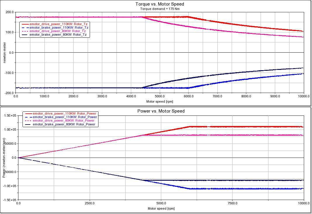
Figure 30 Influence of maximum power on motor characteristics