Create Bearing
Machinery → Create Bearing
Joint Method
An ideal kinematic joint is used to represent the bearing. Constrained degrees of freedom will have no relative motion. This method is useful for basic sizing applications.
For the option | Do the following |
|---|---|
If Radial/Radial-Thrust type is selected, the following options will be displayed: | |
Bearing Name | Enter the bearing name. |
Bearing Location | Enter/Pick the bearing location. |
Axis of Rotation | Specifies the direction of the axis of rotation for the bearing (the bearing's z-axis). Axis of Rotation will define the orientation of the bearing I and J markers as: ■Orientation: Orientation per the entered values in the current rotation sequence specified for the model. ■Pick (Marker): Orientation same as that of the selected marker. ■Global Z: Positive Z of the bearing markers will match positive global Z. ■Global X: Positive Z of the bearing markers will match positive global X. ■Global Y: Positive Z of the bearing markers will match positive global Y. Note: For bearings which take axial loading in one direction, they will resist motion along the negative axial direction (that is, negative z-axis of the bearing I and J markers that are created upon conclusion of this wizard). |
Bearing Geometry Scaling | Use the slider bar to scale the bearing icon geometry size. |
Compliant Method
A force is used to represent the bearing. Simple linear stiffness and damping terms can be applied all the way up to full 6x6 stiffness and damping matrices. This method is useful when the effects of bearing compliance must be considered.
For the option | Do the following |
|---|---|
Linear type is selected, the following options will be displayed: | |
Bearing Name | Enter the bearing name. |
Bearing Location | Enter/Pick the bearing location. |
Axis of Rotation | Specifies the direction of the axis of rotation for the bearing (the bearing's z-axis). Axis of Rotation will define the orientation of the bearing I and J markers as: ■Orientation: Orientation per the entered values in the current rotation sequence specified for the model. ■Pick (Marker): Orientation same as that of the selected marker. ■Global Z: Positive Z of the bearing markers will match positive global Z. ■Global X: Positive Z of the bearing markers will match positive global X. ■Global Y: Positive Z of the bearing markers will match positive global Y. Note: For bearings which take axial loading in one direction, they will resist motion along the negative axial direction (that is, negative z-axis of the bearing I and J markers that are created upon conclusion of this wizard). |
Radial Symmetric | Enter sparse matrix values for stiffness and damping 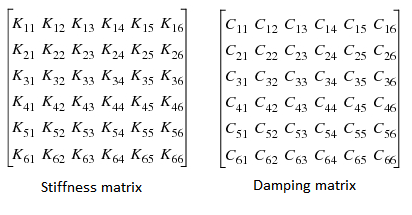 ■Axial Stiffness: Enter stiffness value along axis of rotation, that is, K33. ■Radial Stiffness: Enter stiffness value along radial direction, that is, K11 and K22. ■Bending Stiffness: Enter stiffness value for bending, that is, K44 and K55 ■Axial Damping: Enter damping value along axis of rotation, that is, C33 ■Radial Damping: Enter damping value along radial direction, that is, C11, C22 ■Bending Damping: Enter damping value for bending, that is, C44 and C55 ■Axial Preload: Enter preload value for rotational axis ■Radial Preload: Enter preload value in x,y directions ■Bending Preload: Enter preload value about radial directions ■Torsional Damping: Enter damping value for rotational axis, that is, C66 ■Torsional Stiffness: Enter stiffness value for rotational axis, that is, K66 ■Torsional Preload: Enter preload value along rotational axis |
Full Matrix K11…K66 and C11….C66 | Enter full matrix values (6x6) for each of stiffness and damping table. that is, ■Force/Torque Preload: Define three preload force components and three preload torque components transferred by the field element when the I and J markers are separated/misaligned by the values specified in the Translation at Preload and Rotation at Preload text boxes. The terms are the force components along the x-, y-, and z-axes of the J marker and the torque components about the x, y-, and z-axes of the J marker, respectively. Entering values for Force Preload and Torque Preload is optional and defaults to six zero entries. Mapping of Radial Symmetric and Full Matrix: Force Preload – {radial_preload, radial_preload, axial_preload} Torque Preload – {bending_preload, bending_preload, torsional_preload} ■Translation/Rotation at Preload: Enter the amounts of translational and rotational displacement present in the design position of the model when the specified Force/Torque Preload values are applied. ♦Translation at Preload: defines three reference lengths. This is the nominal (x0, y0, z0) position of the I marker with respect to the J marker, resolved in the J marker coordinate system. ♦Rotation at Preload: defines the reference rotational displacement of the axes of the I marker with respect to the J marker, resolved in the J marker axes (a0, b0, and c0) (specified in radians). If the reference force is zero, then the preload is the same as the free length. Entering preload values is optional; if unspecified the values all default to zero. ■Damping Ratio: To enter a damping ratio that defines the ratio of the damping matrix to the stiffness matrix, select Damping Ratio and enter the value. If you enter a damping ratio, Adams Solver multiplies the stiffness matrix by the ratio to obtain the damping matrix. |
Bearing Geometry Scaling | Use the slider bar to scale the bearing icon geometry size. |
Clearance Method
A force is used to represent the bearing. The force is active only after a radial and/or axial clearance is closed at which point it transitions on sharply according to user-specified parameters.
For the option | Do the following |
|---|---|
Bearing Name | Enter the bearing name. |
Bearing Location | Enter/Pick the bearing location. |
Axis of Rotation | Specifies the direction of the axis of rotation for the bearing (the bearing's z-axis). Axis of Rotation will define the orientation of the bearing I and J markers as: ■Orientation: Orientation per the entered values in the current rotation sequence specified for the model. ■Pick (Marker): Orientation same as that of the selected marker. ■Global Z: Positive Z of the bearing markers will match positive global Z. ■Global X: Positive Z of the bearing markers will match positive global X. ■Global Y: Positive Z of the bearing markers will match positive global Y. Note: For bearings which take axial loading in one direction, they will resist motion along the negative axial direction (that is, negative z-axis of the bearing I and J markers that are created upon conclusion of this wizard). |
Constraint | Depending on the type of bearing selected, the Adams Machinery bearing will provide reaction forces to motion in radial and/or axial directions. One may choose to only apply to the model reaction forces in the directions specified here. 'Radial' type supports 'RADIAL_ONLY' reaction forces. 'Radial Axial' supports 'RADIAL AXIAL BOTH' reaction forces. 'Axial' type supports either 'AXIAL ONLY RIGHT' or 'AXIAL ONLY LEFT'. For example, if user selects 'Global X' as bearing orientation then "Axial Left" means the bearing resists motion along the negative axis (-X) of rotation and 'Axial right' will resist along positive direction of rotation (+X) |
Bearing Type | Select option from ‘Radial’, ‘Axial’ and ‘Radial Axial’ |
Contact Stiffness | Enter a real number that defines the contact stiffness. Once the maximum allowed backlash is reached, Adams uses this parameter to model the contact force between the two parts. |
Contact Damping | Enter a real number that defines the contact damping. Once the maximum backlash is reached, Adams uses this parameter to model the contact force between the two parts. |
Sharpness Factor | Enter a real number that defines the sharpness factor. Once the maximum allowed backlash is reached, Adams uses this value to model the contact force between the two parts. |
Axial Clearance | Enter the real number that defines the maximum clearance allowed in the axial direction. The z-axis of the Coordinate Reference determines the axial direction. |
Radial Clearance | Enter the real number that defines the maximum clearance allowed in the radial direction. The z-axis of the coordinate reference determines the radial direction. |
Diameter | Enter the real number that defines the diameter of the bearing. Adams uses this number to create a graphic for the bearing and to evaluate drag force. Radial or combined load 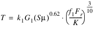 Pure thrust load 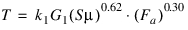 |
Geometry Factor | Enter the real number that defines bearing geometry factor (G1) as mentioned in the equation above. |
Viscosity | Enter the real number that defines lubricant viscosity  |
K factor | Enter the real number that defines the bearing K-factor. The K-factor is the ratio of basic dynamic radial load rating to basic dynamic thrust load rating of a single row bearing. (k1 = Constant being 2.56e-5 for T in N*m, 3.54e-5 for T in lbf*in) |
Spline Property file | Enter Spline property file (sample file is present at $topdir/amachinery/examples/bearing). The f1 coefficient is the combined load factor, which is used to calculate the running torque of the bearing. The spline lets the user describe this coefficient as a function of KFa/Fr. (S = Running speed (rpm)) |
Detailed Method
A force is used to represent the bearing. Using advanced analysis technology from drivetrain simulation software KISSsoft, stiffness is calculated at every step based on the positions and velocities at the bearing location. Damping is based on user-specified factors. This method provides a far more accurate representation of the bearing compliance than the compliant method. It also allows for service life prediction based on industry standards.
For the option | Do the following |
|---|---|
Geometry-bearing | |
Bearing Name | Enter the bearing name. |
Bearing Location | Enter/Pick the bearing location. |
Axis of Rotation | Specifies the direction of the axis of rotation for the bearing (the bearing's z-axis). Axis of Rotation will define the orientation of the bearing I and J markers as: ■Orientation: Orientation per the entered values in the current rotation sequence specified for the model. ■Pick (Marker): Orientation same as that of the selected marker. ■Global Z: Positive Z of the bearing markers will match positive global Z. ■Global X: Positive Z of the bearing markers will match positive global X. ■Global Y: Positive Z of the bearing markers will match positive global Y. Note: For bearings which take axial loading in one direction, they will resist motion along the negative axial direction (that is, negative z-axis of the bearing I and J markers that are created upon conclusion of this wizard). |
Bearing Geometry Scaling | The Adams Machinery detailed Bearing is a force representation. It contains no bodies. So, an icon consisting of simple massless geometry will be created at the bearing location and oriented along the axis of rotation to provide a graphical representation of the bearing in the Adams View graphics window. This scaling factor can be used to adjust the size of the icon geometry. Use the slider bar to scale the bearing icon geometry size. |
Create Bearing | ■From Database Using this option one can obtain input values for the Adams Machinery detailed Bearing from a library of standard catalog bearings from various manufacturers at various sizes. While this library contains over 24,000 different bearings it is by no means a comprehensive listing of all bearings from these manufacturers at any type or size. So, the "Available Bearings" menu may not contain any bearings from certain manufacturers for certain types or sizes. It simply contains those bearings accessible from a library furnished by KISSsoft. One should refer to the bearing manufacturers directly for complete lists of available catalog bearings. To know more about the bearing internal geometry dimensions see the Roller Bearing Internal Geometry section. Note: 1. Even while using this option to populate the input fields on this page, the user can always selectively manually overwrite any of the values. 2. Some bearing names shown in the "Available Bearings" list may have special characters such as an asterisk (*) next to them. These indicators come from the manufacturer's catalog. Please refer to the manufacturer for the meaning. These bearings are not treated any differently by the analysis within Adams Machinery Detailed Bearing. ■With User Input This option does not provide any means to populate the input fields on this page other than manual user entry. |
Offset X | Enter Offset along X axis (axial). Offset is a translational difference between the centers of the shaft (rotating part) and housing (fixed part). Enter value in model's length units. |
Offset Y | Enter Offset along Y axis (radial). Offset is a translational distance difference between the centers of the shaft (rotating part) and housing (fixed part). Enter value in model's length units. |
Offset Z | Enter Offset along Z axis (radial). Offset is a translational distance difference between the centers of the shaft (rotating part) and housing (fixed part). Enter value in model's length units. 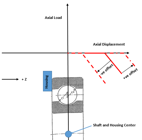 |
Misalignment X | Enter Misalignment along X axis. Misalignment is a rotational (angle) difference between the centers of the shaft (rotating part) and housing (fixed part). Enter value in model's angle units. |
Misalignment Y | Enter Misalignment along Y axis. Misalignment is a rotational (angle) difference between the centers of the shaft (rotating part) and housing (fixed part). Enter value in model's angle units.  |
Constraint | Depending on the type of bearing selected, the Adams Machinery detailed bearing will provide reaction forces to motion in radial and/or axial directions. One may choose to only apply to the model reaction forces in the directions specified here. For example, if the bearing type selected can actually take up radial loading and axial loading in both directions, and one selects "Radial Only" here, then the Adams Machinery detailed bearing will only provide reaction forces in the radial directions; any axial forces calculated will be neglected. "Axial Right" means the bearing resists motion along the positive axis of rotation (+Z axis of the markers created on the shaft and housing parts named "bearing name_marker"). "Axial Left" means the bearing resists motion along the negative axis of rotation (-Z axis of the markers created on the shaft and housing parts named "bearing name_marker"). ■RADIAL ONLY ■RADIAL AXIAL BOTH ■RADIAL AXIAL RIGHT ■RADIAL AXIAL LEFT ■AXIAL ONLY BOTH ■AXIAL ONLY RIGHT ■AXIAL ONLY LEFT |
Bearing Clearance | This defines the bearing's internal clearance. Industry standards define the ranges of values corresponding to C2 (less than normal), C0 (nominal, also known as CN), C3 (greater than nominal), and C4 (greater than C3) based on bearing type and size. The value in the middle of that range is used here and can be found directly in the interface in the diametral or axial clearance fields in the section below. One can also directly specify the clearance value in the model units of length. For more details see section Bearing Internal Clearance and Preload. Note: For bearings which can have both diametral and axial clearance values, this option menu will only set the value for the diametral clearance; one must manually enter the axial clearance. For bearings which have only a diametral or axial clearance (not both), this option menu will set the value for that single clearance value. ■OWN INPUT ■C2 ■C0 ■C3 ■C4 |
If From Database option selected, the following options will be displayed: | |
Manufacturer | Select the manufacturers whose bearings should be included in the search of the bearing library: ■FAG ■TIMKEN ■SKF ■INA ■KOYO ■IBC ■KRW |
Diameter | Enter the diameter to be used in the search of the bearing library. Note that bearings may be indexed by either bore diameter or hub diameter and not necessarily both. ■Bore: Inner diameter of the bearing. ■Hub: Outer diameter of the bearing. |
Show Geometry | Click to see the Bearing geometry diagram explaining the values below. Note: Some parameters are specific to a subset of bearing types. Below is a listing of all parameters. |
Geometry Pedigree | The characteristic geometry values of bearings found in the library have the following pedigree: This data is furnished by KISSsoft. In some cases the values came to KISSsoft directly from the manufacturer (most bearings from IBC and KRW) and in other cases KISSsoft has derived the values (most bearings from other manufacturers). In all cases these values are intended to be used only as an approximate guide. A truly accurate and definitive set of values for any bearing can only come from direct communication with the bearing manufacturer. Whenever a bearing is selected from the Available Bearings menu, one of the following three Geometry Pedigree descriptions will be displayed: ■From manufacturer: Bearing geometry values come directly from the manufacturer. ■Derived from load ratings: Bearing geometry values are derived. This derivation is an approximation made by applying the dynamic and static load ratings as listed by the manufacturer and a reasonable estimate of the rolling elements' pitch diameter to a series of formulae found in ISO 76 and ISO 281. ■Unrealistic: Bearing geometry data has been derived from load ratings (as described above) and this process has resulted in a set of values that is not physically realistic (for example, sufficiently large and numerous rolling elements that could not physically fit in a circle of the specified diameter). No such check is made on bearing data that comes directly from the manufacturer. |
Ball/Roller Pitch Diameter (Dpw) | Enter ball/roller pitch diameter. |
Ball/Roller Diameter (Dw) | Enter ball/roller diameter. |
Effective Roller Length (Lwe) | Enter the effective roller length. |
Roller Radius (Rp) | Enter the roller radius. |
Distance to Roller Crown (Lwc) | Enter the distance to roller crown. |
Roller Centerline Distance (a) | Enter the roller centerline distance. |
Number of Balls/Rollers (Z) | Enter number of balls/rollers. |
Inner Raceway Radius (ri) | Enter the inner raceway radius. |
Outer Raceway Radius (ro) | Enter outer raceway radius. |
Pressure Angle | Enter the pressure angle. |
Diametral Clearance | Enter the diametral clearance in the model units of distance. This is designed diametral clearance; the distance the two rings can move radially without contact. Use positive values to define some free play between the inner and outer rings, use negative values to specify a radial pre-tension. For more details see section Bearing Internal Clearance and Preload. |
Axial Clearance | Enter a positive value to define the axial clearance in the model units of distance. This is designed axial clearance; the distance the two rings can move axially without contact. Do not enter a negative value. For more details see section Bearing Internal Clearance and Preload. |
Static Load Rating (C) | Enter static load rating (C) in the model units of force. This value is optional and, itself, doesn't directly influence the calculation. However, for many bearings in the pre-defined database, the internal geometry dimensions (which do directly influence the calculation) are derived from this value and the dynamic load rating. So, for database bearings this value is shown. For more details on the derivation of bearing internal dimensions see sections Approximation of the inner geometry and Load Ratings. |
Dynamic Load Rating (C0) | Enter dynamic load rating (C0) in the model units of force. This value is optional and, itself, doesn't directly influence the calculation. However, for many bearings in the pre-defined database, the internal geometry dimensions (which do directly influence the calculation) are derived from this value and the static load rating. So, for database bearings this value is shown. For more details on the derivation of bearing internal dimensions see sections Approximation of the inner geometry and Load Ratings. |
Fatigue Load Limit (Cu) | Enter fatigue load rating (Cu) in the model units of force. This value is optional and is specified by the bearing manufacturer. If this is not known, you can calculate them with the approximate formula as defined in ISO 281. ISO 281 also introduces a service life correction factor, aiso which allows you to compute a corrected nominal service life (Lnm) as follows: Lnm = a1 aiso L10 This service life correction factor provides an estimate of the influence of lubrication and contamination on bearing service life, also taking into account steel fatigue limit. For more details see sections Calculation of service life based on the bearing inner geometry (ISO/TS 16281) and Load Ratings. |
Connections-bearing | |
Shaft | Select the rotating part which bearing connects. |
Housing | Select the relatively stationary part which the bearing connects. |
The force returned by the Adams Machinery detailed Bearing has a stiffness component (returned by the KISSsoft calculation) and a damping component calculated by Adams. The damping component resists the velocity and is modeled as a damping coefficient multiplied by velocity. The damping coefficient is determined by multiplying the square root of the instantaneous stiffness by a damping factor. Damping factors can be specified below. Some experience suggests that a reasonable range of damping factors for the bearings provided in the KISSsoft library is 0.1-0.5. | |
Impose Motions | ■On ■Off |
Force Display | ■None ■On Shaft ■On Housing ■Both |
Axial Damping Factor | Enter the axial damping factor (translational along the axis of rotation). |
Bending Damping Factor | Enter the bending damping factor (angular about the axes perpendicular to the axis of rotation). |
Radial Damping Factor | Enter the radial damping factor (translational about the axes perpendicular to the axis of rotation). |
Torsional Damping Factor | In the torsional sense (velocity about the axis of rotation of the bearing), since there is no stiffness, more traditional damping can be applied to represent friction in the bearing: ■None: No velocity-dependent force is applied in this direction. ■Coefficient: Enter a damping coefficient (torque in this direction will oppose the sign of the velocity and have a magnitude equal to the value of this coefficient multiplied by the velocity). ■User Function: Enter any valid function to represent torque about the positive axis of rotation (+Z axis of the markers created on the shaft and housing parts named "bearing name_marker"). |