Create Cable
Machinery → Create Cable
Anchor Layout
For the option | Do the following |
|---|---|
Cable System Name | Enter system name. |
Number Of Anchors | Enter number of anchors. Enter either zero for a "closed" cable, or 2 or more for an "open" cable system. A single anchor system is not allowed; so, entries of 1 are not allowed. Note: Maximum number of anchors is 10. |
Anchor 1/2.... | |
Name | Enter name of the anchor. |
Location | Enter/Select location. |
Connection Part | Enter/Select part that will support the anchor by a fixed joint. |
Winch | Enter a state variable that defines the winch output cable length. For the discretized cable method, the state variable must deliver a positive value. For the simplified cable method the value can be either positive or negative. A positive value indicates that cable is winched to the system (total cable length is increasing), a negative value indicates that cable is winched from the system (total cable length is decreasing). |
Pulley Properties

For the option | Do the following |
|---|---|
Number Of Pulley_Properties | Enter number of pulley_properties. Note: It should be >0 and <=5 |
Number Of Pulley 1/2.... | |
Pulley Property Name | Enter pulley property name. |
Dimensions | |
Width | Enter width (see figure). width > 2*(radius*COS(angle)+(depth-radius*(1-SIN(angle)))*TAN(angle)) |
Depth | Enter depth (see figure). depth > radius*(1-SIN(angle)) |
Radius | Enter radius (see figure). |
Angle | Enter angle (see figure). |
Contact Parameters | |
Hertz K | Enter Hertz contact formulation stiffness coefficient. These parameters define the typical Adams contact model described by the IMPACT function. |
Hertz E | Enter Hertz contact formulation exponent. These parameters define the typical Adams contact model described by the IMPACT function. The value should be >1. |
Hertz Cm | Enter Hertz contact formulation maximal damping (penetration depth setting is automated). These parameters define the typical Adams contact model described by the IMPACT function. |
Friction Mu | The dynamic coefficient of friction between the pulley and cable. Note: Only sliding friction is considered here; so, no static coefficient of friction is present. |
Friction Vt | The relative velocity between the pulley and cable at which the full coefficient of friction, Friction Mu, is applied. That is, mu = 0 when the pulley-cable relative velocity = 0 and it approaches the value provided for "Friction Mu" as the pulley-cable relative velocity approaches "Friction Vt". |
Pulley Layout
For the option | Do the following |
|---|---|
Number Of Pulleys | Enter number of pulleys. You must define at least two pulleys when number of anchors was set to zero. Note: It should be >0 and <=30 |
Number Of Pulley 1/2.... | |
Layout | |
Name | Enter name of the pulley. |
Location | Enter the pulley location. |
Axis Of Rotation | Reference Axis of Rotation can be one of the following: ■Orientation ■Pick (Marker) ■Global Z ■Global X ■Global Y |
Angular Mis-Alignment (X) | Enter the rotation value of the pulley about the X axis of the Reference Axis of rotation. |
Angular Mis-Alignment (Y) | Enter the rotation value of the pulley about the Y axis of the Reference Axis of rotation. |
Flip Direction | Use to flip the sense of axis of rotation that will be used to wrap the cable around the pulley. |
Diameter | Enter external diameter of pulley (see figure). diameter > 8*depth |
Pulley Property | Enter/Select pulley property name. |
Material (Tab) By default, Adams View calculates the mass and inertia for a rigid body part based on the part's geometry and material type. The geometry defines the volume and the material type defines the density. The default material type for rigid bodies is steel. You can change the material type used to calculate mass and inertia or simply specify the density of the part. If you do not want Adams View to calculate mass and inertia using a part's geometry, material type, or density, you can enter your own mass and moments of inertia. It is possible to assign zero mass to a part whose six Degrees of freedom you constrain with respect to parts that do have mass. You should not assign a part zero mass, however. Any part that has zero mass and translational degrees of freedom can causes simulation failure (since a = F/m). Therefore, we recommend that you assign finite masses and inertias to all parts. In addition, a part without mass cannot have mass moments of inertia. Learn about Methods for Calculating Mass Properties. | |
Define Mass By | ■Geometry and Density You can change the material type used to calculate mass and inertia or simply specify the density of the part. ■Geometry and Material Type ■The geometry defines the volume and the material type defines the density. ■User Input ■If you do not want Adams View to calculate mass and inertia using a part's geometry, material type, or density, you can enter your own mass and moments of inertia. |
If you select Geometry and Density, the following options will be displayed: | |
Density | Enter the density value. |
If you select User Input, the following options will be displayed: | |
Mass | Enter the mass of the pulley part. |
Ixx | Enter inertia with respect to X axis. |
Iyy | Enter inertia with respect to Y axis. |
Izz | Enter inertia with respect to Z axis. |
If Off-Diagonal Terms option selected, the following options will be displayed: | |
Ixy | Enter XY cross inertia. |
Izx | Enter ZX cross inertia. |
Iyz | Enter YZ cross inertia. |
Connection (Tab) | |
Connection Type | ■Cylindrical ■Revolute ■Fixed ■None |
Connection Part | Enter/Select part that will support the pulley by previous connection type. |
Cable
For the option | Do the following |
|---|---|
Number Of Cables | Enter number of cables. Note: It should be >=0 and <=5 |
Number Of Cables 1/2.... | |
Setup | |
Cable Name | Enter name of the cable. |
Begin Anchor | Enter/Select begin anchor name (if any). |
Wrapping Order | Enter/Select the ordered list of pulleys to wrap the cable around between begin and end anchors if any (open cable, closed cable around pulleys if not). |
End Anchor | Enter/Select end anchor name (if any). |
Diameter | Enter cable diameter to be used for reference beam formulation. |
Parameters | |
Density | Enter cable density |
Young’s Modulus | Enter the young's modulus to be used for reference beam formulation. |
Rkx, Rkb, Rkt | The cable gets its stiffness definition derived from the user-entered cross-sectional dimensions and Young's modulus. That derivation is based on beam theory described in Non linear theory section of the BEAM statement describing the Euler-Bernoulli beam formulation. The purpose of these Rkx, Rkb, Rkt inputs is to allow the user a means by which to represent an orthotropic material property. These are multipliers on the stiffness in the axial (Rkx), bending (Rkb) and twisting (Rkt) directions. Commonly for cables you have something that bends much more easily than it stretches and twists somewhat more easily than it stretches. So to do that set Rkx = 1.0 and Rkb << 1.0 and Rkt < 1.0. Note: For the Simplified method cable only Rkx has an influence. Rkb and Rkt are ignored for the simplified cable. Refering to the Linear Theory section of Beam, the stiffness matrix looks like below: 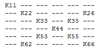 And the multipliers (Rkx, Rkb and Rkt) on the stiffness are specified as: 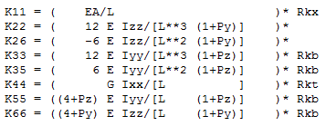 |
Rkx: Ratio of longitudinal stiffness with respect to reference beam formulation. For details on the beam formulation used, please refer to the Using the FORMULATION=LINEAR option and Using the FORMULATION=NONLINEAR option sections of the BEAM statement describing the Euler-Bernoulli beam formulation used here. Rkx is used as multiplier for component K11 in Beam formulation. Rkb: Ratio of bending stiffness with respect to reference beam formulation. For details on the beam formulation used, please refer to the Using the FORMULATION=LINEAR option and Using the FORMULATION=NONLINEAR option sections of the BEAM statement describing the Euler-Bernoulli beam formulation used here. Rkb is used as multiplier for component K33,K35,K55,K66 in Beam formulation. Note: Rkb applies only to the Discretized method cable. It is ignored for the Simplified cable. Rkt: Ratio of torsion stiffness with respect to reference beam formulation. For details on the beam formulation used, please refer to the Using the FORMULATION=LINEAR option and Using the FORMULATION=NONLINEAR option sections of the BEAM statement describing the Euler-Bernoulli beam formulation used here. Rkt is used as multiplier for component K44 in Beam formulation. Note: Rkt applies only to the Discretized method cable. It is ignored for the Simplified cable. | |
Damping Ratio | Damping ratio is applied as multiplier of stiffness to define cable damping. 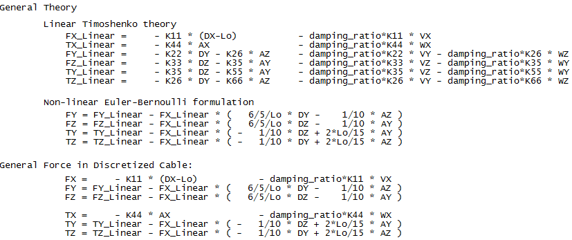 |
Velocity | Velocity is used to define initial cable velocity. Sign convention is such that positive velocity will tend to move the cable in the direction from the start anchor toward the end anchor; in systems without anchors the velocity will tend to move the cable through the pulleys in the sequence specified for wrapping. |
Preload | Preload is used to define initial cable preload. |
Method | ■Simplified The simplified cable provides a very fast solution which generates accurate loads on the pulleys as long as cable mass and inertia effects are negligible with respect to transmission effect. Cable tension, cable-to-pulley contact (including friction) and winching length effects are captured. Pulleys and anchors must be initially co-planar but can translate and rotate out-of-plane and disengage during the simulation. For more details regarding this method, see Simplified section in the general user guide. ■Discretized The cable is discretized with appropriate parts, joints and forces (mass, inertia, beam-formulation-based longitudinal, bending and torsional stiffnesses). There is also an inline joint primitive between each cable part in order to provide control over the bending angle and transverse displacement at the ends of each beam. Contact with pulleys is applied with forces using an optimized analytical formulation (sphere/ cylinder) in the plane together with an appropriate lateral guidance approximation. For more details regarding this method, see Discretized section in the general user guide. |
If simplified method is selected, the following options will be displayed: | |
Solver | ■Auto (to automate the setting of solver parameters) ■none (to keep user setting of solver parameters) |
Gravitational Force | ■on (default to approximate the effect of cable weight) ■off |
Inertia | ■on (default to approximate the effect of cable inertia) ■off |
Disengagement | ■on (default to simulate possible cable disengagement from pulleys) ■off |
If discretized method is selected, the following options will be displayed: | |
Solver | ■Auto (to automate the setting of solver parameters) ■none (to keep user setting of solver parameters) |
Gravitational Force | ■on (default to approximate the effect of cable weight) ■off |
Inertia | ■on (default to approximate the effect of cable inertia) ■off |
Disengagement | ■on (default to simulate possible cable disengagement from pulleys) ■off |
Mesh | Enter the ratio of smallest pulley diameter to be used to define cable elements length. 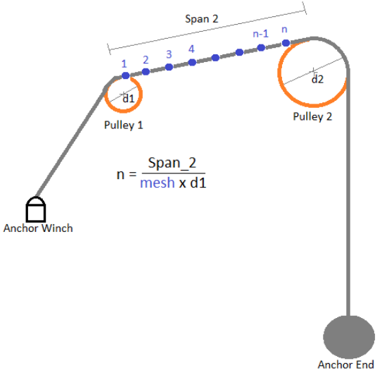 |
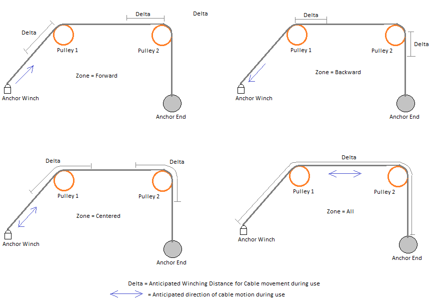
Zone | ■forward (to anticipate possible contact only for cable moving forward) ■centered (to anticipate possible contact centered forward and backward around local pulley) ■backward (to anticipate possible contact only for cable moving backward) ■all (default to anticipate all possible contact) |
Delta | Enter length of cable to anticipate contact simulation with respect to zone. |
 | |
Output | |
Pulley Results | Enter anchor/pulley ids (1 being the first anchor for open cable, or the first pulley for closed cable) to get the following output: ■Anchors ■Force components in connection ■Pulleys ■Force components in connection ■Connection linear displacement and velocity along local Z axis ■Connection angular displacement and velocity around local Z axis ■Wrapped angle and length ■Cable longitudinal velocity (absolute velocity of cable) ■Cable sliding velocity (relative velocity of cable with respect to pulley) ■Contact force density (per unit of length) Forces (anchors and pulleys): All the components of force acting in the attachment joint of the element (either anchor or pulley). ■MAG, X, Y, Z, AMAG, R1, R2, R3 Data (pulleys only): ■Pulley_DZ: this is the relative displacement of the pulley joint with respect to local Z axis. ■Pulley_VZ: this is the relative velocity of the pulley joint with respect to local Z axis. ■Pulley_AZ: this is the relative angular displacement of the pulley joint with respect to local Z axis. ■Pulley_WZ: this is the relative angular velocity of the pulley joint with respect to local Z axis. ■Wrapped_Angle: this is the angle of the pulley that is wrapped with cable. ■Wrapped_Length: this is the length of cable that is wrapped on the pulley. ■Cable_VX: this is the average longitudinal absolute velocity of the cable on the pulley. ■Sliding_VX: this is the average longitudinal sliding velocity of the cable on the pulley. ■Contact_Density: this is the linear density of the normal contact force of the cable on the pulley (unit is "force per length"). |
Span Results | Enter span ids (1 being the span between the first anchor and the first pulley for open cable, or the span between the first pulley and second pulley for closed cable). ■Span length ■Span transverse displacement along local Y and Z axis ■Span tension force ■Color coding for the cable Data: ■Span_Length: this is the length of the cable between a pair of elements (either anchor/pulley or pulley/pulley). ■Span_DY and Span_DZ: these are the two transverse displacements of the cable between a pair of elements (either anchor/pulley or pulley/pulley) measured at the middle of the geometrical tangent line with respect to the following reference frame: ■Local: ♦X axis is aligned with the tangent line ♦Z axis stays in the plane of X axis and pulley rotational axis ♦Y axis stays in the rotation plane of the pulley ■Global: ♦X, Y and Z axis are aligned with the ground reference frame ■Span_Tension: this is the average longitudinal tension of the cable between a pair of elements (either anchor/pulley or pulley/pulley). ■Color coding for the cable: ■White color (A): Span over Pulley pitch circle diameter. ■Yellow color (B): Approach span from pulley’s outer diameter to the point of tangency. ■Blue color (C): Recede span from the point of tangency to pulley’s outer diameter. ■Green color (D): Straight span |
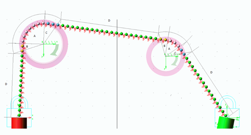 Note: Straight span does not start from point of tangency on pitch circle diameter of pulley as cable may interfere with pulley groove. Hence, approach and recede cable path remains in pulley plane. | |