Create Motor
Machinery → Create Motor
For the option | Do the following |
|---|---|
Motor Method | |
Method | ■Analytical Motor torque is defined by equation sets specific to the type of motor selected. ■Curve Based Motor torque is defined by a user-provided torque versus speed curve. ■External The motor is modeled externally in any software supported by Adams Controls. It is incorporated into the Adams analysis via either external system library (ESL) import mode or co-simulation mode. |
Motor Type | |
Type | ■AC Synchronous An AC synchronous motor is a motor in which, at steady state, the rotation of the shaft is synchronized with a frequency of the supply current. The rotation is exactly equal to an integral number of AC cycles. Synchronous motors contain electromagnets on the stator of the motor that create a magnetic field which rotates in time with the oscillations of the line current. The rotor turns in step with this field, at the same rate. ■DC The DC motor is a mechanically commuted motor. Powered by a DC electric source, current in the rotor is switched by the commutator. Both series and shunt type DC motors can be represented with this option. ■BLDC BLDC motors are also known as electronically commuted motors. They are synchronous motors which are powered by a DC electric source via an integrated switching power supply, which produces an AC electric signal to drive it. For motors designed specifically to be operated in a mode where they are frequently stopped with the rotor in a defined angular position use the stepper motor option instead. ■Stepper A stepper motor is a brushless, synchronous electric motor that converts digital pulses into mechanical shaft rotation. Every revolution of the stepper motor is divided into a discrete number of steps and the motor must be sent a separate pulse for each step. Stepper motors provide a means for precise positioning and speed control without the use of feedback sensors. |
Motor Connections | |
Motor Name | Enter the motor name. |
Motor | ■New This method will be used, if location will be selected in the Working Grid or by entering a coordinate values in the Location Text Box or by Clicking a point from the working Grid. ■Replace Motion This method will be used if location of the motor can be replaced by an existing Motion already defined in Model. If Replace Motion Option is selected from the Motor Combo Box, a new Combo box (Motion Name) appears and lists all existing motion in the current model. The Desired Motion can be selected from the list. ■Motion Name ♦motion_r1 ♦motion_r2 ♦motion_r3 ■Replace Torque This method will be used if location of the motor can be replaced by an existing Torque (SForce) already defined in Mechanism. If Replace Torque Option is selected from the Motor Combo Box, a new Combo box (Torque Name) appears and lists all existing Torques (SForce) in the current model. The Desired SForce can be selected from the list. ■Torque Name ♦SFORCE_1 ♦SFORCE_2 ♦SFORCE_3 |
Direction | Select the direction of rotation of the motor ■CW (Clock Wise) ■CCW (Counter Clock Wise) 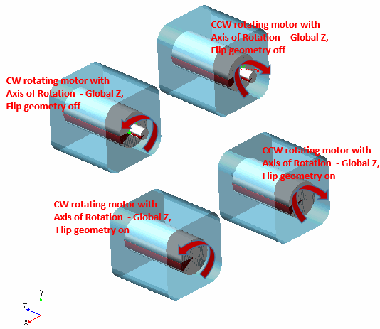 |
Location | Enter motor location. |
Axis of Rotation | ■Orientation – Co ordinates are entered ■Pick – Co ordinates are selected from the Working Grid ■Global X – X Axis as Axis of the Motor ■Global Y – Y Axis as Axis of the Motor ■Global Z – Z Axis as Axis of the Motor |
Rotor Attach Part | Connect the Rotor and Stator of the Motor to the parts of the Model or the Ground. ■Fixed ■Compliant ■None Note: Rotor cannot be attached to the Ground as it cannot be stationary. |
If compliant is selected, the following options will be displayed to define the connection between the Rotor and its attach part: | |
Radial Stiffness Kx | Enter the translational stiffness of the compliant connection in the two radial directions (that is, perpendicular to the axis of rotation of the rotor). |
Axial Stiffness Kz | Enter the translational stiffness of the compliant connection in the axial direction (that is, along the axis of rotation of the rotor). |
Bending Stiffness KTx | Enter the rotational stiffness of the compliant connection about the two radial axes (that is, perpendicular to the axis of rotation of the rotor). |
Torsional Stiffness KTz | Enter the rotational stiffness of the compliant connection in the torsional direction (that is, about the axis of rotation of the rotor). |
Damping Ratio | Enter the damping ratio. To determine the damping coefficient in each direction of the compliant connection this damping ratio will be multiplied by each of the stiffness values. |
Stator Attach Part | ■Fixed ■Compliant ■None |
If compliant is selected, the following options will be displayed to define the connection between the Stator and its attach part: | |
Radial Stiffness Kx | Enter the translational stiffness of the compliant connection in the two radial directions (that is, perpendicular to the axis of rotation of the rotor). |
Axial Stiffness Kz | Enter the translational stiffness of the compliant connection in the axial direction (that is, along the axis of rotation of the rotor). |
Bending Stiffness KTx | Enter the rotational stiffness of the compliant connection about the two radial axes (that is, perpendicular to the axis of rotation of the rotor). |
Torsional Stiffness KTz | Enter the rotational stiffness of the compliant connection in the torsional direction (that is, about the axis of rotation of the rotor). |
Damping Ratio | Enter the damping ratio. To determine the damping coefficient in each direction of the compliant connection this damping ratio will be multiplied by each of the stiffness values. |
Force Display | Select the part(s) on which a force vector for the load in the connection should be displayed. |
Flip Geometry | Flip (Rotate) the geometry 180 degrees from the current position. |
Motor Geometry | |
Create Rotor Stator Parts | All the parameters listed below will be ignored by checking off. |
Rotor Length | Enter the length of the cylinder geometry to be created on the rotor part. This Parameter is mainly for Visualization Purpose. The Value entered here is used to create the Motor Model in the ADAMS GUI. It is optionally used to calculate the Inertia of the Rotor when Density or Material Property is entered. |
Rotor Radius | Enter the diameter of the cylinder geometry to be created on the rotor part. This Parameter is mainly for Visualization Purpose. The Value entered here is used to create the Motor Model in the ADAMS GUI. It is optionally used to calculate the Inertia of the Rotor when Density or Material Property is entered. |
Stator Length | Enter the length of the box geometry to be created on the stator part (that is, the dimension parallel the rotor axis of rotation). This Parameter is mainly for Visualization Purpose. The Value entered here is used to create the Motor Model in the ADAMS GUI. It is optionally used to calculate the Inertia of the Rotor when Density or Material Property is entered. |
Stator Width | Enter the width of the box geometry to be created on the stator part. (Not cross-section will be a square; so, this value will used for both dimensions perpendicular to the rotor axis of rotation). This Parameter is mainly for Visualization Purpose. The Value entered here is used to create the Motor Model in the ADAMS GUI. It is optionally used to calculate the Inertia of the Rotor when Density or Material Property is entered. |
Mass and Inertia (Rotor and Stator) By default, Adams View calculates the mass and inertia for a rigid body part based on the part's geometry and material type. The geometry defines the volume and the material type defines the density. The default material type for rigid bodies is steel. You can change the material type used to calculate mass and inertia or simply specify the density of the part. If you do not want Adams View to calculate mass and inertia using a part's geometry, material type, or density, you can enter your own mass and moments of inertia. It is possible to assign zero mass to a part whose six Degrees of freedom you constrain with respect to parts that do have mass. You should not assign a part zero mass, however. Any part that has zero mass and translational degrees of freedom can causes simulation failure (since a = F/m). Therefore, we recommend that you assign finite masses and inertias to all parts. In addition, a part without mass cannot have mass moments of inertia. ■Learn about Methods for Calculating Mass Properties. | |
Define Mass By | ■User Input If you do not want Adams View to calculate mass and inertia using a part's geometry, material type, or density, you can enter your own mass and moments of inertia. ■Geometry and Density You can change the material type used to calculate mass and inertia or simply specify the density of the part. ■Geometry and Material Type The geometry defines the volume and the material type defines the density. |
If you select User Input, the following options will be displayed: | |
Rotor Mass | Enter the mass of the rotor part. Rotor is the non-stationary part of electric motor which rotates because the wires and magnetic field of the motor. |
Stator Mass | Enter the mass of the stator part. The stator is the field magnet, interacting with the armature to create motion receiving its influence from moving field coils on the rotor. |
Rotor/Stator Inertia: Enter the mass-moments of inertia for the rotor and stator parts: See section About Entering Mass Moments of Inertia for more information. | |
The parts are located at the center of the motor, with the z-axis as the rotational axis. | |
Ixx/Iyy/Izz | Enter the values that define the principal mass-inertia components of the rotor/stator part. |
Ixy/Izx/Iyz | Enter the values that define the deviational (cross-product) mass-inertia components of the rotor/stator part. |
If you select Geometry and Density, the following options will be displayed: | |
Density | Enter the density value. |
If you select Geometry and Material Type, the following options will be displayed: | |
Material Type | Enter the material type to be used inertia calculation |
Inputs
For the option | Do the following |
|---|---|
Curve Based Method | |
Select Spline | Select a predefined spline data of Speed and Torque. |
Enter Spline File | Spline File Name: Select the entry of data of Speed and Torque via external file. For more information, see section Enter Spline File. Note: In .csv file, the independent axis (Angular Velocity) should be in RPM units and the ordinate axis (Torque) units must be as per the model units. |
Create Data Points | This method allows direct entry of data into the table present in the motor wizard. For more information, see section Create Data Points. |
Analytical Method | |
AC Synchronous The torque for an AC Synchronous motor is calculated as, 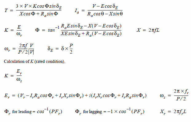 Please see the Torque Angle Calculation () and Pole Slipping adjustment for Torque angle calculation and pole slipping details. Note: In actual implementation Er is calculated as magnitude (Er = SQRT (Re(Er) ^2 + Im(Er) ^2)) and not as complex number. Where: | |
■T = Motor Torque ■V = Supply voltage ■K = BEMF constant ■φ = Power Factor Angle ■δΕ = ElectricalTorque Angle ■δ = Torque Angle ■X = Reactance ■E = Back EMF ■ωr = Rotor angular velocity ■f = Supply Frequency ■L = Inductance | ■P = Poles ■Er = Rated Back EMF ■s = Angular velocity ■Vr = Rated Voltage ■Ir = Rated Current ■Ra = Armature Resistance ■φ = Rated Power Factor Angle ■Xr = Rated Reactance ■fr = Rated Frequency ■PFr = Rated Power Factor |
Supply Voltage (V) | Enter supply voltage value. This will corresponds to the voltage provided on the supply terminal to produce a meaningful output. |
Current (Ia) | Enter the value of current that flows through the motor circuit. |
Resistance (Ra) | Enter resistance value of the windings in the Motor. |
Power Factor (φ) | Enter power factor. The power factor of an AC system is defined as the ratio between the real power flowing to the load and the apparent power in the circuit. It is a dimensionless number between -1 and 1. |
Frequency (f) | Enter frequency. The oscillations frequency of alternating current (AC) in an electric power grid transmitted from a power generation plant to the end-user. In the Americas it is typically 60 Hz and in other parts of the world this is 50 Hz |
Inductance (L) | Enter inductance. Inductance is the behavior of a coil in resisting any change of electric current through it. According to Faraday's law, inductance has an influence on the emf generated to oppose a given change in current. |
Poles (p) | Enter poles. This will corresponds to the No. of poles in the stator field of the Motor based on its specification. It is a factor that plays a role to identify the capacity of the motor. |
Synchronous Speed (ωs) | Synchronous speed is the speed of the rotor in which it rotates in step with the rotating magnetic field of the stator. |
DC Shunt Motor The torque for a D.C. Shunt motor is calculated as  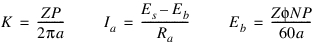 Where ■T = Torque developed in N-m ■K = Torque constant ■  = Flux per pole in Webers = Flux per pole in Webers■Ia = Armature current in Amps ■Z = Number of conductors ■P = Number of Poles ■a = Number of parallel paths in the Armature. ■Es = Source Voltage in Volts ■Eb = Back emf induced in Volts ■Ra= Armature resistance in ohms ■N = Revolutions per Minute | |
Series Motor | |
If Series type is selected, the following options will be displayed: | |
  Where ■T = Torque developed in N-m ■K = Torque constant ■K1 = Series motor constant ■  = Flux per pole in Webers = Flux per pole in Webers■I = Armature current in Amps ■Z = Number of conductors ■P = Number of Poles ■a = Number of parallel paths in the Armature ■Es = Source Voltage in Volts ■Eb = Back emf induced in Volts ■Ra = Armature resistance in ohms ■N = Revolutions per Minute | |
No. of conductors (Z) | Enter number of conductors. |
Flux Per Pole (φ) | Enter flux per pole in Webers. It is the measure of the quantity of magnetism, that is, the total number of magnetic lines of force passing through a specified area in a magnetic field. 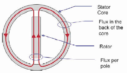 |
Source Voltage (Es) | Enter source voltage. Enter source voltage value. This will corresponds to the voltage provided on the supply terminal to produce a meaningful output. |
No. of Paths (a) | Enter the number of parallel armature Winding paths. Note: Number of parallel paths in armature, a = P for LAP winding and a = 2 for WAVE winding. |
Force Display | Select ON or OFF. This field is used to turn ON or OFF the display of force during simulation. Force display can be turned on for Rotor attached Parts alone or Stator attached Parts alone or Both or None. |
Armature Resistance (Ra) | Enter armature resistance. The Resistance offered by the windings in the moving part of the motor to current flow in the coils. |
No. of Poles (P) | Enter no of poles. This will corresponds to the No of poles in the stator field of the Motor based on its specification. It is a factor that plays a role to identify the capacity of the motor. |
Type | Select DC motor type from the following option: ■Shunt Enter shunt value. This will corresponds to the type of DC motor. A shunt DC motor connects the armature and field windings in parallel or shunt with a common D.C. power source. ■Series Enter series value. This will corresponds to the type of DC motor. A series DC motor connects the armature and field windings in series with a common D.C. power source. |
If Series type is selected, the following option will be displayed: | |
Series Motor Constant (K1) | Enter torque constant for the motor. This represents the proportionality between motor torque and motor current. |
Brushless DC The torque for a BLDC motor is calculated as 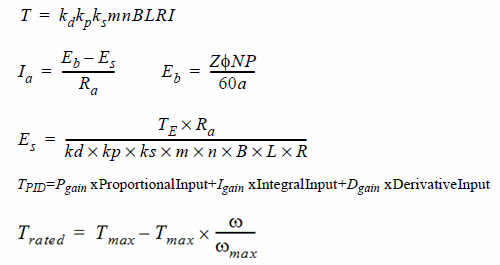 Proportional Input = G x Error For speed control, Error = Desired Speed - Actual Speed For position control, Error = Desired Angular Displacement - Actual Angular Displacement Where: | |
■kd = Distribution Factor ■kp = Coil pitch Factor ■ks = Slot Skew Factor ■m = Number of Teeth per phase ■n = Number of Turns per phase ■B = Strength of the permanent Magnetic field ■L = Length of rotor windings ■R = Radius of Armature ■I = Current in the Motor winding ■T = Torque developed in N-m ■φ = Flux per pole in Webers ■Z = Number of conductors ■P = Number of Poles ■a = Number of parallel paths in the Armature ■Es = Source Voltage in Volts | ■Eb = Back emf induced in Volts ■Ra = Armature resistance in ohms ■N = Revolutions per Minute ■TE = Minimum value of TPID & Trated ■Trated = Rated Torque ■Proportional Input = Error from difference between actual and desired speed (or angle) of the rotor ■Integral Input = Integral of Proportional Input ■Derivative Input = Derivative of Proportional Input ■G = Gain applied to the error ■Pgain = Gain applied to the Proportional Input ■Igain = Gain applied to the Integral Input ■Dgain = Gain applied to the Derivative Input ■Tmax = Maximum Torque ■ωmax = Maximum Angular Velocity ■ω = Actual Angular Velocity of the rotor |
Note: In actual implementation Ia is taken as (Es - Eb)/Ra as modelling implementation needs Ia to be positive and motor will rotate only if Es > Eb, negative value of current in basic equation denotes direction of the current flow. | |
Distribution Factor (kd) | Enter distribution factor (also called Breadth factor). The distribution factor kd reflects the fact that the winding coils of each phase are distributed in a number of slots. Note: It is one of the winding factor that needs to be adjusted for the peak magnetomotive force (mmf) and the winding generated flux which directly leads to adjustments to the peak developed torque of the BLDC motor. |
Coil Pitch Factor (kp) | Enter coil pitch factor (also called Chording factor or Coil-span factor). The pitch factor kp reflects the fact that windings are often not fully pitched, that is, the individual turns are reduced in order to decrease the length of the end-turns and do not cover a full pole-pitch (also called Chorded). Note: It is one of the winding factor that needs to be adjusted for the peak magnetomotive force (mmf) and the winding generated flux which directly leads to adjustments to the peak developed torque of the BLDC motor. |
Slot Skew Factor (ks) | Enter skew factor. The skew factor ks reflects the fact that the winding is angularly twisted, which results in an angular spread and reduced emf. |
Teeth per Phase Count (m) | Enter the number of teeth per phase present in the motor. |
No of Turns per Phase (n) | Enter the number of turns per phase in the armature winding. |
Armature Resistance (Ra) | Enter armature resistance. The Resistance offered by the windings in the moving part of the motor to current flow in the coils. |
No. of Poles (P) | Enter number of poles. This will corresponds to the number of poles in the stator field of the Motor based on its specification. It is a factor that plays a role to identify the capacity of the motor. |
Strength of PM Field (B) | Enter strength of permanent magnetic field of the stator. |
Length of the Rotor Windings (L) | Enter the effective length of rotor windings. |
Radius of the Armature (R) | Enter the radius of armature winding. |
Flux Per Pole (φ) | Enter flux per pole. It is the measure of the quantity of magnetism, that is, the total number of magnetic lines of force passing through a specified area in a magnetic field. |
No. of Conductors (Z) | Enter number of conductors. |
No. of Paths | Enter the number of parallel armature Winding paths. The number of parallel paths in each phase that connect the coil to the source. |
Maximum Torque (T) | The Maximum torque indicated by the user within which the output torque of the motor is to be controlled. |
Max. Ang. Velocity | The Max. Angular velocity indicated by the user such that Rated Torque = Tmax - Tmax * (Actual Angular Velocity/ Max. Angular Velocity). |
Control Method | Select method from the following options: ■Speed Control - Controls Output speed of the rotor shaft based on user spline input. ■Position Control - Controls Angular displacement of the rotor shaft based on user spline input. |
Enter Spline File | The spline is the input file (CSV) by the user which contains data as speed vs time or angle vs time based on control method. Note: In .CSV file, the X-axis data and the Y-axis data should be as per the model units. |
Friction Torque | This is a constant opposing torque and does not vary with velocity. |
Damping Coefficient | This is specified as a constant which is multiplied by angular velocity to get the damping torque. It represents the combined electromagnetic and viscous damping. |
Gain | Specify the gain value used to calculate the speed gain. This speed gain is used in the PID controller. |
P Gain | Specify the Proportional gain applied to the input signal. |
I Gain | Specify the gain applied to the integral of the input signal. |
D Gain | Specify the gain applied to the derivative input. |
Stepper The torque for a Stepper motor is calculated as, 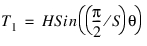 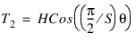 Where ■T1 = Torque on the first winding. ■T2 = Torque on the Secondary winding. ■H = Holding Torque in N-m. ■S = Step Angle in radians. ■θ = Shaft Angle in radians. Note: Stepper Motor can be controlled in the following two ways: ■One Phase on - Full Step Drive: Torque on the first winding (T1) is alone considered. ■Two Phase on - Full Step Drive: Torque on the first winding (T1) and torque on the second winding (T2) are considered. | |
Holding Torque (H) | Enter holding torque. The amount of torque required to remain the motor shaft in a particular position. |
Control Type | Select control type from the following options: ■One Phase On-Full Step Drive ■Two Phase On-Full Step Drive |
Step Angle (S) | Enter step angle. The angle by which the rotor of an stepper motor will rotate when a signal is passed. |
Friction Torque | This is a constant opposing torque and does not vary with velocity. |
Damping Coefficient | This is specified as a constant which is multiplied by angular velocity to get the damping torque. It represents the combined electromagnetic and viscous damping. |
Input Type | To indicate the type of data in the input file. ■PPS vs Time - Pulse per second vs time. The Stepper motor rotates by its step angle when a pulse is received. ■Target Angle vs Time - Target angle is the end position of rotor shaft where the user desires the motor to stop. |
Input File | The spline is the input file (CSV) by the user which contains data as speed vs time or angle vs time based on control method. |
External Method | |
External Method | Select the method from the following options: ■External System Library Import ■Co-Simulation |
If External System Library Import is selected, the following options will be displayed: | |
Plant Input/Output | ■Standard Standard method creates the GSE equation, by importing the External System Library (from MATLAB or Easy5) and using the default input and output state variables. ■User Defined User-Defined method follows the same method as that of Standard method except it allows the user to select input and output state variables. |
If Standard is selected, the following options will be displayed: | |
General State Equation Name | Enter the name of the GSE to be created. |
External System Library | Enter the name of the external system library. If the extension entered is .fmu, Adams will expect an FMU that conforms to the FMI standard. |
Generate External Model Specifications | Click this button to do a plant export using whatever is specified for plant i/o above. This is to create .inf, .m and .fmu files that are particular to this motor. ■Easy5 ■MATLAB ■FMU |
If User Defined is selected, the following options will be displayed: | |
General State Equation Name | Enter the name of the GSE to be created. |
External System Library | Enter the name of the external system library. If the extension entered is .fmu, Adams will expect an FMU that conforms to the FMI standard. |
Import I/O Signals from Existing Controls Plant | Select to display the Database Navigator, where you can select an existing controls plant from which output and input signals are to be imported. |
From Poutput (s) | Select to display the Database Navigator, where you can select an existing poutput from which to import output signals. |
From Pinput (s) | Select to display the Database Navigator, where you can select an existing pinput from which to import input signals. |
Static Hold | Select one of the following: ■Off: Turns static hold off. ■On: Turns static hold on. |
Generate External Model Specifications | Click this button to do a plant export using whatever is specified for plant i/o above. This is to create .inf, .m and .fmu files that are particular to this motor. ■Easy5 ■MATLAB ■FMU |
Use External Library Error Tolerance | Check to apply the error tolerance values of the continuous states of ESL to the GSE during integration. The ESL error tolerance values change the computation of the local integration error that is computed after the corrector as converged. If the estimated error is greater than the specified integration ERROR the integrator rejects the solution. See the INTEGRATOR statement for more details about ERROR. You may want to use this feature to help refine the accuracy of your ESL states, but just like any INTEGRATOR setting, this may require tuning. This feature only applies to the C++ Solver, and only Easy5 models currently report error tolerance values. Error Scale Factor: ■Values > 0 will scale all of the ESL error tolerance values in order to tighten or loosen these values, that is, Final GSE error tolerance = Error Scale Factor * ESL error tolerance ■Values <= 0 will disable using the ESL error tolerance values, and the default computation for the local integration error will be used. |
Information | Check to display verbose information about the general state equation (GSE) that the controls system import created. |
Visibility | This option is only available for External System Libraries of type FMU. Visibility means the FMU runs in interactive mode. Turn it off if you want to run it in batch mode. In order for this option to work in Adams, visibility needs to be supported by the specified FMU. |
Communication Interval | This option is only available for External System Libraries of type FMU. To co-simulation with the FMU you need to specify the communication interval. Sample the FMU at least two times faster than the highest frequency of interest (refer to Nyquist frequency). |
If Co-Simulation is selected, the following options will be displayed: | |
Plant Input/Output | Select one of the following: ■Standard Standard method creates the GSE equation, by importing the External System Library (from MATLAB or Easy5) and using the default input and output state variables. ■User Defined User-Defined method follows the same method as that of Standard method except it allows the user to select input and output state variables. |
If Standard is selected, the following options will be displayed: | |
Target Software | Select the target software from following options: ■Easy5 ■MATLAB ■FMU |
If User Defined is selected, the following options will be displayed: | |
Controls Plant Name | Enter the name of the Controls Plant to be created |
File Prefix | Enter the prefix for the .adm, .cmd, .acf, .m, and .inf files that Adams Controls creates. |
Initial Static Analysis | Select one of the following: ■Yes: Performs initial static analysis. ■No: Does not perform initial static analysis. Note: If Initial Static Analysis is set to Yes and Type is set to linear, Adams Controls performs a static analysis before the linear analysis. Otherwise, Adams Controls performs an initial conditions analysis. |
Initialization Command | Check if you want to enter Adams View or Adams Solver non-time advancing (NTA) commands that you want to have executed before the co-simulation or function evaluation starts. In the text box that appears, enter one NTA command. To execute more than one NTA command, create an .acf file and refer to it using the FILE/COMMAND = command_file_name string in this text box. |
Import Settings From Existing Controls Plant | Select to display the Database Navigator, where you can choose an existing controls plant whose settings you want to use in your current plant. Adams Controls updates the Adams Controls Plant Export dialog box with the appropriate settings. |
Input Signal (s) | Enter names of state variables that you want to use as plant inputs. Select From Pinput to enter state variables from existing plant inputs. |
Output Signal (s) | Enter names of state variables that you want to use as plant outputs. Select From Poutput to enter state variables from existing plant outputs |
Target Software | Select one of the following: ■Easy5 ■MATLAB ■FMU |
Analysis Type | Select one of the following: ■linear - Creates a linearized representation of the model in terms of (A, B, C, D) matrices. A linear analysis is performed. For Target Software of FMU, this option is not supported. ■non_linear - Exports plant for dynamic analysis |
User Defined Library Name | Enter the name of the user-defined library. |
Adams Host Name | Enter the name of the host machine from which the Adams plant is being exported. This host name is used if you choose TCP/IP-based communication to perform co-simulation or function evaluation between Adams and MATLAB, Easy5 or FMU. |
Motor Output
For the option | Do the following |
|---|---|
Multiply | Select from one of the following options: ■Scale Factor ■Step Function ■Expression |
If Scale Factor is selected, the following option displayed: | |
Scale Factor | To multiply the torque value by a constant or a variable. |
If Step_Function is selected, the following options displayed: | |
Start Time | Enter start time. |
End Time | Enter end time. |
Start Value | Enter start value. |
End Value | Enter end value. |
If Expression is selected, the following option displayed: | |
Expression | Define an expression to scale the torque value. |