New Gear AT Element
The creation of a Gear AT Element requires the input of a name, the reference to the property file (cgp-file) and the position and orientation of the gear wheel defined by the reference marker. The Z-axis of this marker represents the rotation axis of the gear wheel (Figure 99).
The Gear AT Element is attached to the part belonging to the reference marker.
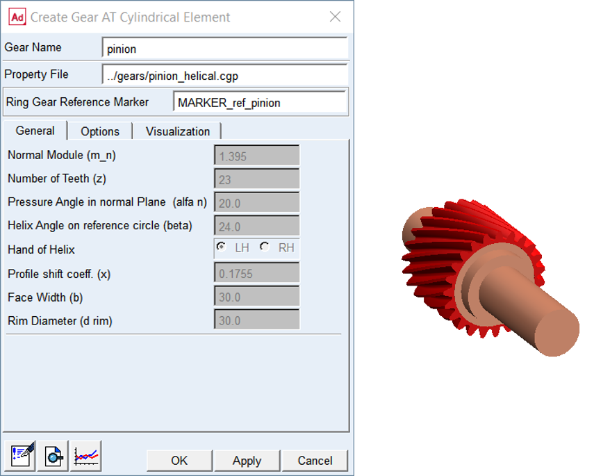
Figure 99 Create New Gear AT Element
General
The General tab of the Gear AT Element displays essential geometrical parameters of the gear (Figure 99). You cannot modify any of them here since it would redefine the gear profile. If you need to do so, follow the process described in Gear AT Advanced Shape Definition and proceed with FGear AT Mesh.
Options
The Options tab allows you to incorporate the fitting errors like Eccentricity length (fe) and Crossing Angle (f). It also allows you to activate and deactivate the Modifications and Deviations defined in respective property file of the Gear AT Element.
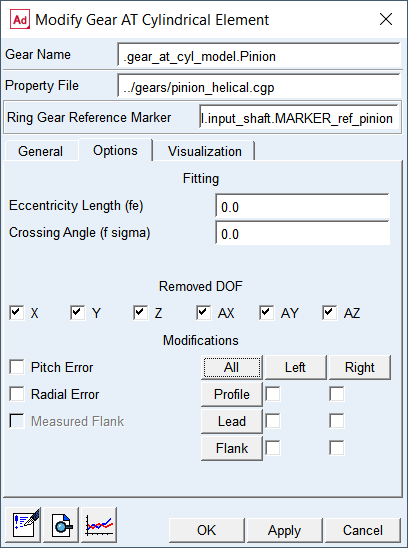
Figure 100 Gear AT Element Options
For the options | Do the following |
|---|---|
Eccentricity Length (fe) | Eccentricity is the centre offset of the gear axis from the shaft rotational axis of the Gear Element applied along X-axis of the gear reference marker (Figure 101) |
Crossing Angle (f  ) ) | Crossing angle represents angular misalignment of the Gear Element Z-axis wrt. shaft Z-axis about X-axis (Figure 101). |
Removed DOF | By default all degrees of freedom (DOF) of gear element are removed. You can release any degree of freedom, for instance AZ to mimic connection by revolute joint (see Figure 102) |
Modifications | It also allows you to activate and deactivate Modifications and Deviations defined in respective property file of Gear AT Element |
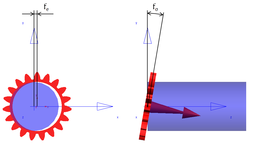
Figure 101 Eccentricity and Crossing Angle
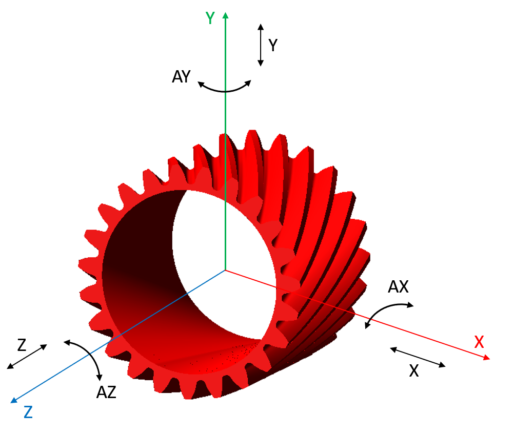
Figure 102 Removed DOF of gear element
Visualization
The visualization tab allows you to switch on/off some optional graphic features of Gear AT Element which could help you to get better understanding of results (Figure 103).
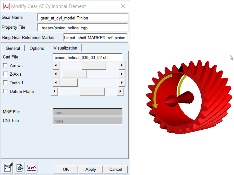
Figure 103 Gear AT Element Visualization
For the options | Do the following |
|---|---|
CAD File | Displays the name of shell graphic file of the Gear AT Element. You can toggle on/off the visualization options and also the scale of visualization can be controlled |
Arrows | Toggle on to show the rotational direction of the teeth numbering starting from the Tooth 1. You can find it helpful when inspecting results from simulation, such as maximum contact pressure over the tooth flank or so, see Figure 82. Let it not confuse you with the orientation of the gear wheel rotation. You can adjust the scale of graphics with the slider |
Z-Axis | Toggle on to show graphics of the rotational axis of the Gear AT Element. You can adjust scale of graphics with the slider |
Tooth 1 | Toggle on to show graphics of the tooth number one of the Gear AT Element displayed in black color. You can find helpful along with Arrows when inspecting results from simulation as shown on Figure 82 |
Datum Plane | When defining tooth micro geometry it is important to distinguish side tooth (left or right). Datum plane indicates the face of gear to look at when determining the side of tooth flank, see Figure 104 |
MNF File | Displays the name of Modal Neutral File in case gear wheel would be preprocessed as Full Flex Gear. It is not editable |
CNT File | Displays the name of Contact File in case the gear wheel would be preprocessed as Full Flex Gear. It is not editable |
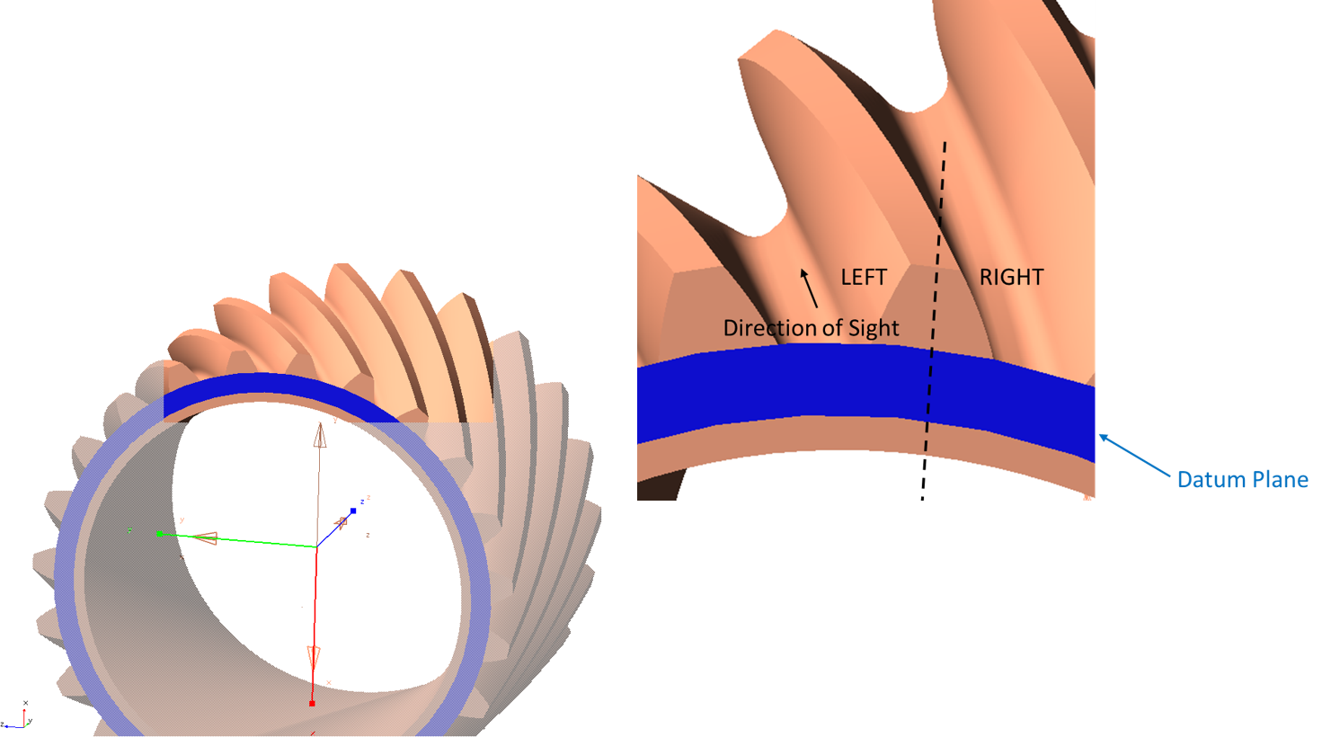
Figure 104 Datum plane