New bevel / hypoid Gear AT Element
The creation of a Gear AT Element requires the input of a name, the reference to the property file (hgp-file) and the position and orientation of the gear defined by the reference marker. The Z-axis of this marker represents the rotation axis of the gear (Figure 285).
The Gear AT Element is attached to the part belonging to the reference marker.
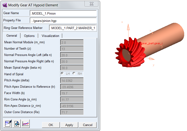
Figure 285 Create new Bevel / Hypoid Gear AT Element
General
The General tab of the Gear AT Element displays essential geometrical parameters of the gear (Figure 285). You cannot modify any of them here since it would redefine the gear profile. If you need to do so, follow the process described in Gear AT Shape Definition and proceed with Gear AT Mesh.
Options
The Options tab allows you to activate and deactivate the Modifications defined in respective property file of the Gear AT Bevel / Hypoid Element.
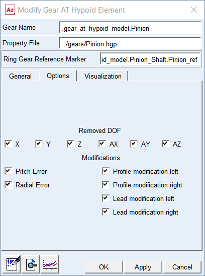
Figure 286 Bevel / Hypoid Gear AT Element Options
For the options | Do the following |
|---|---|
Removed DOF | By default all degrees of freedom (DOF) of gear element are removed. You can release any degree of freedom, for instance AZ to mimic connection by revolute joint (see Figure 287) |
Modifications | It also allows you to activate and deactivate Modifications and Deviations defined in respective property file of Gear AT Element |
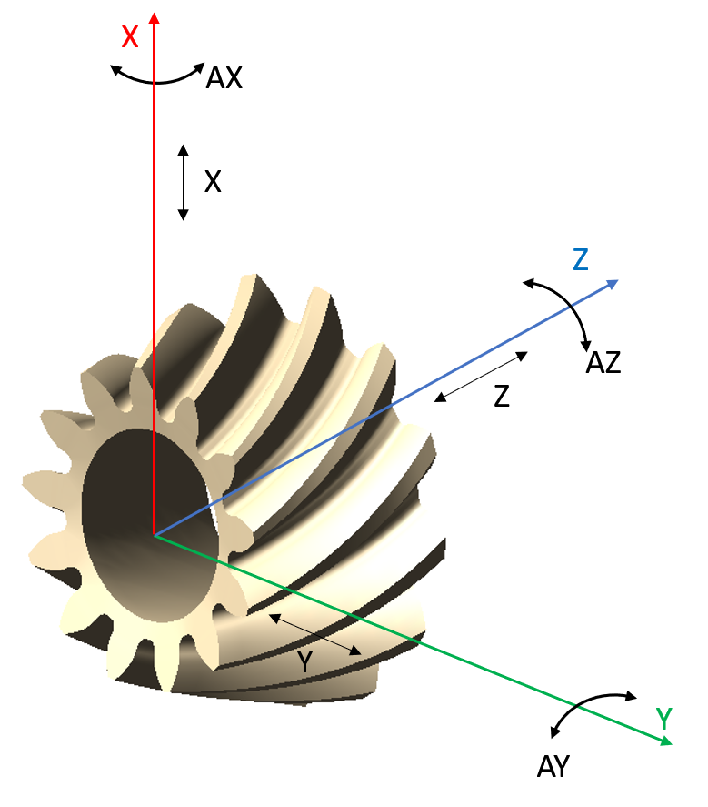
Figure 287 Removed DOF of gear element
Visualization
The visualization tab for bevel / hypoid gear element currently does not support features available for cylindrical gears.
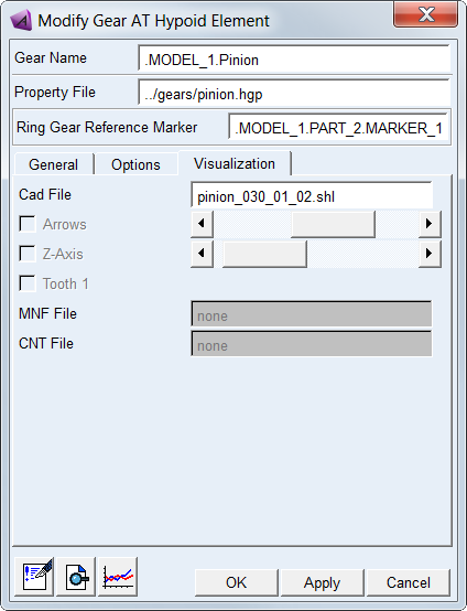
Figure 288 Bevel / Hypoid Gear AT Element Visualization
Cad File
Displays the name of shell graphic file of the Bevel / Hypoid Gear AT Element. It is not editable.
MNF File
Displays the name of Modal Neutral File in case the gear would be preprocessed as Full Flex Gear. It is not editable.
CNT File
Displays the name of Contact File in case the gear would be preprocessed as Full Flex Gear. It is not editable.