Gear AT Shape Definition
Gear AT Shape Definition allows you to create a property file (*.hgp) that defines the topology of a bevel or hypoid gear (both macro and micro geometry). In current release you can define a tooth profile by processing of CAD data only. Figure 171 shows how to access the tools you need to define your bevel or hypoid gear geometry.
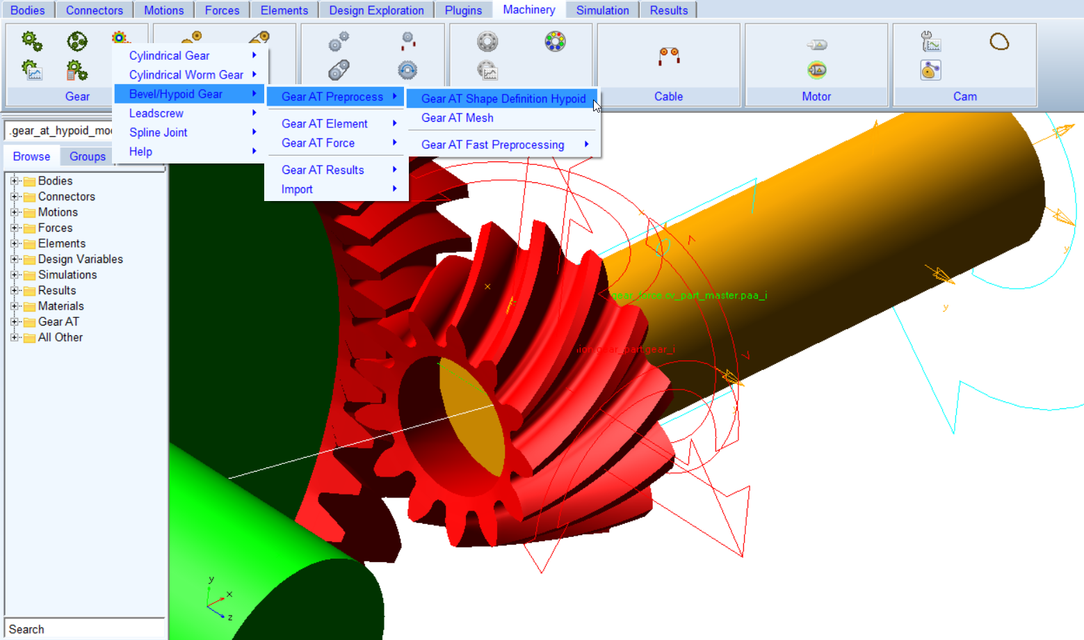
Figure 236 access to the Gear AT Shape Definition
Tooth profiles are extracted from full gear geometry defined by CAD data. The tooth boundaries and number of segments over tooth lead direction are specified in the definition file ( *.hgd).
During Bevel/Hypoid Shape Definition process an intersecting solid is created, which is substracted from CAD geometry. This will create two new solids - rim and web. The rim is used to extract the tooth profiles and the web remains stored in the working directory (*.xmt_txt) and can be further used to create the FE structure to model the full flex gear as shown on Figure 237.
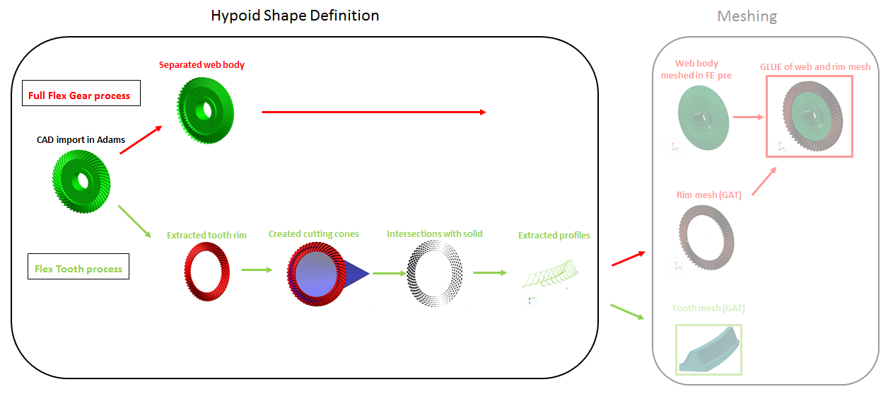
Figure 237 Bevel / Hypoid preprocessing - Shape Definition & Meshing
Depending on complexity of geometry and number of segments requested the shape definition process can take from several minutes up to 1 hour.
The Gear AT Shape Definition has following tabs to help you create a gear
The Gear AT Shape Definition has following tabs to help you edit a gear
■Mass
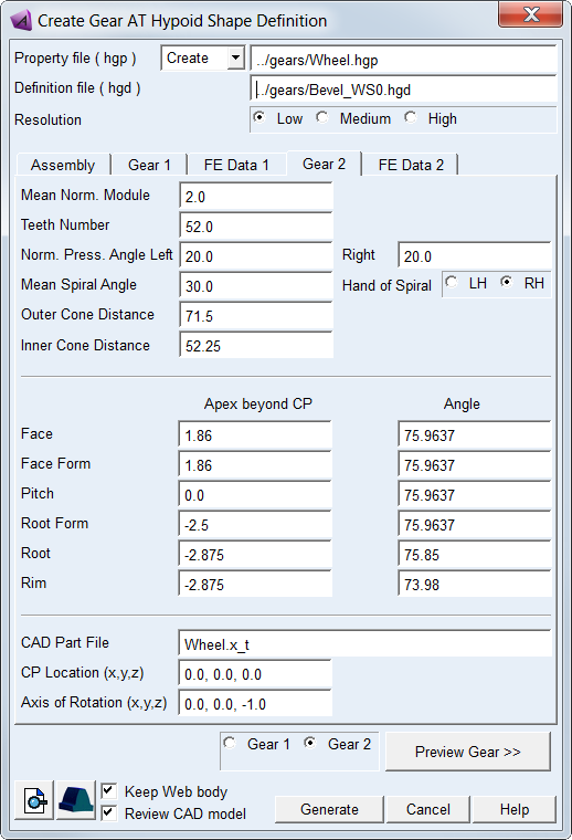
Figure 238 Bevel / Hypoid gear Shape Definition in Create mode
Main
For the options | Do the following |
|---|---|
Property file ( hgp) | In Create mode: ■Enter name of new bevel or hypoid gear property file. In Edit mode: ■Enter name of existing bevel or hypoid gear property file to edit parameters. Note: If the Property file field is empty the *.hgp file name is derived from CAD Part file name of a gear selected by the radio button. If it is not empty the field content is preserved (user name takes preference). In case one generates *.hgp file for Gear 1, proceeds with Meshing (using shortcut button in lower left corner) the Property file field is automatically cleared up . Hereafter, selecting Gear 2 for preprocessing by the radio button the Property file field is again filled in by the name derived from theCAD Part file name. |
Definition file (hgd) | Enter name of new definition file or browse for existing file (*.hgd) |
Resolution | Select resolution of imported CAD geometry to be processed for tooth profile extraction. It has influence on number of profile points extracted from CAD geometry and the time required to complete the processing. Using low resolution with gears having small curvature could results in insufficient number of profile points. Selecting higher resolution will result in more profile points extracted and longer processing time. |
Gear 1 / Gear 2 | Select a gear to process for tooth extraction to generate property file (*.hgp). |
View Property File | Displays content of property file in information window. In Create mode: ■Displays content of Definition file (*.hgd). In Edit mode: ■Displays content of Property file (*.hgp) |
Create Mesh | Opens the mesh dialog box to proceed with Gear AT Mesh pre-processing for the current bevel or hypoid gear Property file (*.hgp). |
Preview Gear >> | Opens preview in separate dialog box to visualize gear processing selected by the Gear 1 / Gear 2 radio button. It is helpful to visualize cutting cones and set up appropriate parameter values in order to extract relevant part of CAD geometry for profile extraction. |
Keep Web body | The shape definition process splits original CAD geometry in 2 parts. Selecting the toggle will save the web part in parasolid file which can be used for further FE meshing by the user and combing with toothed rim FE mesh generated by Gear AT mesher it can be used for preprocessing of the Full Flex Gear. |
Review CAD model | It keeps auxiliary Adams model in database to review result of shape definition processing. It can be useful for debugging in case of unsuccessful shape definition processing. |
Assembly
Define layout of gear pair and preview gear assembly. Besides Pitch Apex Beyond Crossing Point parameters remaining entries have no impact on the Shape Definition processing of CAD geometry of the gears. Some of the fields are not editable and are provided for information only. Meaning of parameters and convention used is depicted on Figure 240 and Figure 241.
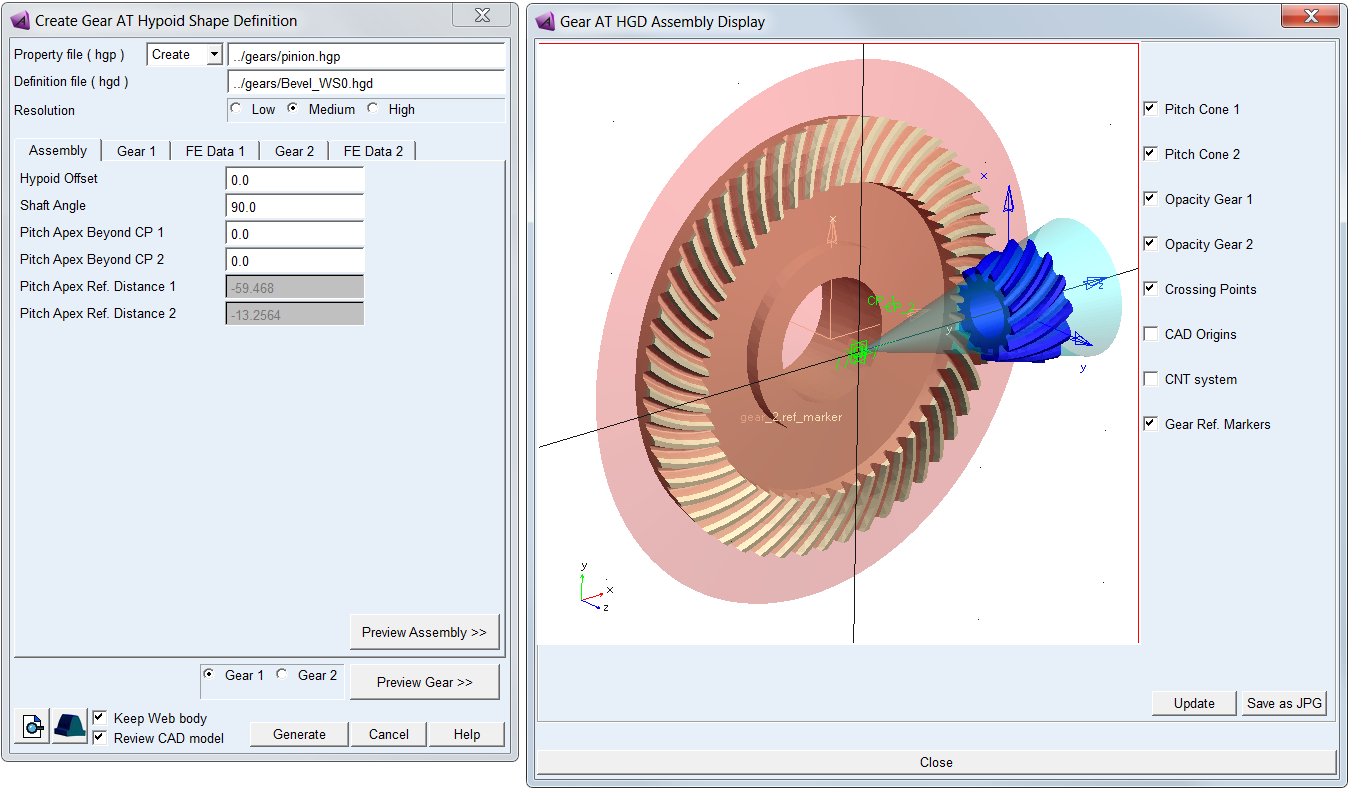
Figure 239 Assembly tab and preview of bevel / hypoid gear assembly
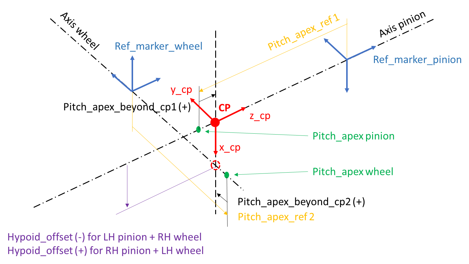
Figure 240 Bevel / Hypoid Gear pair assembly parameters
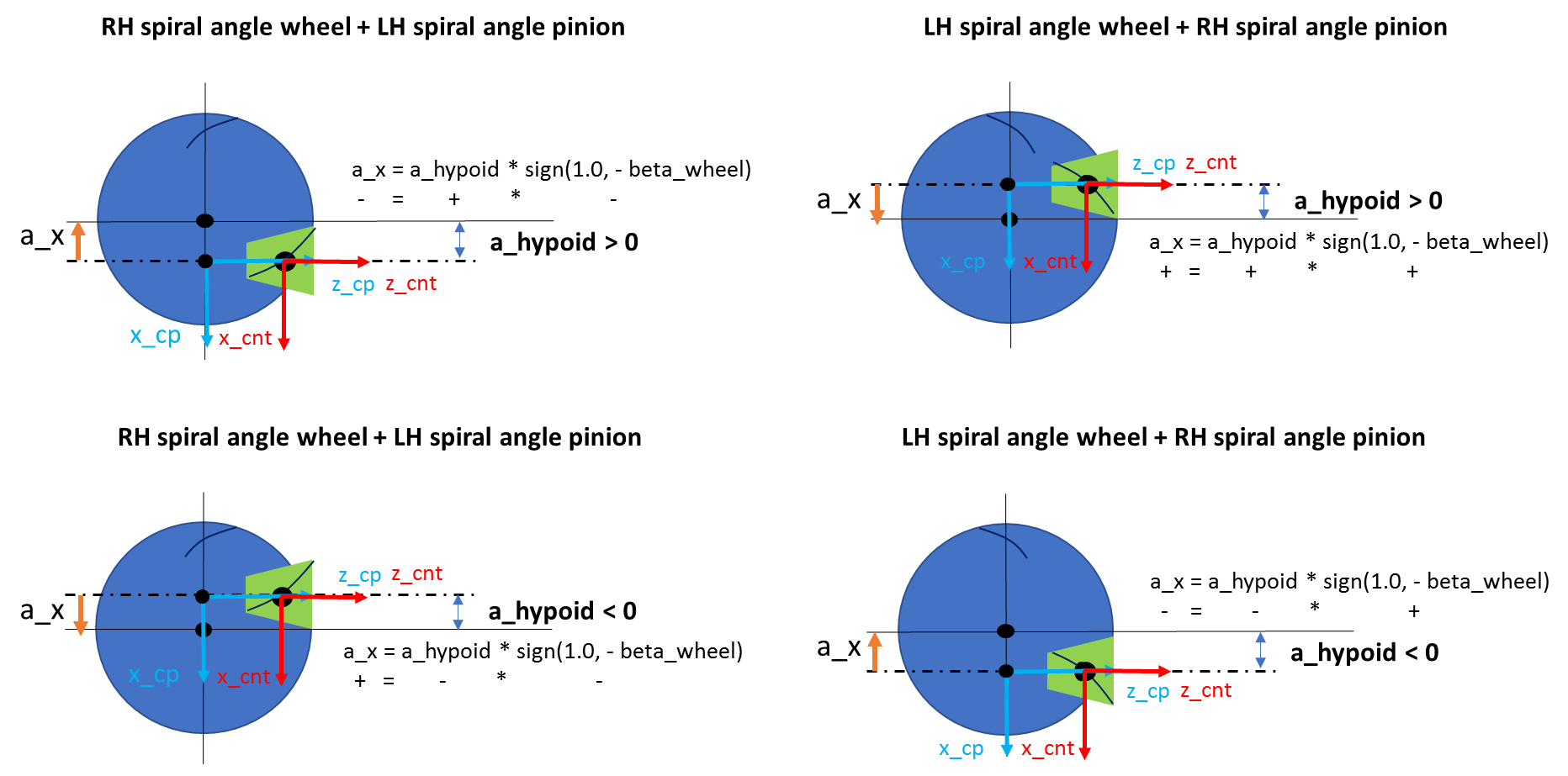
Figure 241 Spiral angle and hypoid offset convention
For the options | Do the following |
|---|---|
Hypoid Offset | Enter value of hypoid offset. It is the distance between hypoid pinion axis and the axis of hypoid gear. It is measured along the normal common to the two axes. The direction of the pinion offset depends on the sign of the hypoid offset and the hand of spiral angle - see Figure 240 and Figure 241. This parameter value is currently used for preview of assembly only. |
Shaft angle | Enter value of the angle of shaft axes. This parameter value is currently used for preview of assembly only. It is not editable and is set to default of 90 deg, however the actual model may have almost any angle. |
Pitch Apex beyond CP 1 | Enter value of pitch cone apex of Gear 1 measured from crossing point. Positive value puts cone away from the gear while negative value puts it closer (Figure 240). This field value is linked to the one in Gear 1 tab. |
Pitch Apex beyond CP 2 | Enter value of pitch cone apex of Gear 1 measured from crossing point. Positive value puts cone away from the gear while negative value puts it closer (Figure 240). This field value is linked to the one in Gear 2 tab. |
Pitch Apex Ref. Distance 1 | This field returns the value of distance of the pitch cone apex relative to the Gear 1 reference marker (Figure 240). Use this value to set up the Gear 1 reference marker in your model thus assure its correct design position. |
Pitch Apex Ref. Distance 2 | This field returns the value of distance of the pitch cone apex relative to the Gear 2 reference marker (Figure 240). Use this value to set up the Gear 2 reference marker in your model thus assure its correct design position. |
Preview Assembly | Opens preview of gears assembly in separate dialog box. It is helpful to visualize relative position of gears and its respective reference markers, crossing points , pitch cones, CAD origins and contact reference frame (CNT system) in which all gear force resulting vectors are computed. You can find it useful when defing parameters in the Gear 1 / Gear 2 tabs and when building your gear model in Adams View (Figure 239). |
Gear 1 / Gear 2
To define the gear enter basic gear tooth design information and input CAD geometry file. Most of this basic information is usually available in the form of a gear dimension sheet provided by the gear design engineer.
Note that Pitch Apex Beyond Crossing Point parameter is linked to the parameter in Assembly tab. Hand of Spiral radio button is linked between Gear 1 and Gear 2 tab and affects the direction of pinion offset (above or below centre) - see Figure 241. Dimensions entered in this tab and conventions used are explained in Figure 243.
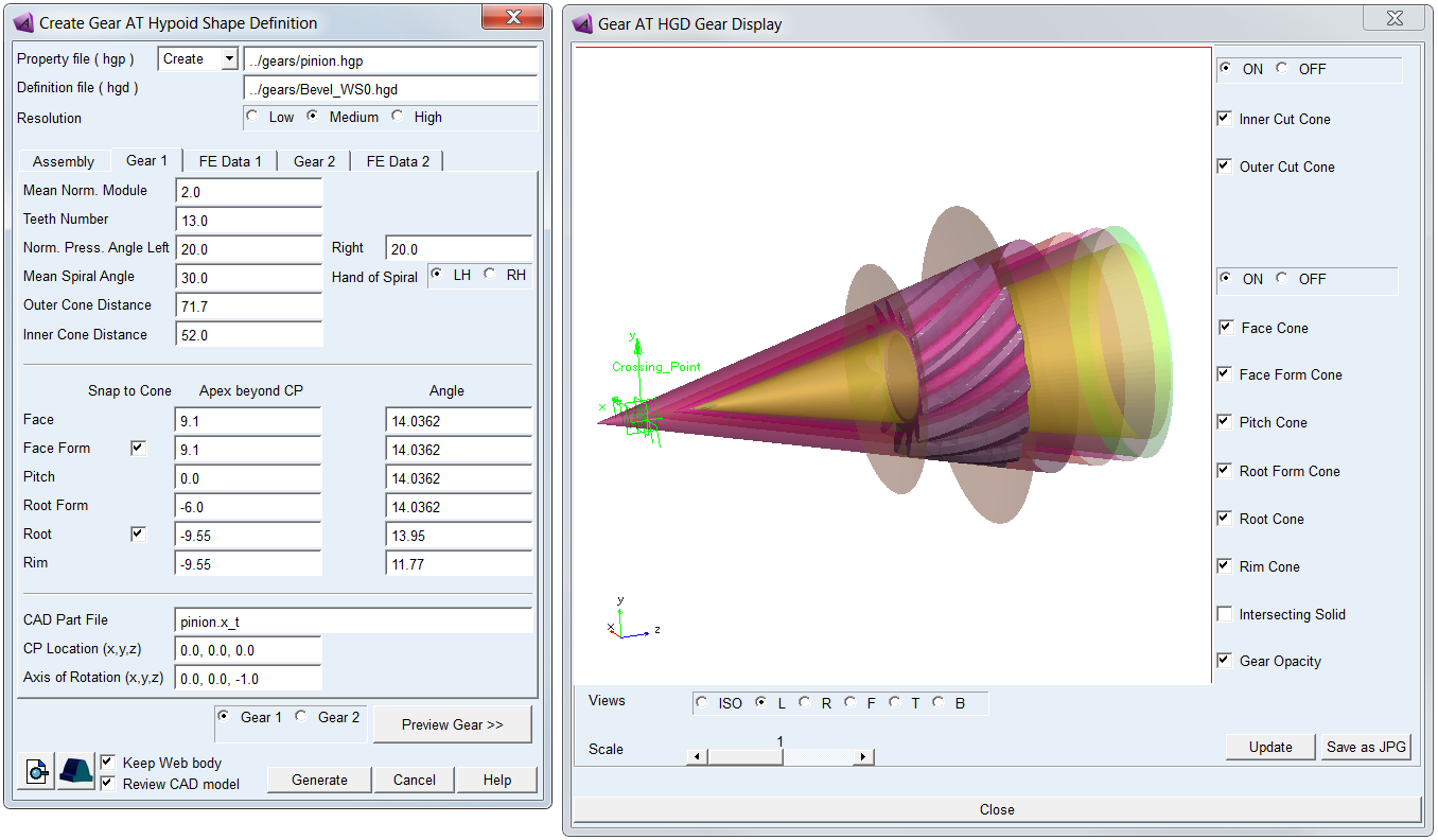
Figure 242 Gear tab and preview of bevel / hypoid gear
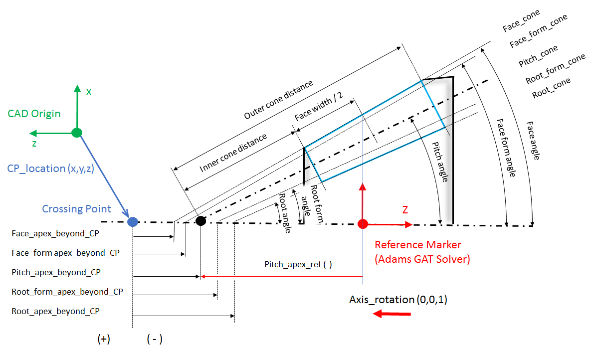
Figure 243 Definition of Bevel / Hypoid gear dimensions
For the options | Do the following |
|---|---|
Mean Norm. Module | Enter value of normal module measured in the center of the tooth face width. |
Teeth Number | Enter number of teeth. |
Norm. Press. Angle Left | Enter pressure angle of left tooth flank measured in normal plane. Convention of the tooth flank side is based on ISO standards. |
Norm. Press. Angle Right | Enter pressure angle of right tooth flank measured in normal plane. Convention of the tooth flank side is based on ISO standards. |
Mean Spiral Angle | Enter mean spiral angle of a tooth. |
Hand of Spiral | Select hand of spiral. It defines whether the spiral is left handed (negative) or right handed (positive). A left-hand gear always mates with a right-hand pinion. A right-hand gear always mates with a left-hand pinion. The “rule of thumb curvature” can be applied to either the pinion or the gear. |
Outer Cone Distance | Enter outer cone distance to locate the heel end of the teeth. It is distance measured from Pitch Apex beyond CP along pitch cone surface. It defines the last cutting cone to extract the tooth profile so it represents outer boundary of the rim portion of a gear, defining area of the tooth contact flank. |
Inner Cone Distance | Enter inner cone distance to locate the toe end of the teeth. It is distance measured from Pitch Apex beyond CP along pitch cone surface. It defines the first cutting cone to extract the tooth profile so it represents inner boundary of the rim portion of a gear, defining area of the tooth contact flank. |
Face Apex beyond CP | Enter value of cone apex measured from crossing point. |
Face Angle | Enter value of cone angle. It defines, along with Face Apex beyond CP, the upper boundary of the tooth profile. |
Face Form Apex beyond CP | Enter value of cone apex measured from crossing point. |
Face Form Angle | Enter value of cone angle. It defines, along with Face Form Apex beyond CP, the upper boundary of the tooth contact flank. If there is no tip fillet or chamfer both, the Face Form Angle and Face Form Apex beyond CP should be equal to the Face Angle and Face Apex beyond CP, respectively. |
Snap to Cone (Face Form) | Toggle ON for gears having tip radius or chamfer to put the end of the flank on the face form cone, otherwise the end of flank is detected from profile slope; here the profile quality is crucial for correct detection. face_form_tolerance = 1.0e-2 * Mean Norm. Module |
Pitch Apex beyond CP | Enter value of pitch cone apex measured from crossing point. Positive value puts pitch cone away from the gear while negative value puts it closer. Most of the gear designs use zero distance from crossing point. |
Pitch Angle | Enter value of pitch cone angle. It is measured between the gear axis and the pitch line. The sum of the pinion pitch angle and the gear pitch angle gives the Shaft Angle. The value of pitch angle is involved in most of calculations. |
Root Form Apex beyond CP | Enter value of cone apex measured from crossing point. |
Root Form Angle | Enter value of cone angle. It defines, along with Root Form Apex beyond CP, the lower boundary of the tooth contact flank. The root form cone has to be set in such a way that the root fillet area (enclosed by outer and inner cone) is beyond the cone surface. |
Root Apex beyond CP | Enter value of cone apex measured from crossing point. |
Root Angle | Enter value of cone angle. It defines, along with Root Apex beyond CP, the lower boundary of the tooth profile. |
Snap to Cone (Root) | Toggle ON to put the first profile point on the root cone if it is within a tolerance apart from this cone; measured on the section surface. Toggle OFF for gears having not conical root shape (hypoid gears or complex bevel gears). root_tolerance = 5.0e-2 * Mean Norm. Module |
Rim Apex beyond CP | Enter value of cone apex measured from crossing point. This dimension is not defined in a gear drawing. It is used with Rim Angle to define rim cone which splits a gear solid in 2 parts, a rim and web. Rim cone defines surface where FE meshes of a gear rim and gear web are glued together in the meshing pre-process step to define the Full Flex Gear. Default value is equal to the Root Apex beyond CP, which is provided upon Root Apex beyond CP field execution when Rim Apex beyond CP field is empty. |
Rim Angle | Enter value of cone angle. This dimension is not defined in a gear drawing. It is used with Rim Apex beyond CP to define rim cone which splits a gear solid in 2 parts, a rim and web. Default value is equal to the angle which gives the rim thickness of 1.0 * Mean Norm. Module. Maximum Rim Angle corresponds to: rim_thick_min = 0.35 * Mean Norm. Module Minimum Rim Angle corresponds to: rim_thick_max = 1.5 * Mean Norm. Module. Above limits are recomputed based on values entered in the Root Angle and Rim Apex beyond CP fields. The default value is provided upon Root Angle field execution when Rim Angle field is empty. |
CAD Part File | Browse for gear CAD file to be processed for tooth profile extraction. |
CP Location (x,y,z) | Enter position vector of crossing point relative to origin of CAD part. |
Axis of Rotation (x,y,z) | Enter vector to define orientation of gear part axis of rotation relative to CAD reference system. The vector should be oriented in the direction going from cone base to cone apex. |
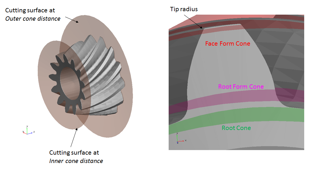
Figure 244 Preview of gear cones
Important: | Before starting the preprocessing, make sure that the intersecting solid has such a shape and dimensions that result of the boolean operation will create two separate solids. Failure to do so will result in valid *.hgp file so the Flexible Tooth modeling option is still possible but there will be no web body (*.xmt) to be used for FE meshing required for the Full Flex Gear modeling option. This situation can occur with complex gear geometry (Figure 245). |
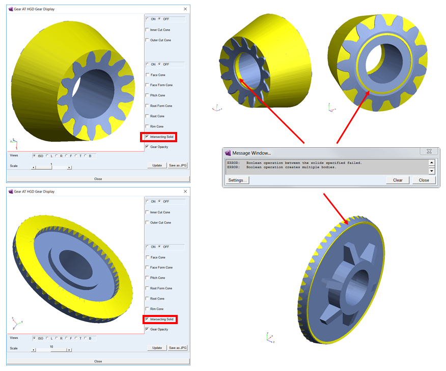
Figure 245 Preview of intersecting solid for rim extraction
FE Data 1 / FE Data 2
Specify material properties of a gear to define its stiffness and inertia properties.
Note that for Bevel / Hypoid gears the pre-processing differ in comparison to Cylindrical or Worm gears. Due to complex shape the tooth profiles are extracted during Shape Definition step what imposes fixed number of contact planes for FE Mesh preprocessing step.
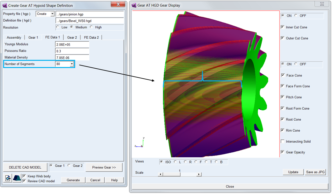
Figure 246 FE Data tab and review of CAD model after pre-processing
For the options | Do the following |
|---|---|
Young’s Modulus | The Young's modulus E is used to define Nastran MAT1 card of the flexible tooth for SOL101 and SOL103. It defines the relation between tensile strain ε and tensile stress σ by Hooke's law (Equation (6)), thus defining flexible tooth stiffness. For detailed information: see literature about theory of elasticity. |
Poisson’s Ratio | The Poisson’s Ratio is used to define Nastran MAT1 card of the flexible tooth for SOL101 and SOL103. An extension εx of a linear elastic and isotropic material is accompanied by lateral strains εy and εz. Poisson's ratio ν defines this relation by Equation (7) and Equation (8) |
Density | Enter Material density to define Nastran MAT1 card of the flexible tooth for SOL101 and SOL103. The value is also used for calculation of the gear wheel inertia properties. |
Number of Segments | Select number of segment of the gear to extract profiles between Inner and Outer Cone. The lager the Mean Spiral Angle is the higher number of segments is recommended to use. For Bevel / Hypoid Mesh the Load Element Size is fixed to 2, hence the Number of Contact Planes = Number of Segments / 2 |
General
Review basic geometrical parameters in the General tab (Figure 247). Since the tooth profiles have been extracted already and are stored in *.hgp file the values in fields are not editable.
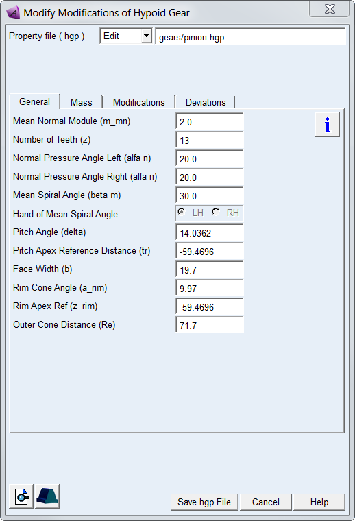
Figure 247 General tab of the Bevel / Hypoid Shape Defiition
For the options | Do the following |
|---|---|
Mean Normal Module (m_mn) | Value of module in normal plane measured in the center of the tooth face width. |
Number of Teeth (z) | Number of teeth of a gear. |
Norm. Pressure Angle Left (alfa n) | Pressure angle of left tooth flank measured in normal plane. Convention of the tooth flank side is based on ISO standards. |
Norm. Pressure Angle Right (alfa n) | Pressure angle of right tooth flank measured in normal plane. Convention of the tooth flank side is based on ISO standards. |
Mean Spiral Angle (beta_m) | Mean spiral angle of a tooth. |
Hand of Mean Spiral Angle | It defines whether the spiral is left handed (negative) or right handed (positive). |
Pitch Angle (delta) | The value of pitch cone angle is measured between the gear axis and the pitch line. |
Face Width (b) | The length of tooth flank in lead direction |
Rim Cone Angle (a_rim) | The rim cone defines the boundary of the gear rim to the finite element model of the wheel body. |
Rim Apex Ref (z_rim) | It defines the value of distance of the pitch cone apex relative to the gear reference marker (Figure 240). Use this value to set up the gear reference marker in your model thus assure its correct design position. |
Outer Cone Distance (Re) | Outer cone distance dimension locates the heel end of the teeth. It is distance measured from pitch cone apex along pitch cone surface. It defines the last cutting cone to extract the tooth profile so it represents outer boundary of the rim portion of a gear, defining area of the tooth contact flank. |
Mass
The Mass card of the Shape Definition process allows you to define the mass of the gear based either on the Geometry and Material Type or by specific User Input (Figure 205). In the former case the mass, center of mass and inertia tensor is computed later on by the mesher based on FE mesh volume. In the latter case enter all required data in current model units. In either case, inertia data are written to the *.hgp file.
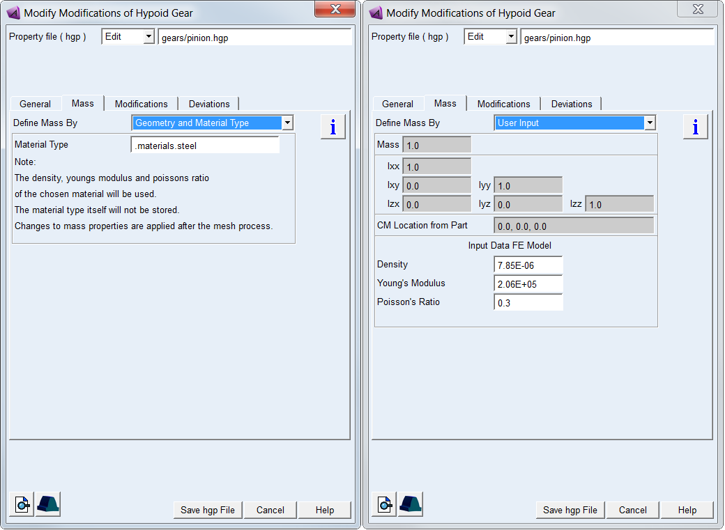
Figure 248 Bevel / Hypoid gear mass and material properties
For the options | Do the following | |
|---|---|---|
Define Mass By | Set to: ■Geometry and Material Type ■User Input | |
For the option Define Mass By the Geometry and Material Type : | ||
Material Type | Choose material type either from predefined material library - right click the field and go to Material - Browse, or create a new one. Note that material of steel is set by default. | |
For the option Define Mass By the User Input: enter value of Mass, the principal mass moments of inertia (Ixx, Iyy, Izz) and cross-products of inertia (Ixy, Izx and Iyz). Note that you still need to define material parameters to define FE model of flexible tooth properly | ||
Mass | Enter the mass of the part. | |
Moments of inertia | Enter the mass moments of inertia. | |
CM Location from Part | Enter location vector of center of mass expressed in local part reference frame. | |
Density | Enter Material density to define Nastran MAT1 card of the flexible tooth for SOL101 and SOL103. The value is also used for calculation of the gear wheel inertia properties. | |
Young’s Modulus | The Young's modulus E is used to define Nastran MAT1 card of the flexible tooth for SOL101 and SOL103. It defines the relation between tensile strain ε and tensile stress σ by Hooke's law (Equation (6)), thus defining flexible tooth stiffness. For detailed information: see literature about theory of elasticity. | |
Poisson’s Ratio | The Poisson’s Ratio is used to define Nastran MAT1 card of the flexible tooth for SOL101 and SOL103. An extension εx of a linear elastic and isotropic material is accompanied by lateral strains εy and εz. Poisson's ratio ν defines this relation by Equation (7) and Equation (8) | |
Modifications
Gear tooth flank modifications are applied to compensate for manufacturing errors, deformation of the teeth due to load and also for shafts and gear housing deformation thus ensure a proper meshing to achieve more favorable load distribution and reduced transmission error. The ultimate goal is to reduce gear wear and vibrations induced by the gear pair operation, thus help to design durable gearbox fulfilling specified NVH parameters.
All types of tooth flank modification can be defined separately for left and right flank or symmetrically on both flanks. The convention for tooth flank side used throughout the Gear AT is based on ISO standards.
Important: | Values of gear modifications are usually defined in units of micrometers in gear specification sheets or drawings. However, values of all parameters have be entered in model units! |
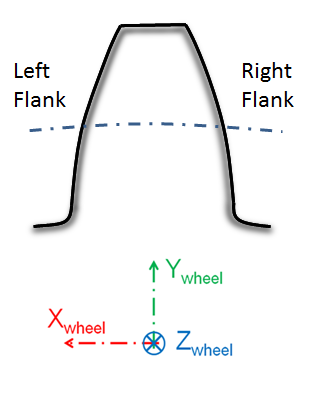
Figure 249 Definition of left and right flank
Gear AT supports following gear profile and lead modifications which are all superimposed over the tooth flank:
Profile Modifications
Profile modifications are mostly used to decrease the engagement shock and the involved strain and noise. Types of profile modifications for bevel / hypoid gear supported by Gear AT include barreling (vertical crowning), eccentricity, symmetry, involute slope correction and twist. The modifications can be set individually for left and right tooth flank or symmetrically on both flanks. The layout for profile modification parameters is depicted in Figure 207
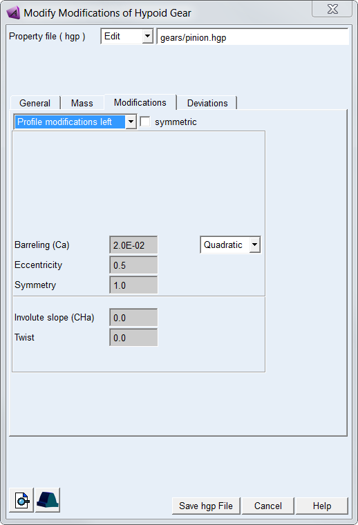
Figure 250 Bevel / Hypoid profile modification tab
For the options | Do the following |
|---|---|
Profile modifications option menu | Select tooth flank side to apply profile modifications: ■Profile modifications left ■Profile modifications right |
symmetric | Toggle ON to apply the same profile modifications on both flanks. |
Order of modification ( Barreling) | Select order of polynomial of modification: ■None – no modification is applied ■Linear ■Quadratic ■Cubic ■Custom - select to enter all 3 polynomial coefficients to define total value of modification |
Barreling (Ca) | Enter value of barreling at root form and face form cone (tip) - see Figure 251 |
Eccentricity | Barreling eccentricity controls position of modification centre (Figure 251): ■eccentricity = 0.0 - centre at face form cone ■eccentricity = 0.5 - centre in the middle of root form and face form cone ■eccentricity = 1.0 - centre at root form cone |
Symmetry | Barreling symmetry defines amount of modification at root Caf as factor of modification at tip Caa (Figure 251): ■barreling at tip - Caa = Ca ■barreling at root - Caf = Caa * symmetry |
Involute slope (CHa) | Enter value of involute slope modification. The positive correction removes material on tip while negative correction removes material on root - see Figure 252 |
Twist | Enter value of twist modification - see Figure 253 and Figure 254. |
Barreling
Barreling (profile crowning) is a convex shape added to the involute curve to prevent hard contact near the tip and root. Barreling  is defined as a polynomial function of the dimensionless involute curve parameter u. Eccentric barreling can be used to apply different relief at root and tip form cone. Eccentricity factor corresponds to ratio of diameters rather than length of contact path.
is defined as a polynomial function of the dimensionless involute curve parameter u. Eccentric barreling can be used to apply different relief at root and tip form cone. Eccentricity factor corresponds to ratio of diameters rather than length of contact path.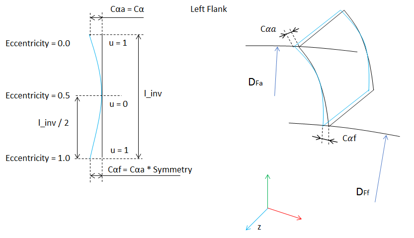
Figure 251 Bevel / Hypoid barreling modification
Involute Slope
Involute slope is used to compensate for tooth deflection differences between the two meshing gears and to compensate for system deflections that would otherwise result in hard contact near the root or the tip of one of the gears. It defines correction in pressure angle relative to root form cone. The positive correction removes material on tip as shown by Figure 252 for the left flank, while negative correction removes material on root.
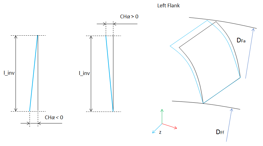
Figure 252 Bevel / Hypoid involute slope
Twist
Twist modification is a flank surface torsion along the lead line which is ;ocated in the middle of profile, see Figure 253. The twist is applied in correlation with involute slope, but always with opposite sign on tooth sides. The positive value  means linear increase of torsion angle from negative side to positive side of flank, see Figure 253 and Figure 254.
means linear increase of torsion angle from negative side to positive side of flank, see Figure 253 and Figure 254.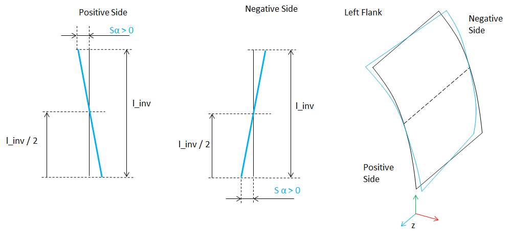
Figure 253 Positive Twist Modification for Left Flank
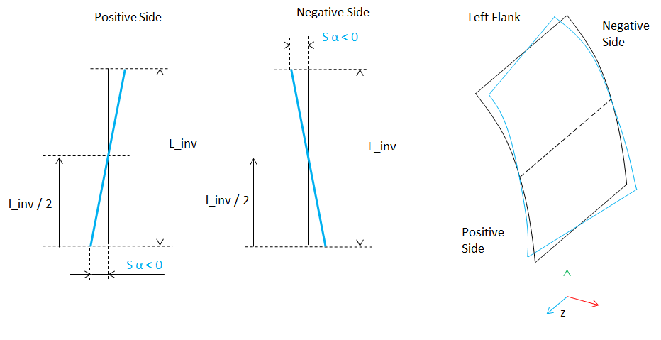
Figure 254 Negative Twist Modification for Left Flank
Lead Modifications
Lead modifications are used to attain a low displacement sensitivity and to avoid strain peaks occurring due to displaced positions of the gear axis or spiral deviations of the flank. Types of lead modifications for bevel and hypoid gears supported by Gear AT include crowning and lead slope changes. The Figure 255 shows lead modifications card layout for the left flank.
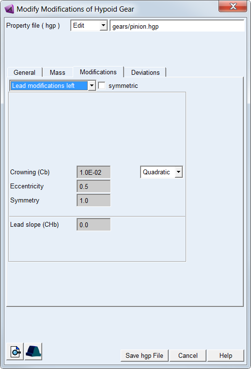
Figure 255 Lead Modification Card
For the options | Do the following |
|---|---|
Lead modifications option menu | Select tooth flank side to apply lead modifications: ■Lead modifications left ■Lead modifications right |
symmetric | Toggle ON to apply the same lead modifications on both flanks. |
Order of modification (Crowning) | Select order of polynomial of modification: ■None – no modification is applied ■Linear ■Quadratic ■Cubic ■Custom - select to enter all 3 polynomial coefficients to define total value of modification |
Crowning (Cb) | Enter value of crowning at the edges of a flank - see Figure 256 |
Eccentricity | Crowning eccentricity controls position of modification centre (Figure 256): ■eccentricity = 0.0 - centre at inner cone ■eccentricity = 0.5 - centre in the middle of inner and outer cone ■eccentricity = 1.0 - centre at outer cone |
Symmetry | Crowning symmetry defines amount of modification at the edge of outer cone CbII as factor of modification at inner cone CbI (Figure 256): ■crowning at inner cone - CbI = Cb ■crowning at root - CbII = CbI * symmetry |
Lead slope (CHb) | Enter value of lead slope modification. The positive correction removes material on outer cone while negative correction removes material on inner cone - see Figure 257 |
Crowning
Crowning is convex shape along the width of a tooth. It is used to maintain contact in the central region of the tooth flank width allowing for gear angular and axial misalignment. This type of tooth modification is preferably used on narrow gears. The amount of crowning should not be larger than necessary as otherwise it would reduce area of contact, thus lowering load capacity of a gear pair.
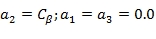
Crowning is applied in a perpendicular plane to the contour of the tooth. Crowning  is defined as a polynomial function of a dimensionless parameter u (Figure 256). The distribution of the crowning across the flank width can be linear, quadratic, cubic or custom. The custom option allows direct definition of crowning function coefficients, thus allow the combination of distribution types previously mentioned, say linear with quadratic distribution.
is defined as a polynomial function of a dimensionless parameter u (Figure 256). The distribution of the crowning across the flank width can be linear, quadratic, cubic or custom. The custom option allows direct definition of crowning function coefficients, thus allow the combination of distribution types previously mentioned, say linear with quadratic distribution.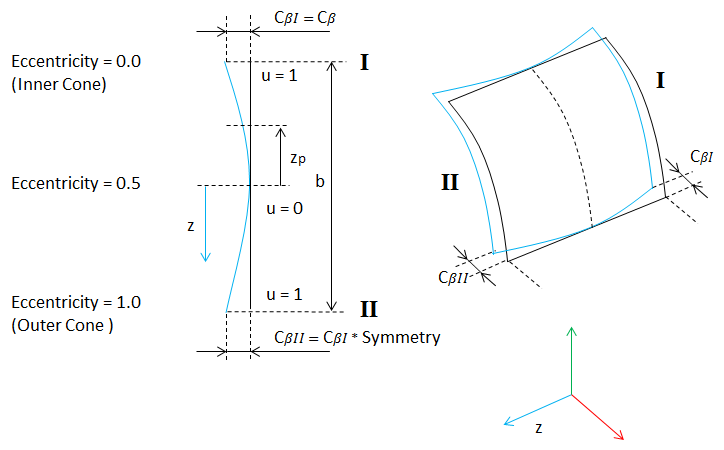
Figure 256 Definition of Crowning for Left Flank
The dimensionless parameter u follows from Equation (24), the polynomial function is given in the Equation (25):
 | (24) |
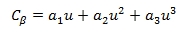 | (25) |
The Equation (26) gives the relation between the crowning drop  and crowning radius R. In general,
  is very small compared to the width of the tooth; so Equation (27) should be a valid approximation for a circular crowning:
and crowning radius R. In general, is very small compared to the width of the tooth; so Equation (27) should be a valid approximation for a circular crowning: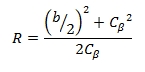 | (26) |
 | (27) |
Lead Slope
Lead Slope defines correction of the helix angle (Figure 257), which is used to improve contact with mating gear teeth when system deflections would otherwise cause edge loading.
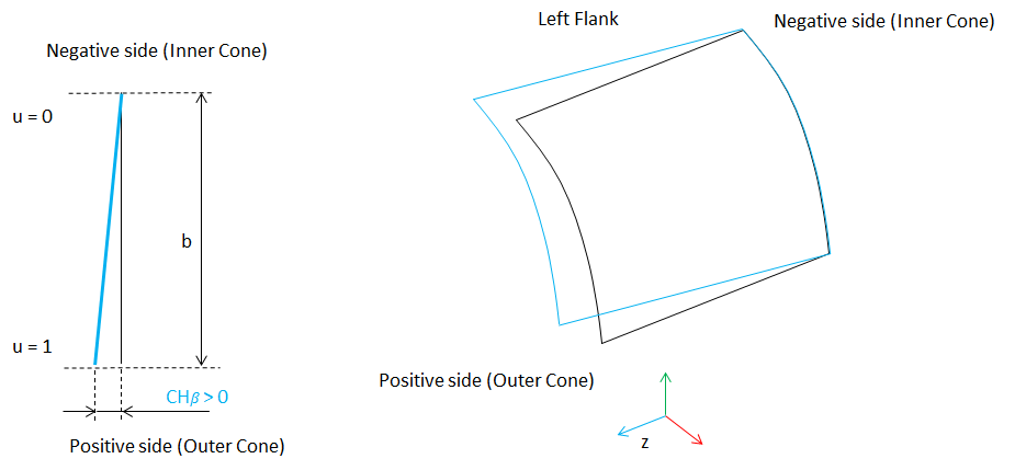
Figure 257 Positive Lead Slope
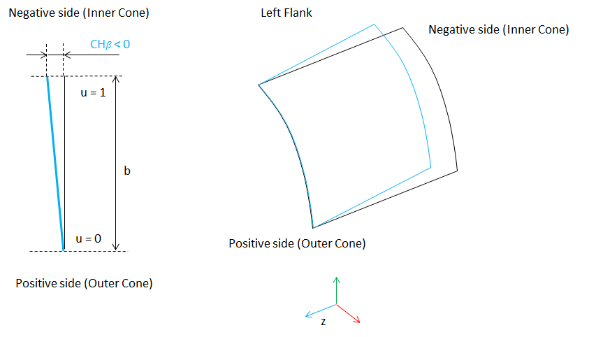
Figure 258 Negative Lead Slope
The positive sign of the lead slope modification yields the same sense of spiral angle change for both, left and right flank. The positive correction is depicted on Figure 257, while the negative is on Figure 258.
Deviations
You can define bevel / hypoid gear manufacturing errors to be taken into account in the contact simulation. Enter Radius Error for every tooth to describe deviations from ideal pitch circle and enter Pitch Error for every tooth to describe deviations from angular pitch, see Figure 259.You can also enter amplitude and phase shift to generate harmonic distribution of error by cosine function or apply generator of random numbers to get random distribution from interval of <-amplitude , + amplitude>. Positive value of Radius Error results in larger tooth radius and positive Pitch Error rotates tooth in counter clock-wise direction according to the right hand rule.
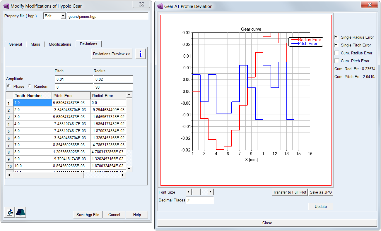
Figure 259 Bevel / Hypoid gear deviations tab
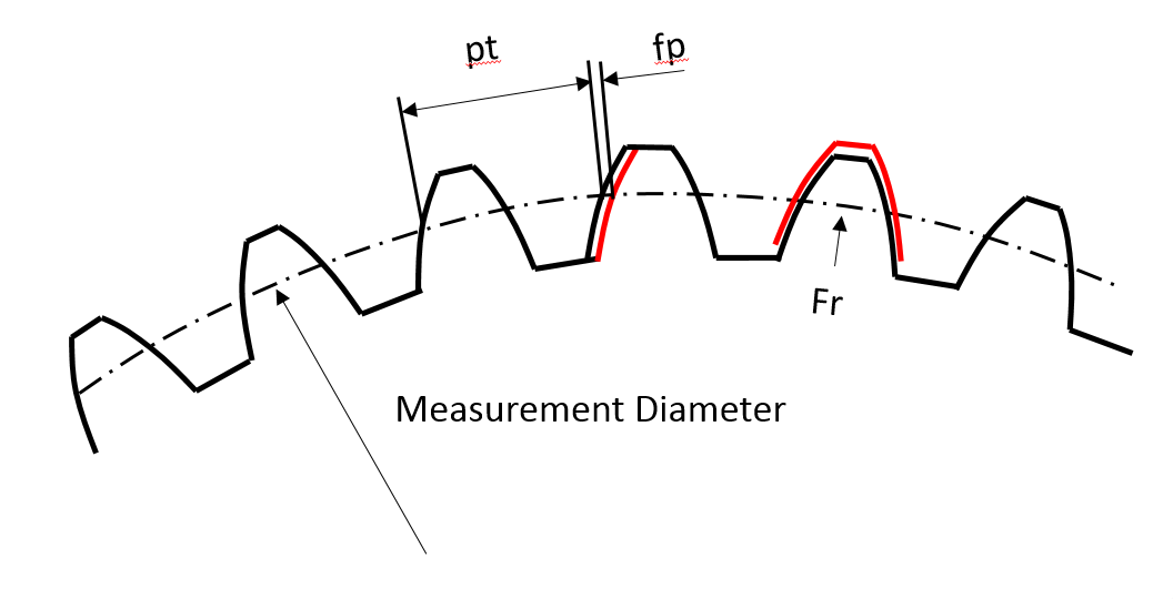
Figure 260 Radial and pitch deviations of bevel / hypoid gear tooth