New Gear AT Nut / Spindle Element
The creation of a Gear AT Nut Element requires the input of a name, the reference to the property file (TLP-file) and the position and orientation of the nut defined by the reference marker. The Z-axis of this marker represents the rotation axis of the nut(Figure 341).
The Gear AT Element is attached to the part belonging to the reference marker.
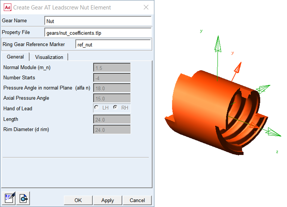
Figure 341 Create new Gear AT Nut Element
General
The General tab of the Gear AT Element displays essential geometrical parameters of the gear (Figure 341). You cannot modify any of them here since it would redefine the gear profile. If you need to do so, follow the process described in Gear AT Shape Definition and proceed with Gear AT Mesh.
Visualization
The visualization tab for nut element currently does not support features available for spindle nut gears.
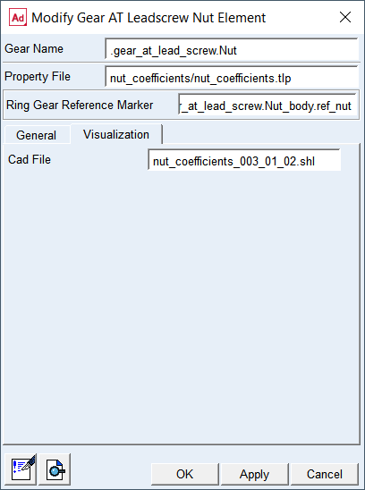
Figure 342 Gear AT Nut Visualization tab
Cad File
Displays the name of shell graphic file of the Gear AT Nut Element. It is not editable.