Gear AT Mesh
Once the gear data are defined in the *.TLP property file you are ready to preprocess gear tooth FE model to get starts flank contact surfaces and stiffness matrix for Gear AT contact simulation. The Figure 332 shows how to access Gear AT Mesher interface to preprocess your gear before you could define Gear AT Element in Adams model. The data flow involved in the mesh is depicted on Figure 326.
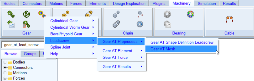
Figure 325 Launch of Gear AT Mesh
FE preprocessing starts by launching Gear AT mesher (orange color; see Figure 326) with input data from *.TLP file prepared in the Gear AT Shape Definition step and *.opt file which consists of data you input in the FE Data tab of the mesher dialog box. Output of the mesher is Adams geometry *.shl file, flank contact surface for rigid contact modeling in *.TLS file and updated *.TLP file by inertia data of the gear. In order to include gear tooth flexibility in contact simulation, Nastran SOL 101 needs to be executed (green color). The Gear AT op2_reader extends the content of *.TLS file with results from Nastran run.
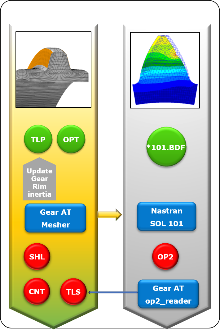
Figure 326 Data flow of Gear AT Mesh
The tab options of Create Gear AT Mesh dialog box are
Main
For the options | Do the following |
|---|---|
Property file | Browse for existing gear property file to preprocess FE mesh model |
Mode | Select one from available gear modeling options: ■Rigid Gear ■Flex Tooth |
Import *.opt | The parameters for the meshing are stored in a file with the extension *.opt. if this file exist, you can retrieve this data through the Import *.opt button. |
Preprocessor | Choose one from following options: ■Internal ViewFlex: use this option when there is no Nastran installation available and you don’t wont to draw additional Adams View license to execute the ViewFlex. Please note that additional ViewFlex license is required ■External ViewFlex: use this option when there is no Nastran installation available. On background there is SOL103 running by Adams embedded Nastran Solver. This option allows you to continue working since ViewFlex is executed in external shell window hence the main window remains active. Please note that additional Adams View and ViewFlex license is required. This option is not available on linux ■Internal Nastran: use this option when you have Nastran installation available. It makes use of Nastran SMP license if available ■External Nastran: use this option when you have Nastran installation available. It makes use of Nastran SMP license if available. This option allows you to continue working since standalone Nastran is executed in external shell window hence the main window remains active. Please note that additional Nastran license is required. This option is not available on linux ■Mesher Only: use this option to verify that FE Mesh is valid before running SOL101 and SOL103 or you need to run Nastran on different computer ■Mode Extraction Only (Full Flex Gear mode): use this option when you have run Nastran outside of Gear AT. Before execution make sure you provide Nastran OP2 result file from SOL103 in the directory where gear Property File is located ■OP2 Reader Only (Flex Tooth mode): use this option when you have run Nastran outside of Gear AT. Before execution make sure you provide Nastran OP2 result file from SOL101 in the directory where gear Property File is located |
General
The general tab (Figure 327) displays some parameters of the spindle nut gear, which are stored in the *.TLP file. However, none of them are editable as the tooth profile was defined in the Gear AT Shape Definition step already.
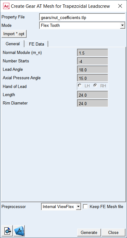
Figure 327 Gear AT mesh dialog box - General tab
FE Data
You can control FE mesh resolution as well as contact mesh resolution of flexible tooth FE model and resolution of Adams shell graphics thus performance of the model.
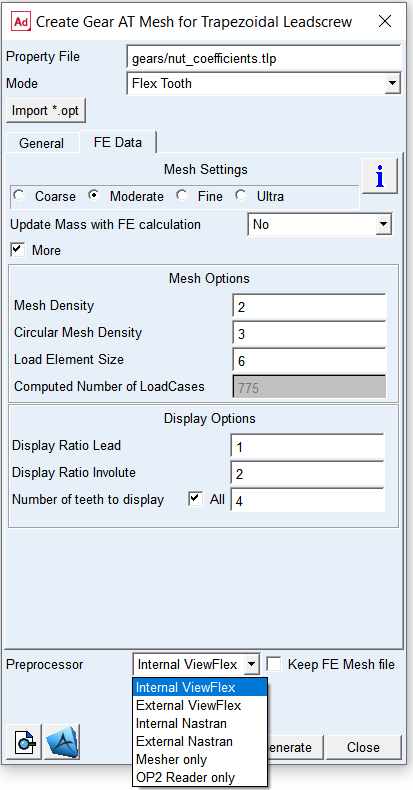
Figure 328 Gear AT mesh dialog box - Flex Tooth FE data tab
For the options | Do the following |
|---|---|
Mesh Settings | Choose one of the following options to define FE Mesh resolution (see Figure 329 and Figure 331): ■Coarse - Mesh Density = 3 ■Moderate - Mesh Density = 4 ■Fine - Mesh Density = 5 ■Ultra - Mesh Density = 6 Default option: Moderate |
Update Mass with FE calculation | Choose one of the options Yes or No. In case you select Yes the Gear AT Element mass properties will computed by the Gear AT Mesher and updated in the TLP file. NOTE: For Rigid Gear and Flex Tooth the mass properties correspond to the gear ring only. Default: No |
If selected More option: | |
Mesh density | For Flex Tooth option: Enter value from 2 to 4 representing 16, 24 or 32 elements along the straight edge of trapezoid profile; see Figure 329 Default: 2 |
If selected Flex Tooth option: | |
Circular mesh density | Enter values between 3 to 6 representing 32, 40, 48, 56 sections resp. contact planes along circumference of spindle, see Figure 331 Default: 3 |
Load Element Size | Define the number of finite elements per section in circumferential direction. Enter value from 1 to 6 (2 means there are 2 elements between the contact planes); see Figure 332 |
Approximate Number of LoadCases | This value indicates approximate number of static load cases to be applied on contact surfaces to define Flex Tooth stiffness matrix. It is computed based on the mesh settings above to inform user about size of FE model |
Display Ratio Circular | Enter a value between 1 and 4 to define resolution of a gear shell graphics along circumferential direction. 1 means finest, 4 means coarsest resolution; see Figure 333. A coarse resolution can result in tessellated display of tooth geometry. Default: 2 |
Display Ratio Height | Enter the value between 1 and 5 to define resolution of a gear shell graphics along straight part of trapezoidal profile. 1 means finest, 5 means coarsest resolution for the shell graphics); see Figure 333 |
Number of Starts to display | Enter a number of starts to be created for a gear shell geometry. For full screw toggle All teeth of a screw. In case of segment screw enter required number of starts |
The parameters for the meshing are stored in a file with the extension *.opt. If this file exists, you can retrieve this data through the Import *.opt toggle.
Extended definition:
Update mass with FE calculation
Make your choice about Update mass with FE calculation option. In case you select Yes the Gear AT Element mass properties will correspond to the gear ring only, what is effectively the mass of solid represented by the shell graphics. It is assumed you will define the mass properties of the gear wheel body by the shaft part to which you attach the Gear AT Element. In case you defined mass by User Input in Mass tab of the Gear AT Shape Definition dialog box you should opt for No to not Update mass with FE calculation, hence the Gear AT Element you will define later on will represent mass properties of the gear ring and gear wheel body.
Mesh settings
Choose from Coarse, Moderate, Fine, and Ultra options, which are predefined options to control FE mesh and load mesh division over the tooth flank. You can switch on the toggle More to manually enter all input parameters.
Mesh Density
It defines the number of finite elements along the straight line of tooth profile; see Figure 329. Valid input entries for mesh density are 2 to 4, representing 16, 24,32 elements along the straight line of tooth profile.
This input parameter allows you to select the preference with respect to accuracy versus CPU-time. A low value for mesh density will result in a coarser Nastran model, what gives generally a short CPU-time. One has to keep in mind, that a coarse model is generally slightly stiffer.
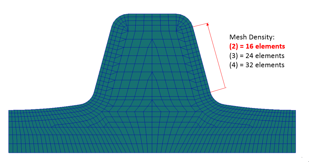
Figure 329 Mesh density leadscrew
Circular mesh density
It defines the number of equidistant divisions or sections for screw thread per one lead, resp. for 360 degree turn around the screw axis; see Figure 331. It is suggested that one can use a similar settings for the mating screw and nut defined in Gear AT Force. The section is representing one contact plane.
Contact between screws is checked at each contact plane of nut of the Gear AT Force. Having too small number of contact planes may lead to some numerical noise. The amount of CPU time increases with increasing number of contact planes. You need verify the appropriateness of your selection.
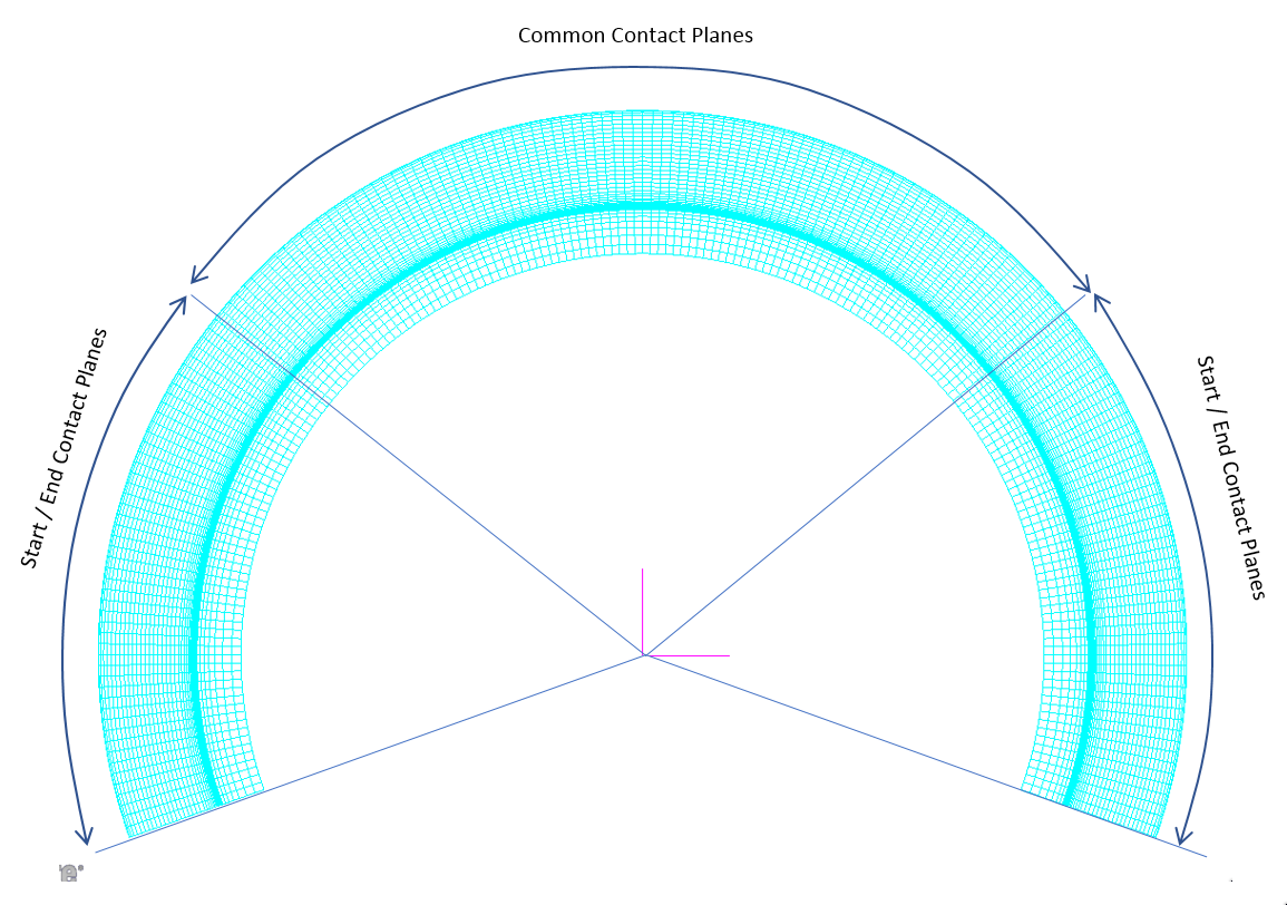
Figure 330 FEM model of thread
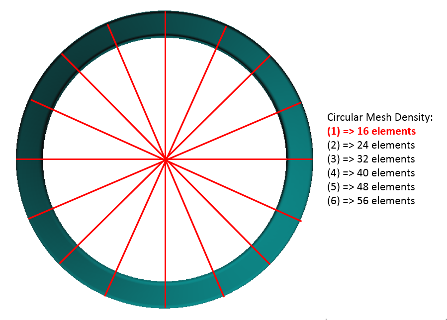
Figure 331 Circular mesh density
The FE Model for leadscrew is not generated for the full length of the screw as most of the sections have identical properties. The only exceptions is at the beginning resp. end of the thread where the tooth profile end in different designs. To decrease the CPU time for pre-processing the FE model consist from 3 main sections. The middle part represents the common properties of the screw except the beginning and end portions, here are symmetrically to the vertical axis 7 contact planes to capture the stiffness. On each sides the common sections continues with transient contact planes representing the stiffness properties on beginning and end of the screw thread, see Figure 330.
Load Element Size
It defines the number of finite elements in circumferential direction per section (between adjacent contact planes); see Figure 332. You can select a value between 1 and 6, where 6 means 6 elements between the contact planes.
A larger number of this input will increase the size of the FE-mesh and hence the CPU-time of the Nastran analysis. However, it does not influence the value of Computed Number of LoadCases.
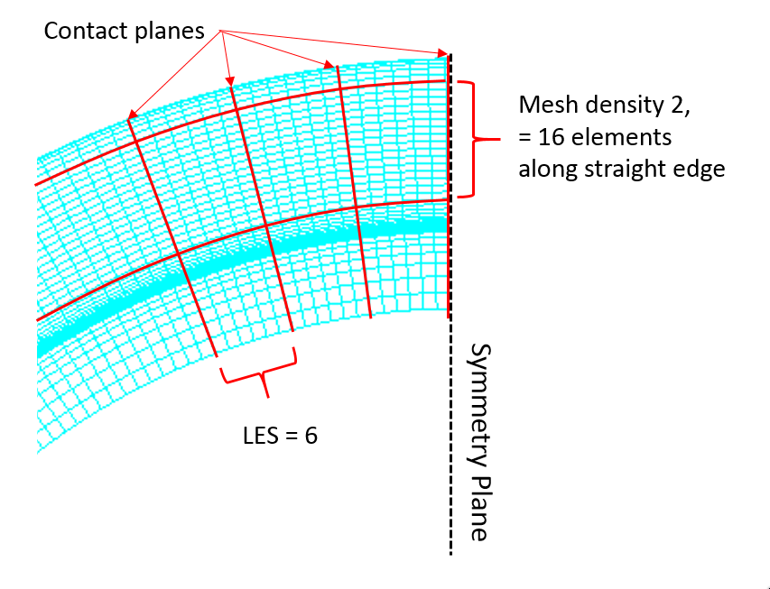
Figure 332 Load element size
Computed Number of Load Cases
This field returns approximate number of load cases that are calculated in the Nastran Solution 101 what is proportional to the rank of tooth stiffness matrix.
Display Ratio Circular
It controls resolution of geometrical representation in Adams View. It defines the aspect ratio of the shell elements along the circumference of shell geometry. The input value of 1 means finest and 4 the coarsest resolution for the shell graphics.
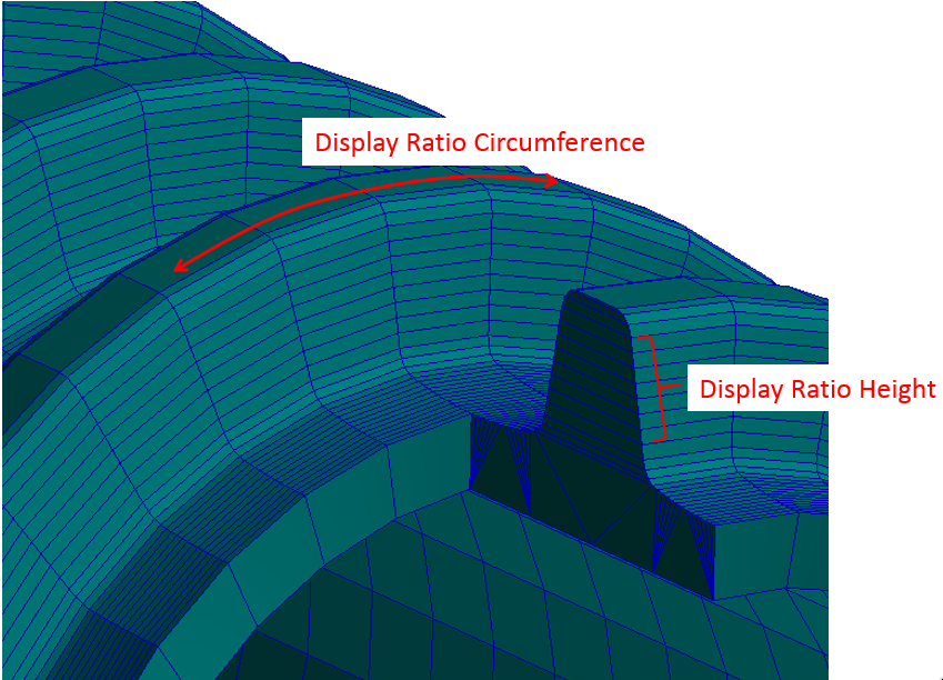
Figure 333 Display ratio lead and height
Display Ratio Height
It controls resolution of geometrical representation in Adams View. It defines the number of FE elements per one shell geometry element along straight line direction. The input value of 1 means finest and 5 for coarsest resolution for the shell graphics.
The Gear AT Mesh will be started and you will see the echo of the input data (contents of the *.opt file and *.TLP file) and the start of the actual meshing as shown in Figure 334. The option 'quiet' suppresses the output to the screen. The *.TLS file contains all information about the geometry of the tooth. If a flexible tooth has been requested, the *.TLS file will be expanded by the op2-reader with results from Nastran.
The file name of the *.TLS file and bulk date file of the gear tooth is composed as *_xxx_yy_zz.wgs and *_xxx_yy_zz.dat where:
■xxx circular mesh density
■yy mesh density
■zz load element size
The filename of the *.shl file is composed as *_xxx_yy_zz.shl where:
■xxx number of contact planes
■yy display ratio circular
■zz l display ratio height
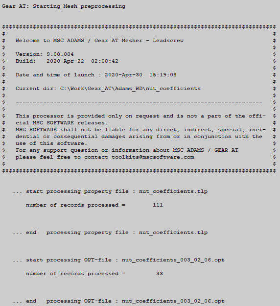
Figure 334 Start of Gear AT Mesh
Gear AT mesh also reports the results of the curve-fitting as shown in Figure 335; 'difference' shows the distance between the input point and its curve-fitted location. These values should be generally very small. Figure 336 shows the successful termination of the Gear AT Mesh.
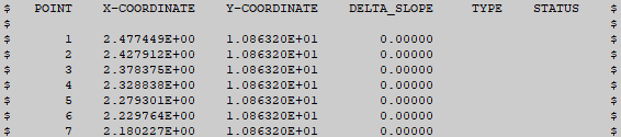
Figure 335 Results of curve-fitting
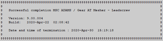
Figure 336 Termination of Gear AT mesh
If you requested generation of a flexible tooth, Nastran or ViewFlex will be launched (Figure 326 and Figure 337). Please be reminded, that the CPU-time for Nastran increases with increasing number of contact planes, mesh density and load element size.
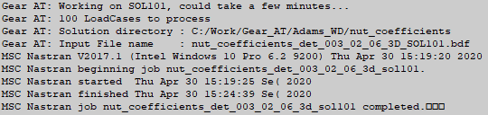
Figure 337 Launch of Nastran
The process of Figure 337 proceeds by execution of Gear AT op2-reader; see Figure 338. This processor reads the data stored by Nastran in the *.op2 file and appends retrieved data to the *.TLS file.
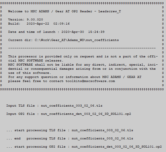
Figure 338 Execution Gear AT op2 - reader
If Nastran computation was not successful, Gear AT op2-reader should issue an information message and indicate unsuccessful termination. Please check the *.f06 file and mesher.log file; there you should find a hint about the cause of the abort by Nastran.
The button displays the contents of the *.TLP file.
displays the contents of the *.TLP file.The button  opens the Nastran bulk data file in Apex. Please, make sure you opt to Keep FE Mesh file in order to preserve Nastran input deck (*.bdf, *.dat) file. Figure 338 shows the example of mesh for a thread.
opens the Nastran bulk data file in Apex. Please, make sure you opt to Keep FE Mesh file in order to preserve Nastran input deck (*.bdf, *.dat) file. Figure 338 shows the example of mesh for a thread.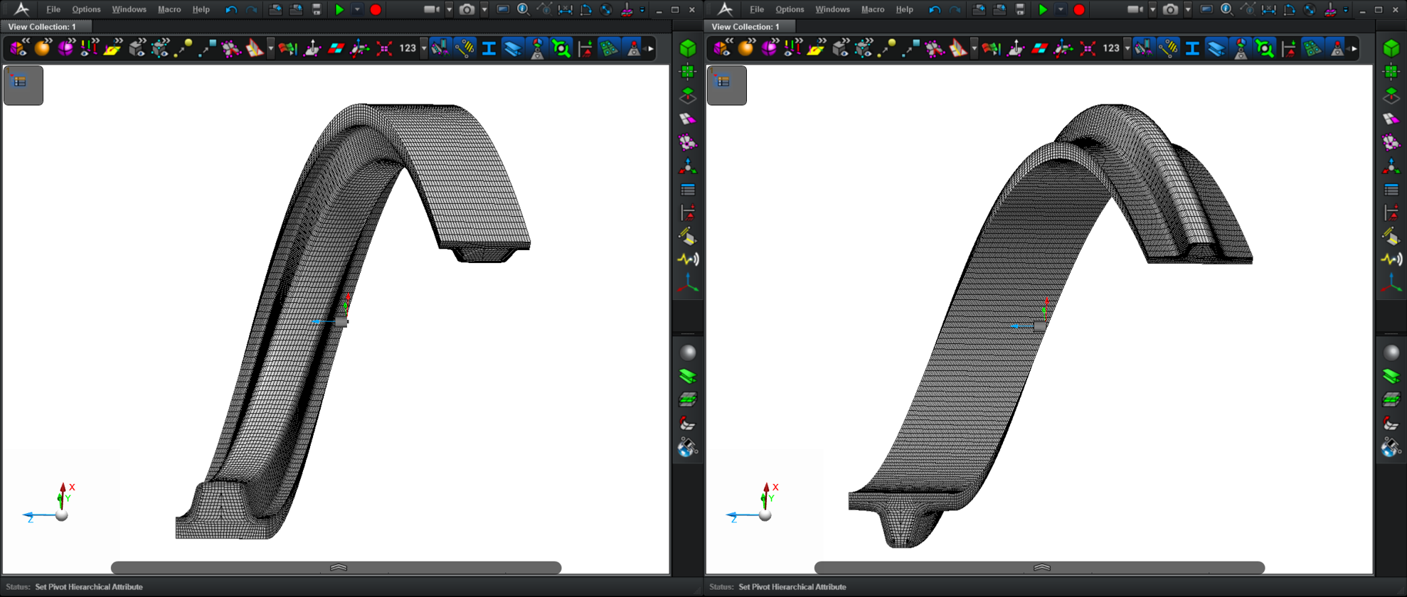
Figure 339 Nastran mesh of threads