Controlling the Animation Display
You can set many options for how animations appear on the screen:
Setting the View
Adams PostProcessor provides seven standard views of your animation or three-dimensional plot that you can display. The table below lists the views, their coordinate system orientations, and the tools on the Main toolbar that activate them. You can also redefine the orientations as explained in PPT Preferences - Orientation.
Standard Views
You can display the: | The default orientation is: | Its tool is: |
|---|---|---|
Front |  |  |
Back |  |  |
Top |  |  |
Left |  |  |
Right |  |  |
Bottom |  |  |
Isometric |  |  |
To set a view in a viewport:
1. Click the viewport you want to change.
2. Do one of the following: |
■On the View menu, point to Pre-Set, and then select a view.
 , and then select one of the
 Setting Display of Screen Icons
By default, Adams PostProcessor turns off all Screen icons during animations to speed up the animation. Displaying icons can be very helpful when debugging your model. For example, displaying screen icons during animations allows you to see if joints or forces applied to parts are behaving as expected because you can see their icons move as the animation progresses. Displaying screen icons can also help you see how coordinate system markers move during animations because they control the locations and directions for constraints and forces.
Note that if you import your animation through a Graphics file (.gra) only, you do not have joint or force icons.
You can also control the visibility of the part coordinate triad and the center of gravity marker as explained in PPT Preferences - Animation.
To display screen icons during an animation:
1. From the dashboard, select View.
2. Select Display Icons.
Tip: | On the Main toolbar, select |
Setting Display of Triad and Title
Triad
You can turn on the display of a triad that displays the orientation of the global coordinate system axes:

It appears in the lower left corner of a viewport containing an animation. As you move the view of a viewport, the triad displays the changes to the coordinate system orientation.
Title
You can also display a title for the animation in the upper left corner of the viewport. It displays the name of the model and the current frame number. During the animation, it displays the time. In addition, you can set it so it displays the number of frames per second.
To display triad during an animation:
1. From the dashboard, select View.
2. Select Display Triad.
To display title during an animation:
1. From the dashboard, select View.
2. Select Title.
3. To also display the number of frames per second, select FPS Title.
Changing Part Display
You can change the display of individual parts in your animation, including their visibility, color, icon size, and transparency.
To change the display of parts:
1. Select the part or parts to be changed.
2. In the Property Editor, set how you want the object displayed. (See Property Editor - Modeling Object.)
Zooming the Display
You can define the area of an animation or plot that you want enlarged and displayed in the current viewport. You draw a box to define the zoom area.
To define a zoom box:
1. On the View menu, point to Position/Orientation, and then select Zoom Box.
Tip: | On the Main toolbar, select  . . |
2. Place the cursor where you want the upper right corner of the box and click and hold down the left mouse button.
3. Drag the mouse diagonally to define the size of the box.
4. Release the mouse button.
Fitting the Display
You can automatically fit an animation or plot into the current viewport using the Fit and Fit - No Ground commands. Fit fits the entire model into the window, including the ground part and any geometry attached to it. Fit - No Ground excludes the ground part and its geometry.
For example, if you have a model of a car that also has a very large piece of geometry on ground representing a road, and you use Fit to view the entire model, the viewport contains all of the geometry, as shown in the image on the left in the following figure. It is difficult to observe the car after the fit operation with the ground included. If you use Fit - No Ground, the viewport is only of the car, as shown in the image on the right.
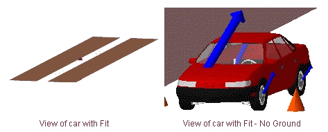
Car and Road with Fit and Fit - No Ground
To fit the entire animation into the viewport, including ground:
■On the View menu, point to Position/Orientation, and then select Fit.
Tip: | On the Main toolbar, select  . . |
To fit the animation, excluding ground, into the viewport:
■On the View menu, point to Position/Orientation, and then select Fit - No Ground.
Setting the Center of a Viewport
You can move a particular point in your animation or three-dimensional plot to the center of the current viewport. You can also reposition the model or plot so that the origin (0,0) of the window is again at the center of the viewport.
To set a particular point as the center of a viewport:
1. On the View menu, point to Position/Orientation, and then select Center.
Tip: | On the Main toolbar, select  . . |
2. Click the left mouse button on the point in the model that you want at the center of the window.
To return the origin (0,0) of the viewport to the center of the viewport:
■On the View menu, point to Position/Orientation, and then select Origin.
Setting the View Perspective
By default, Adams PostProcessor displays your animation or three-dimensional plot as though it were drawn on a flat piece of paper. This is called orthographic projection. You can change the depth of the screen to perspective projection. Perspective projection causes a vanishing point effect by showing the size of parts relative to their distance from the viewer. It does not show the true proportions of all parts.
To set the current viewport to perspective, do one of the following:
■On the View menu, point to Projection, and then select Perspective.
■From the dashboard, select View, and then select Perspective.
Tip: |


To set the perspective in the viewport:
1. On the View menu, point to Position/Orientation, and then select the Translate Z.
2. Place the cursor in the viewport and move the cursor upwards to increase perspective and downwards to decrease the perspective.
3. To stop setting the perspective, right-click the viewport.
Setting Rendering Mode of Animations
Adams PostProcessor provides four rendering modes in which you can display an animation in a viewport, as listed in the table below.
Rendering Modes
The mode: | Does the following: |
|---|---|
Wireframe | Shows only the edges of objects so that you can see through the objects. |
Shaded (flat) | Shaded, but polygon edges are visible. |
Smooth shaded | Shaded, with polygon edges not visible. |
Hidden-line removal | Shows only the edges of object. It does not show edges, or portions of edges, that are obscured by other geometry. |
To select a rendering mode:
1. Click the viewport whose rendering mode you want to change.
2. On the View menu, point to Render Mode, and then select a rendering mode.
Tip: | To toggle between shaded and wireframe, on the Main toolbar, select  . . |
Note: | If you are using the Native Open GL graphics driver, which is the default, only two modes have an effect: wireframe and smooth shaded. For more information on selecting graphics drivers, see Running and Configuring Adams. |
Specifying the Camera Perspective
You can change your viewing or camera perspective. For example, you can change the perspective to always look at a particular part as it moves or to always look from a particular vantage point, such as one that moves with a part. Setting different camera perspectives is particularly helpful when parts undergo large motions and move off your screen during an animation, such as with vehicle simulations.
A good example of setting the camera perspective is when you simulate a vehicle driving through a slalom course on a test track. By default, you view the simulation as a bystander alongside of the road whose gaze is fixed in one direction. As the vehicle moves forward, it quickly moves out of your field of view. You can, however, set the camera perspective to mimic the movement of your head as it moves to follow the vehicle. Furthermore, rather than observe the vehicle as a bystander alongside a road, you can also set the camera perspective to mimic what the driver sees as he or she looks out the front windshield of the vehicle.
To set the camera perspective:
2. Set the options as explained in the table below.
3. Select Lock Rotations to follow the rotations of the followed object.
Camera Perspective Options
To set the camera perspective to: | In the Follow Object text box: | Mount Camera At text box: |
|---|---|---|
Follow a moving point | Enter the marker that you want to follow during the animation. | Do not enter a marker. Leave it empty. |
Look from a movable point towards a stationary point | Enter a marker on a non-moving part or ground. | Enter a marker on a moving part. |
Look from one movable point to another | Enter the marker that you want to follow during the animation. | Enter the marker that you want to remain in the center of the screen during the animation. |
Setting Lighting
Adams PostProcessor has many lighting options to help you enhance the quality and realism of your animations. The options allow you to set:
■Overall intensity of the light (much like setting a dimmer switch in your home).
■Background, ambient light to control the diffusion of light sources to affect the amount of lighting on edges.
■Reflections off of parts. (Note that this is computationally expensive and can slow down your animations.)
■Focused lighting that comes from different directions, and define the angle of that lighting (how far it is from the center line). You can think of this as swinging a light boom across your model.
■Illumination of only one side of the geometry to speed up your animations.
To access the lighting options:
■From the dashboard, select View.
To set up overall light intensity, ambient lighting, and reflections:
1. Use the Light Intensity slider to set how bright the overall light is.
2. Use the Ambient Light slider to set the ambient light.
3. Toggle Light Reflections to set up reflections off of parts.
To set up focused lighting:
1. Use the light buttons on the right side of the dashboard to turn on different focused light sources.
Note: | The number of light sources you can select depends on the graphics driver and system you are using. If you selected OpenGL, the number of light sources depends on your graphics card. For more information on selecting graphics drivers, see Running and Configuring Adams. |
2. Use the Light Angle slider to set how far from the center line the light source is.
To set up one-side lighting:
■Clear the selection of Two-Sided Lighting.
Note: | To achieve the fastest animations, set the lighting options to either: No reflections; One-sided; or One light source. |