Using the Road Builder
The Road Builder lets you create and edit 3D Spline Road property files in XML format. It is available in Adams Car.
The following sections explain more about the Road Builder:
Conversion of TeimOrbit Format 3D Spline Road Property Files to XML Format
The Road Builder does not use TeimOrbit property files. If you open a TeimOrbit 3D Spline Road property file in the Road Builder, it automatically converts it to XML format. This XML 3D Spline Road property file is stored in the working directory and loaded in the Road Builder.
Starting the Road Builder
To start the Road Builder in Adams Car:
■From the Setup menu, point to Vehicle Environment, and then select Road Builder.
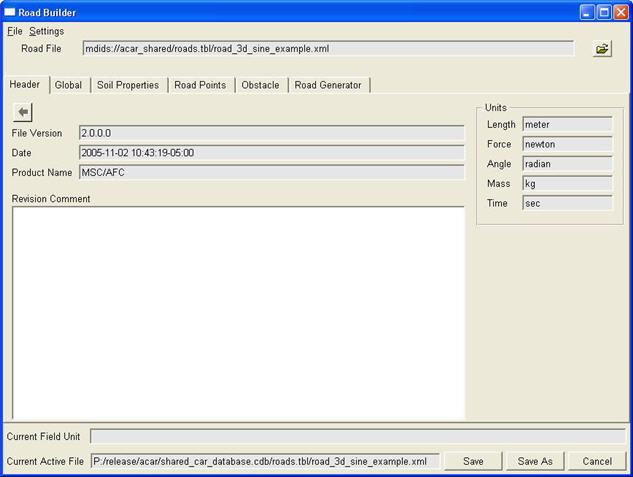
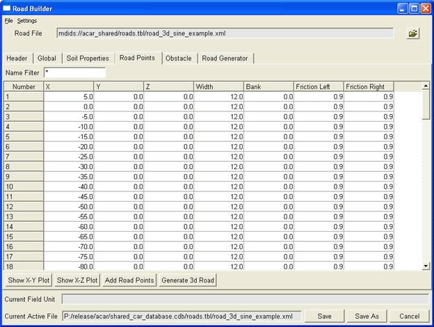
In both cases, the Road Builder starts with the road_3d_sine_example.xml example road property file loaded as shown in the figure below. The Road Builder consists of six tabs:
■Soil Properties - If road is used for the Soft Soil Tire model, the soil properties should be entered. Learn more.
Creating a 3D Spline Road Property File
To create a new 3D Spline Road property file:
■From the File menu, select New.
When you create a new 3D Spline Road property file, the default values of the road vertical are set to (0.0, 0.0, 1.0). Note that the road vertical is normalized at the Adams Solver level.
Opening an Existing 3D Spline Road Property File
To edit an existing 3D Spline Road property file, do one of the following:
■From the File menu, select Open, and then browse for the desired file.
■To the right of the Road File text box, select the Browse button  , and then browse for the desired file.
, and then browse for the desired file.Changing Units
To change the units:
1. From the Settings menu, select Units.
2. Change the units, and then select OK.
Saving Changes
To save changes you make to the XML file:
1. At the bottom of the Road Builder, select either Save or Save As.
2. If you selected Save As, enter the file name, and then select OK.
Displaying Header Information and Adding Comments
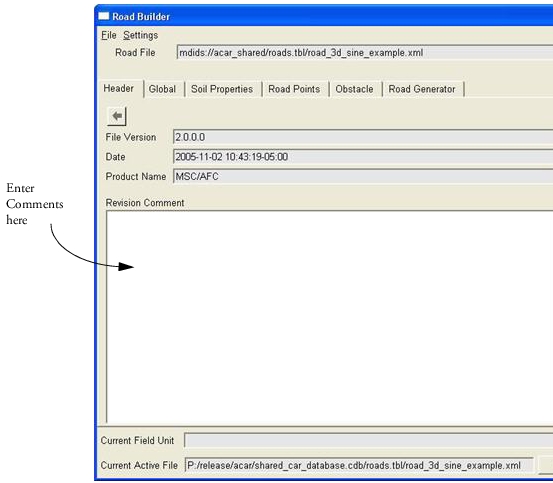
The Header tab shows information about the road file and the units of the 3D Spline Road object. You can add comments in the Revision Comment area, as shown in the figure below.
To display header information and add comments:
1. Select the Header tab.
2. View the information and in the Revision Comment area, enter any comments to help you manage the road property file.
Setting Global Parameters
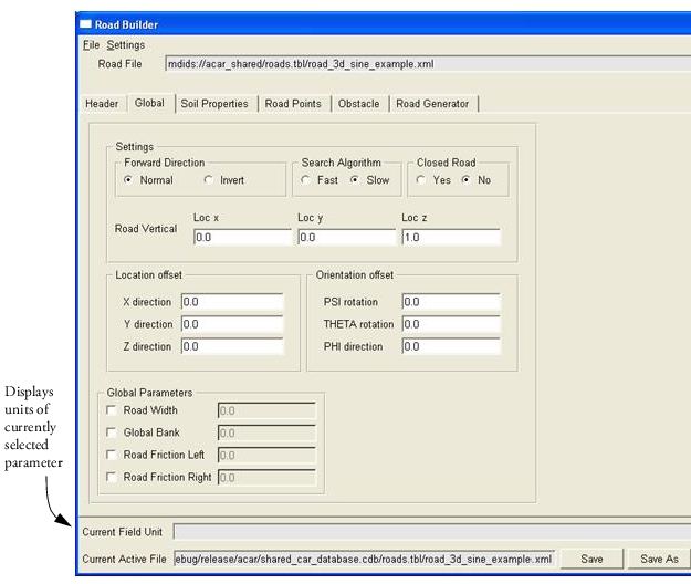
Parameters that apply to the entire road are defined in the Global Tab, shown below. Learn more about the global parameters.
To edit the parameters:
1. Select the Global tab.
Change the parameters as explained in Global Parameters.
Tip: | To help you correctly enter values, the units for the current parameter appear in the Current Field Unit text box. |
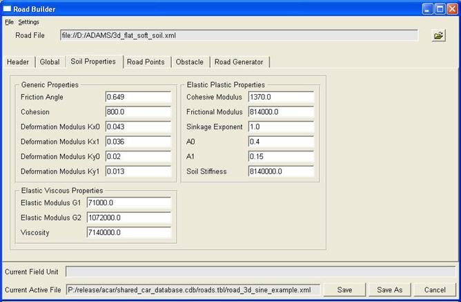
Setting Soil Properties
In case that the road is used for the Soft Soil Tire model the soil properties should be entered. These properties are used by the Soft Soil Tire model only: when the Soil Properties are in the road data file, but another tire model is used, they are ignored.
Note that the Soil Properties will be valid for the whole road area, no sections with specific other values can be defined.
Defining Road Data Points
The Road Points tab shows the Road Data Points table, as shown in the figure below. Learn about 3D Spline Road data points. Using the table, you can add and delete road data points and display the points as a plot so you can visualize the road and make changes to it.
Note: | The 3D Spline Road format is not designed to represent roads with large amount of data. Road types like OpenCRG or RGR are dedicated and have much better performance with large amounts of (measured) data points. |
Working with Data Rows
You can edit any of the data in the rows of the Road Data Points table and add or delete rows. The following provide you with the basics of enter data points in the table.
To edit the values in a row:
■Select the value you want to change, and then type a new value. Learn about the data point values.
To add rows to the Road Data Points table:
1. Select Add Road Points, located below the table.
2. Enter the number of data points you want to enter, and then select OK. The maximum number points that can be added is 3000.
The Road Builder adds the rows to the end of the table.
To delete rows in the Road Data Point table:
■Select the row or rows you want to delete, right-click the column Number, and then select Delete Row(s).
The Road Builder renumbers the rows of the table.
To add a single row to the end of the table:
■Right-click the column Number, and then select Add Row.
To insert a single row below a selected row:
■Right-click the row in the column below which you want to add a row, and then select Insert Row.
To copy and paste data in rows:
■Highlight the text you want to copy, and then select an copy (CTRL + C) data from a source and paste (CTRL + V) it in the road data points table.
Plotting Road Data Points
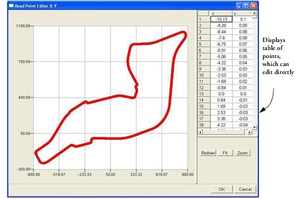
You can visualize the road data plots by plotting them as x-y (x values versus y values) or x-z plots (x values versus z values).
Note that if both the x-y plot and x-z plots are active, changes to road data points in one plot are not automatically updated in the other plot. Close and reopen the plot after updating the main road data points table.
To plot the road data points:
■Select Show X-Y Plot or Show X-Z Plot to create a plot of the road, as shown in the figure above for x-y values.
To fit the display of the plot into the plotting window, do one of the following:
■Select Fit.
■Right-click the plot, and then select Fit.
To view the data points in the plot:
■Right-click the plot, and then select Show Symbols.
■To view the data points as a curve:
■Right-click the plot, and then select Show Curve.
To zoom the display:
1. Select Zoom.
2. using the mouse, draw a box around the area of the plot you want to view.
To modify the road data points:
1. Right-click the plot, and then select Show Symbols.
2. Drag the points using the mouse. The new coordinates for the data points update in the table on the right.
3. Select OK. (The road data points are not updated in the main table until you select OK.)
To exit the plot:
■In the upper right corner, select the X.
Defining Obstacles
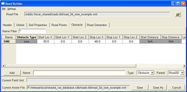
The Obstacle tab shows the 3D Spline Road obstacles (also called road perturbations). If there is more than one road obstacle, the Obstacle tab displays the Obstacle table, as shown in the figure below. If there is only one road obstacle, the Obstacle tab shows the Obstacle Property Editor. You can only create a new obstacle in the Obstacle table.
For each obstacle, all parameters are stored in the XML format 3D Spline Road property file. This will make it easy to change obstacle type for a particular obstacle if data already exists.
Adding, Deleting, and Renaming Obstacles
To create a new road obstacle in the Obstacle table:
1. In the Name text box, enter the name of the obstacle.
2. Select Add.
3. Enter the values for the obstacle as explained in Adams 3D Spline Road Perturbation Keywords.
To rename an obstacle:
■Right-click the obstacle name in the table, select Rename Obstacle, and then enter a new name.
To delete an obstacle:
■Right-click the obstacle name in the table, select Delete Obstacle.
Using the Obstacle Property Editor
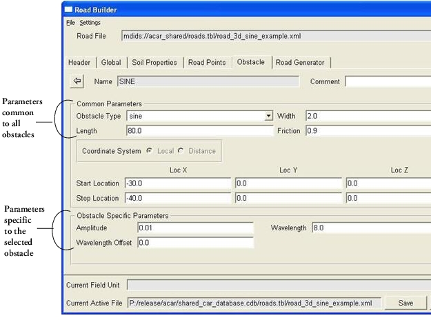
The Obstacle Property Editor, shown in the figure below, shows the common and obstacle-specific parameters. The obstacle-specific parameters portion of the dialog box only shows those parameters that belong to the selected obstacle type.
Note that you cannot change the coordinate system in the Common Obstacle portion as the obstacle type determines whether Local or Distance should be used.
You manage the data in the tables for the Polyline and Crown obstacle types in the same way you do road data points. For more information on adding, deleting, and copying/pasting of data, see Defining Road Data Points.
To display the Obstacle Property Editor, do one of the following:
■Right-click the obstacle name in the Obstacle table, and then select Modify with PropertyEditor.
■Double-click the obstacle name in the obstacle table.
To return to the Obstacle table:
■Click the arrow  at the top left side.
■To edit the values:
■Change the values as explained in Adams 3D Spline Road Perturbation Keywords.
Tip: | To help you correctly enter values, the units for the current parameter appear in the Current Field Unit text box. |
Converting a Rougness Obstacle
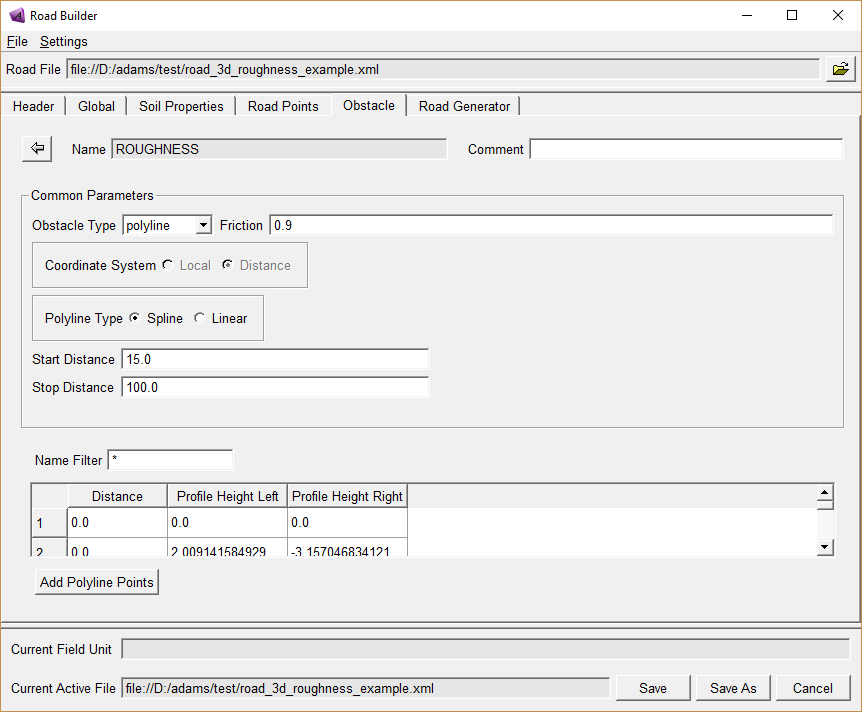
When a road contains an obstacle of type Roughness, it can be converted to a Polyline obstacle in the obstacle editor by the 'Convert Roughness to Polyline' button.
In that case the Roughness obstacle, which is using the Sayers road model (see 'Keywords for Roughness Perturbation Type'), will be converted to a polyline obstacle which exists of two series (left and right track) of road height points as function of travelled distance. A Roughness obstacle may have varying road heights due to the seed value; the Polyline obstacle will have fixed road height data series, but still have the properties of the Sayers road model.
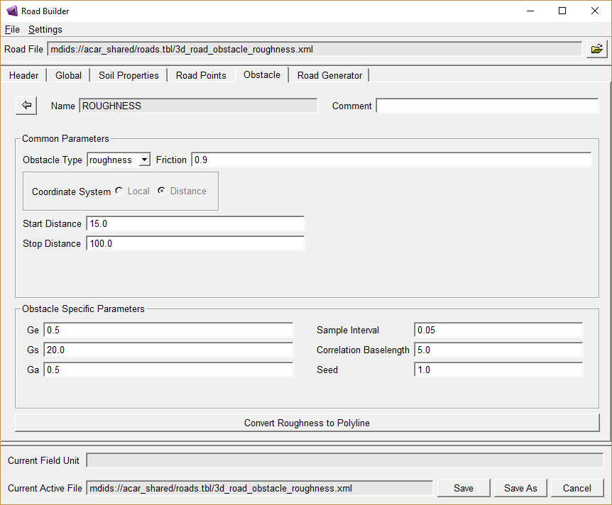
When clicking the 'Convert Rougness to Polyline' button, following dialog will appear with the polyline obstacle.
Defining Analytical Road
Following example illustrates how to create/modify a road model analytically from scratch in Adams Road Builder. Road data can be created with multiple segments, each segment representing predefined formulations like Linear, Curvature, and Transition Curve or through User Defined Functions and User Defined Points.
Steps to Create a Road Data File:
New tab Road Generator is added to the Road Builder GUI. This tab allows the user to create/modify road data file using segments.
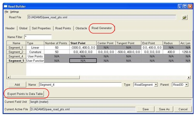
To create a new segment, enter segment name in the Name field and click Add button. Segment name should be unique. To make it easier for the user to create road profile, some basic functions were created. User can use these functions by giving appropriate values.
To see the road points click on Export points to Data Table this will calculate the road points according to the segment function and export them to the Road Points tab in the GUI.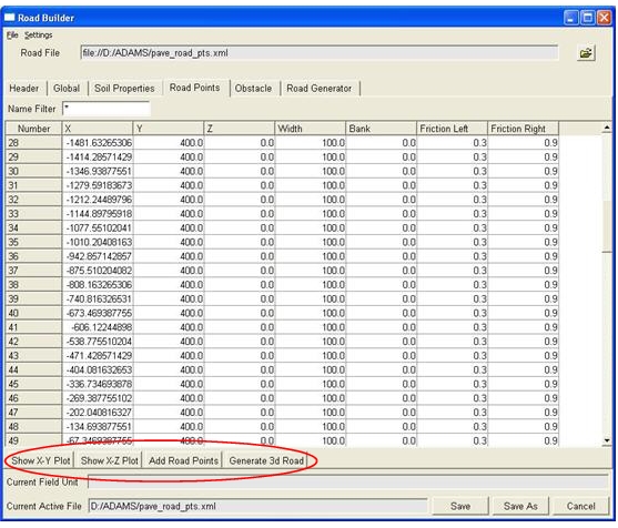
To see the road points in 2D click button Show X-Y Plot & Show X-Z Plot. To see the road profile with shell graphics click on Generate 3d Road. To see in 3D, user should have Adams Car license.
Description of Functions:
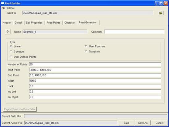
Linear:
This function will create a straight line between two given points. Inputs required are Number of points, Start point, End point, Width, Bank, mu Left and mu Right.
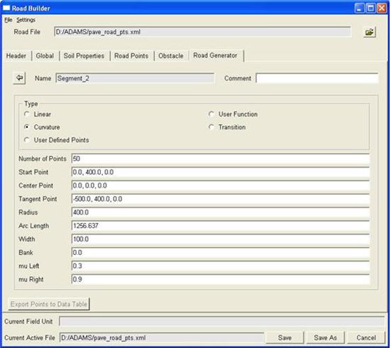
Curvature:
This function will create a curve. Inputs required for this function are Number of Points, Start point, Center point, Tangent Point, Radius, Arc Length, Width, Bank, mu Left and mu Right.
Transition:
This function will connect the start and end point of the road. Inputs required for this are segment 1, segment 1 point, segment 2, segment 2 point, Width, Bank, mu Left and mu Right.
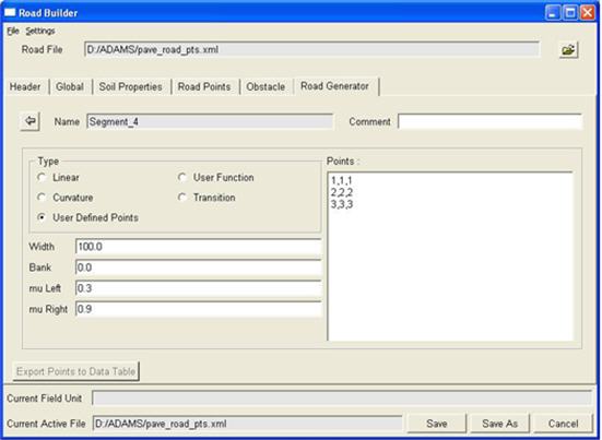
User Defined Points:
This functionality allows the user to define their road points directly. This functionality is more useful in the case when a user wants to use the existing road point which is already in the old road data file format.
The points are appended to the road points table.
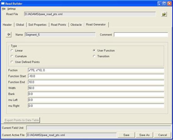
User Defined Functions:
User can calculate points using their own functions.
For example:
User function = s*75; s*10; 0
Function Start = -10
Function End = 10
Calculation of Road Point:
-10*75; -10*10; 0
-9*75; -9*10; 0
-8*75; -8*10; 0
Notes: | The transition element is a powerful element that takes care of a smooth transition in between two elements! It is capable of connecting sections with different width and inclination. A recommended practice is to use this element in between two other elements or at the end of a 'closed' road so that the end of the road has a smooth connection to the beginning of the road. The following list of elements illustrates the usefulness of the transition element: 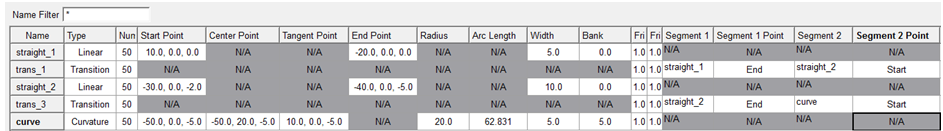 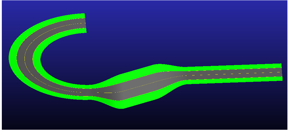 |