Adams Tire 3D Spline Road Model
Learn how to use the Adams 3D Spline Road model to define a road:
About Adams 3D Spline Road
Adams 3D Spline Road lets you define an arbitrary three-dimensional smooth road surface, such as parking structures, racetracks, and so on. A smooth road is a road surface with a curvature, which is less than the curvature of the tire. In addition, Adams 3D Spline Road lets you model three-dimensional road obstacles, which are placed on top of the underlying smooth road surface.
The road centerline, width, bank angle, and left and right friction levels define the road surface completely. The road data is stored in an XML file, which you can create and modify using the Road Builder (Learn more about Using the Road Builder). The legacy TeimOrbit road definition file (.rdf) is still supported, and can be translated to XML using the Road Builder. For a description of the information contained in the .rdf file, see About the Adams 3D Spline Road Property File.
By specifying the coordinates of the road centerline, you can construct any line in three-dimensional space. Adams 3D Spline Road assumes a flat cross-section for which the bank angle and width can be specified for each data point. In addition, you can specify friction levels for left and right road sides.
Using Adams 3D Spline Road
You can reference the Adams 3D Spline Road just as you do any other .rdf by selecting your desired road from an appropriate database. In addition, Adams Car have a Adams 3D Spline Road event, called 3D Spline Road. Graphics for the road are automatically generated for animation purposes.
In the current version of Adams 3D Spline Road, Adams Car offer multiple methods to access the Adams 3D Spline Road capabilities:
■When running any full vehicle simulation you may use an Adams 3D Spline Road data file for the road.
■When using with Driving Machine, you may also use a road data file as you would a driver control data (.dcd) file to specify the vehicle path. The Driving Machine will then drive the vehicle along the centerline of the road.
■When using with Adams SmartDriver, you can use the road data file to replace the driver road data (.drd) file. In this case, the vehicle will use the x, y, and z road centerline to define the vehicle path.
Examples of event (.xml) file for use with Driving Machine and Adams SmartDriver are shown next:
For Driving Machine:
<DcfMini name="3D_SMOOTH_ROAD" active="true"
userDefined="false" smoothingTime="0.1"
activeFlag="true" abortTime="1"
stepSize="0.01" hMax="0"
>
<DcfDemand name="steering" active="true"
userDefined="false"
demandType="steering"
actuatorType="rotation"
controlMethod="machine"
controlMode="absolute"
controlType="constant"
constantValue="0" initialValue="0" finalValue="0"
startTime="0" duration="0" rampValue="0"
maximumValue="0" cycleLength="0" amplitude="0"
initialFrequency="0" frequencyRate="0"
maximumFrequency="0" functionString="0"
>
…
<DcfMachine name="machine" active="true"
userDefined="false"
steerControl="file"
dcdSteerFile="mdids://acar_shared/roads.tbl/3d_road_smooth_ramp.xml"
steerRadius="0"
steerEntry="0"
turnDirection="right"
pathPositioning="default"
speedControl="lon_accel"
velocity="0" acceleration="0" jerk="0"
startTime="0.1"
samplePeriod="0.01"
>
For Adams SmartDriver:
DcfMini name="3D_SMOOTH_ROAD" active="true"
userDefined="false" smoothingTime="0.1"
activeFlag="true" abortTime="1"
stepSize="0.01" hMax="0"
>
<DcfDemand name="steering" active="true"
userDefined="false"
demandType="steering"
actuatorType="rotation"
controlMethod="SmartDriver"
controlMode="absolute"
controlType="constant"
constantValue="0" initialValue="0" finalValue="0"
startTime="0" duration="0" rampValue="0"
maximumValue="0" cycleLength="0" amplitude="0"
initialFrequency="0" frequencyRate="0"
maximumFrequency="0" functionString="0"
>
…
<DcfSmartDriver name="smartdriver" active="true"
userDefined="false" task="vehicle_limits"
courseFile="mdids://acar_shared/roads.tbl/3d_road_smooth_ramp.xml"
max_driving_accel="70" max_braking_accel="70"
max_lh_turn_accel="70" max_rh_turn_accel="70"
samplePeriod="0.01"
/>
Adams 3D Spline Road Perturbation Types
The available road perturbations are:
■CROWN - Road crown along the road centerline.
■CURB - Curb at left, right, or both sides of the road.
■PLANK - Single plank with beveled edges or rounded corners.
■POLYLINE - Cubic spline description of the road profile for left and right wheel track.
■POTHOLE - Pothole of rectangular shape.
■RAMP - Ramp, either rising or falling.
■ROOF - Roof-shaped, triangular obstacle.
■ROUGHNESS - Generated irregular road profiles with stochastic properties similar to measured roads.
■SINE - Sine wave with constant amplitude and wavelength.
■SWEEP - Sine wave with variable amplitude and wavelength.
■GRID - Regular Grid obstacle, the road height is defined by a matrix of road height points at equal distance
Note that a specific contact method has to be selected, which defines how Adams 3D Spline Road interacts with the tires. Not all combinations of road, tire, and contact methods are permitted. For more information, see the topics under Tire Model in the Table of Contents.
Be aware that Adams 3D Spline Road perturbations can generally have small wavelength content. Therefore, the combination of tire and contact methods should be able to handle this type of excitation.
Any number of perturbations can be defined. If an overlap exists between the perturbations, then Adams 3D Spline Road superpositions the perturbations.
Adams 3D Spline Road Perturbation Keywords
The following sections explain the keywords for each perturbation type and those independent of the perturbation type:
Keywords Independent of Perturbation Type
You must specify the following data in the .rdf file, independent of the type of perturbation.
Keywords Independent of Perturbation Type
Keyword: | Description: |
|---|---|
COORDINATE_SYSTEM | The type of coordinate system: ■local for a local perturbation-bound coordinate system. ■distance if the perturbation is defined along the length of the road. |
START | The start position of the perturbation. ■'0.0 0.0 0.0' for a local coordinate system. ■'0.0' for a distance-defined perturbation. |
STOP | The stop position of the perturbation. ■'1.0 0.0 0.0' for a local coordinate system. ■'1.0' for a distance-defined perturbation. |
LENGTH | The length of the perturbation. LENGTH is used in defining the local coordinate system. |
WIDTH | The width of the obstacle. The obstacle width can be specified independently of the road width. |
FRICTION | The friction coefficient of the obstacle. |
ROAD_TYPE | The perturbation type. |
Coordinate System Keywords
Depending on the COORDINATE_SYSTEM keyword you selected as shown in Keywords Independent of Perturbation Type, you can use two types of coordinate systems:
■Local coordinate system - The START and STOP keywords define the local coordinate system, while the interconnecting line and the LENGTH keyword provide the direction of the perturbation. Adams 3D Spline Road projects the road profile height in the local coordinate system onto the smooth road surface.
■Distance coordinate system - The START and STOP positions are expressed in distance along the road centerline or chord length. The direction and length are, therefore, defined implicitly.
Along the START-STOP vector, the centerline of the perturbation/obstacle is defined. With START, the starting location of the perturbation (centerline) is defined. With STOP the direction/orientation of the perturbation is given. The length of the perturbation is defined by LENGTH, not by the length of the START-STOP vector.
The following combinations of coordinate system and perturbation types are valid:
Valid Combinations of Perturbation Type and Coordinate System
Perturbation type: | Coordinate system: | |
|---|---|---|
Local: | Distance: | |
CROWN | X | |
CURB | X | |
PLANK | X | |
POLYLINE | X | |
POTHOLE | X | |
RAMP | X | |
ROOF | X | |
ROUGHNESS | X | |
SINE | X | |
SWEEP | X | |
GRID | X | |
Keywords for Crown Perturbation Type
If ROAD_TYPE = 'CROWN', then you must specify the keyword DATA_BLOCK = 'CROWN DATA', with the name of the subblock (CROWN_DATA). The subblock consists of three columns of numerical data:
■The first column is a set of distance-values in ascending order.
■The second column contains the height of the crown.
■The third column contains the crown coefficient.
The road profile height is a function of width-coordinates
 , obstacle width
 , height
 , and crown coefficient
 :
:
is a function of width-coordinates, obstacle width, height, and crown coefficient: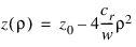
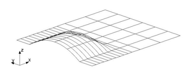
Illustration of Crown
Keywords for Curb Perturbation Type
If ROAD_TYPE = 'CURB', then you must specify the following keywords.
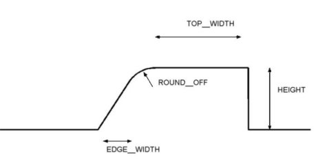
Illustration of Curb Keywords
Keywords for Curb Perturbation Type
Keyword: | Description: |
|---|---|
HEIGHT | Height of the curb(s). |
ROUND_OFF | Round-off radius of the top of the curb. |
TOP_WIDTH | The width of the top of the curb. |
EDGE_WIDTH | The width of the edge of the curb. |
SIDE | The side of the road where the curb is positioned: ■LEFT ■RIGHT ■BOTH |
Keywords for Plank Perturbation Type
If ROAD_TYPE = 'PLANK', then you must specify the following keywords.
Illustration of Edged Plank
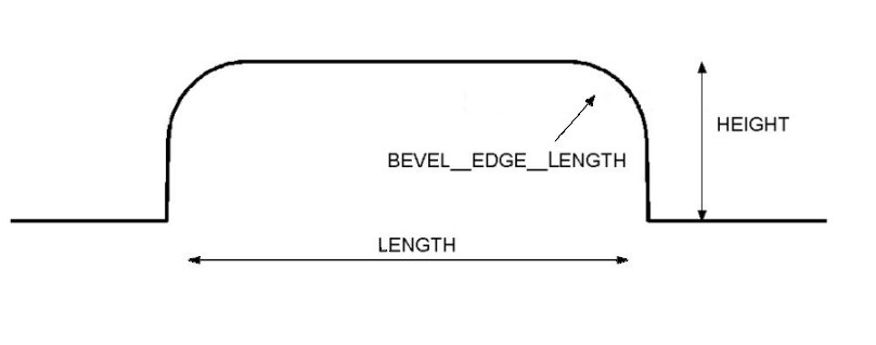
Illustration of Rounded Plank
Keywords for Plank Perturbation Type
Keyword: | Description: |
|---|---|
HEIGHT | Height of the plank. |
BEVEL_EDGE_LENGTH | Length of the beveled edge. A beveled edge has a 45º slope. When BEVEL_EDGE_LENGTH < 0, 3D Spline Road uses rounded corners instead of beveled edges. In this case, the radius of the corner is |BEVEL_EDGE_LENGTH|. |
Keywords for Polyline Perturbation Type
If ROAD_TYPE = 'POLYLINE', then you must specify the keyword DATA_BLOCK = 'XZ_DATA', with the name of the subblock (XZ_DATA). The subblock consists of three columns of numerical data:
■The first column is a set of distance-values in ascending order.
■The second and third columns contain the road profile height of the left and right tracks, respectively.
With the keyword POLY_TYPE the type interpolation in between the datapoints can be specified.
Keyword: | Description: |
|---|---|
POLY_TYPE | 'SPLINE', a cubic spline will be used for interpolation in between the datapoints (default). 'LINEAR', a linear interpolation will be applied (same as 2D Road) |
Keywords for Pothole Perturbation Type
If ROAD_TYPE = 'POTHOLE', then you must specify the 'DEPTH' keyword, which specifies the depth of the pothole.
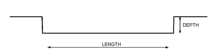
Illustration of Pothole keywords.
Keywords for Ramp Perturbation Type
If ROAD_TYPE = 'RAMP', then you must specify the following keywords.
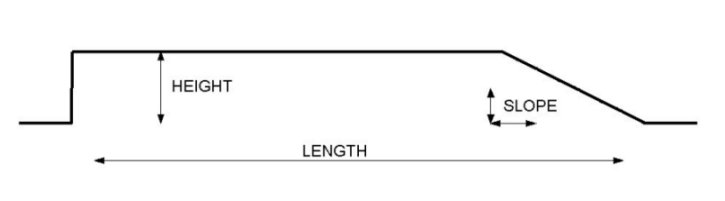
Illustration of Ramp keywords.
Keywords for Ramps Perturbation Type
Keyword: | Description: |
|---|---|
HEIGHT | Height of the ramp. |
SLOPE | Slope of ramp. 1 corresponds to 45º. |
Keywords for Roof Perturbation Type
If ROAD_TYPE = 'ROOF', then you must specify the following keywords.
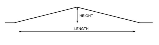
Illustration of Roof keywords.
Keywords for Roof Perturbation Type
Keyword: | Description: |
|---|---|
HEIGHT | Height of the roof. |
LENGTH | Length of the base of the triangular roof. |
Keywords for Roughness Perturbation Type
The roughness perturbation type uses a mathematical model developed by Sayers (1.). The model is empirical; it is based on the observed characteristics of many measured profiles of roads of various types. The model provides the synthesis of profiles for both the left and right wheel tracks.
If ROAD_TYPE = 'ROUGHNESS', then you must provide the following keywords:
Keywords for Roughness Perturbation Type
Keyword: | Description: |
|---|---|
GE | Elevation PSD parameter. |
GS | Velocity PSD parameter. |
GA | Acceleration PSD parameter. |
SAMPLE_INTERVAL | The distance between the road profile data points. |
CORRELATION_BASELENGTH | Correlation base length for filtering (recommended value = 5.0 m). |
SEED | Seed for random numbers. ■If seed is negative, the computer's clock is used as a seed. An infinite number of profiles can be generated to match the same set of Sayers-model parameters. ■If seed is greater than zero, the value of the seed is used as the seed to the random-number generator. This is a means of generating reproducible profiles with the Sayers model. |
More detailed information found on the section Road-Profile Generation Tool in Adams Car Ride.
References:
1. Sayers, M.W., "Dynamic Terrain Inputs to Predict Structural Integrity of Ground Vehicles." UMTRI Report No. UMTRI-88-16, April 1988, 114 pp.
Keywords for Sine Perturbation Type
If ROAD_TYPE = 'SINE', then you must provide the following keywords.
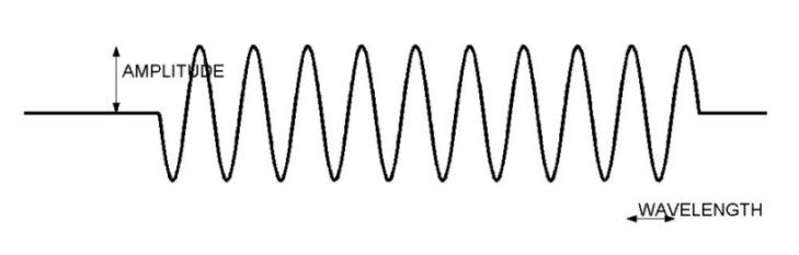
Illustration of Sine keywords
Keywords for Sine Perturbation Type
Keyword: | Description: |
|---|---|
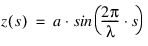
AMPLITUDE | Amplitude of the sine wave (a). |
WAVE_LENGTH | Wave length of the sine wave (l). |
The road profile height z, is given by:
Keywords for Sweep Perturbation Type
If ROAD_TYPE = 'SWEEP', then you must provide the following keywords.
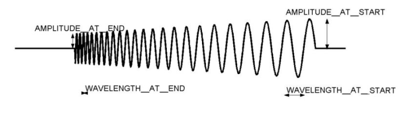
Illustration of Sweep Keywords
Keywords for Sweep Perturbation Type
Keyword: | Description: |
|---|---|
AMPLITUDE_AT_START | Amplitude of the sine wave at start (as  ). ). |
AMPLITUDE_AT_END | Amplitude of the sine wave at end (ae  ). ). |
WAVE_LENGTH_AT_START | Wave length of the sine wave at start (ls  ). ). |
WAVE_LENGTH_AT_END | Wave length of the sine wave at end (le  ). ). |
SWEEP_TYPE | ■SWEEP_TYPE = 0, then frequency changes linearly. ■SWEEP_TYPE = 1, then frequency changes logarithmically. Depending on the value of SWEEP_TYPE, the road profile height is given by the following functions: ■Linear sweep - The frequency changes linearly with distance s. The road profile height z is given by: 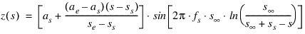 ■Logarithmic sweep - With every cycle, the wavelength decreases by a constant factor. The road profile is given by: 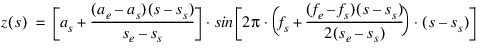 where 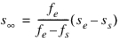  is the distance at which, theoretically, an infinitely high frequency is reached, with respect to the start is the distance at which, theoretically, an infinitely high frequency is reached, with respect to the start  . . |
Keywords for Grid Perturbation Type
If ROAD_TYPE = 'GRID', then you must specify the keyword DATA_BLOCK = 'GRID DATA', with the name of the sub block (GRID_DATA). The sub block should contain the road height data points as function of the x- and y- position. The local start coordinates will correspond to the first row and the center column will run along the line from START to STOP. In the example below, the z13 corresponds to the local START coordinates. Column 3 will be along the START to STOP direction.
z11 z12 z13 z14 z15
z21 z22 z23 z24 z25
z31 z32 z33 z34 z35
z41 z42 z43 z44 z45
z51 z52 z53 z54 z55
z61 z62 z63 z64 z65
z71 z72 z73 z74 z75
z81 z82 z83 z84 z85
z91 z92 z93 z94 z95
The lateral distance between two points in a row is determined by the WIDTH of the obstacle and the number of points in a row:
distance_y = WIDTH / (number of points in a row -1)
Similar, the longitudinal distance between two points in a column is determined by the LENGTH of the obstacle and the number of points in a column:
distance_x = LENGTH / (number of points in a column -1)
3D Spline Road will calculate the road height using cubic splines through the road height data points.
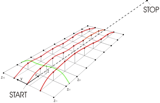
Illustration of Grid keywords.
About the Adams 3D Spline Road Property File
The following sections explain the data blocks in the Adams 3D Spline Road property file (.rdf). The last section contains a sample .rdf.
File Details
The first block of data, [MDI_HEADER], describes the TeimOrbit file:
[MDI_HEADER]
FILE_TYPE = 'rdf'
FILE_VERSION = 5.00
FILE_FORMAT = 'ASCII'
{COMMENTS}
'User entered comments go here'
MDI_HEADER Keywords
The keywords: | Contains: |
|---|---|
FILE_TYPE | The file type. |
FILE_VERSION | Version of file; to be changed when modifications to this file are made. |
FILE_FORMAT | The format of the data; for TeimOrbit, this is always ASCII. |
{COMMENTS} 'User entered comments go here' | Descriptive comments about the file, such as what road this represents, when the data was acquired, and so on. |
Units Details
The [UNITS] blocks defines the units for the road:
[UNITS]
LENGTH = 'meter'
FORCE = 'newton'
ANGLE = 'radian'
MASS = 'kg'
TIME = 'sec'
[UNITS] Keywords
The keywords: | Specifies: |
|---|---|
LENGTH | Unit of length. |
FORCE | Unit of force. |
ANGLE | Angle in radian or degree. |
MASS | Unit of mass. |
TIME | Unit of time. |
Model Details
The [MODEL] block defines the road model and version:
[MODEL]
METHOD = '3D_SPLINE'
VERSION = 1.00
[MODEL] Keywords
The keyword: | Determines: |
|---|---|
METHOD | Road contact algorithm that Adams Tire uses. You must set method='3D_SPLINE' to instruct Adams Tire to use the Adams 3D Spline Road spline algorithm. |
VERSION | Version of 3D_SPLINE algorithm being used; currently, 1.00. |
Global Parameters
The [GLOBAL_PARAMETERS]block defines parameters applying to the entire road.
[GLOBAL_PARAMETERS]
CLOSED_ROAD = 'NO'
SEARCH_ALGORITHM = 'FAST'
ROAD_VERTICAL = '0.0 0.0 1.0'
FORWARD_DIR = 'NORMAL'
MU_LEFT = 0.5
MU_RIGHT = 0.6
WIDTH = 5.000
BANK = 0.0
[GLOBAL_PARAMETERS) Keywords
The keyword: | Specifies: |
|---|---|
CLOSED_ROAD | Whether the road is closed or open. If the road is not structured to be closed (the beginning and end of the road are not facing each other) and you select the closed option, Adams Tire creates a deformed road. ■YES - The road is closed. ■NO - The road is open. |
SEARCH_ALGORITHM | The type of algorithm to be used to determine the contact location. For smooth roads, we recommend Fast algorithm. ■FAST - Specifies Fast algorithm.With Fast algorithm, caching is used if the input point is within  [m] distance from the previous input point. [m] distance from the previous input point.■SLOW - Specifies Slow algorithm. With Slow algorithm, no caching is used and the greatest accuracy is achieved. |
ROAD_VERTICAL | Vector specifying the z-axis of the user-coordinate system with respect to ISO-coordinate system. This option allows you to specify the road data points in your preferred reference frame. During simulation, Adams Tire converts all the data points to the ISO-reference frame based on the ROAD_VERTICAL values: '0.0 0.0 1.0' - The z-axis of user-reference frame with respect to ISO reference frame. |
FORWARD_DIR | Forward direction of the road: ■NORMAL - Vehicle travels along the specification of road data point. ■INVERT - Vehicle travels in a direction opposite to that of specified road data points. |
MU_LEFT | Road friction value on the left side of the road with respect to the centerline of the road. Specifying road friction under [GLOBAL_PARAMETERS] overwrites any specification of road friction values in the [DATA_POINTS] block. See Data Points Information. |
MU_RIGHT | Road friction value on the right side of the road with respect to the centerline of the road. Specifying road friction under [GLOBAL_PARAMETERS] overwrites any specification of road friction values in the [DATA_POINTS] block. See Data Points Information. |
WIDTH | Width of the road. If you specify WIDTH, it takes precedence over the WIDTH value specified in the [DATA_POINTS] block. Even if this parameter is set, you must specify the WIDTH parameter in [DATA_POINTS]. If this parameter is not required, then you can omit it from the road data file (.rdf). See Data Points Information. |
BANK | Slope angle of the road around its centerline in each data point. Zero bank means a horizontal width line. A positive value specifies a slope along a clockwise direction in ISO-reference frame. If you specify this dimension, then it takes precedence over the BANK value specified in the [DATA_POINTS] block. Even if you set this dimension, you must specify a BANK value. If this dimension is not required, then you can omit it from the .rdf file. See Data Points Information. |
Road Repositioning
The position and orientation of the road can be changed by defining the reference system in the optional [REFSYS] block:
Keyword: | Description: |
|---|---|
OFFSET | Three values, respectively the translational offset value in longitudinal direction, the translational offset value in lateral direction and the translational offset value in vertical direction, all default 0. |
ROTATION_ANGLE_XY_PLANE | The rotational offset around the Z-axis, default 0. |
In the TeimOrbit formatted road property file, this section will list as follows:
$-------------------------------------------------------------refsys
[REFSYS]
OFFSET = 1.0 0.0 0.3
ROTATION_ANGLE_XY_PLANE = 25.0
Data Points Information
The [DATA_POINTS] block contains the road information in a tabular form. The following information needs to be supplied for each entry.
[DATA_POINTS]
{ X Y Z WIDTH BANK MU_LEFT MU_RIGHT OBSTACLES }
[DATA_POINTS] Keywords
The keyword: | Specifies: |
|---|---|
X | X coordinate of sampled road data point. |
Y | Y coordinate of sampled road data point. |
Z | Z coordinate of sampled road data point. |
WIDTH | Width of road at the sampled point. |
BANK | Angle of road at the sampled point; positive value specifies a slope along a clockwise direction in ISO-reference frame. |
MU_LEFT | Road friction on the left side of road with respect to the centerline of the road at the sampled point. |
MU_RIGHT | Road friction on the right side of road with respect to the centerline of the road at the sampled point. |
OBSTACLES | The name of block that contains the perturbation information. This entry is optional. |
Sample Road Data File
$--------------------------------------------------------MDI_HEADER
[MDI_HEADER]
FILE_TYPE = 'rdf'
FILE_VERSION = 5.00
FILE_FORMAT = 'ASCII'
(COMMENTS)
{comment_string}
'Example of 3d Smooth road'
$------------------------------------------------------------UNITS
[UNITS]
LENGTH = 'meter'
FORCE = 'newton'
ANGLE = 'radian'
MASS = 'kg'
TIME = 'sec'
$--------------------------------------------------------DEFINITION
[MODEL]
METHOD = '3D_SPLINE'
$---------------------------------------------------ROAD_PARAMETERS
[GLOBAL_PARAMETERS]
CLOSED_ROAD = 'NO'
SEARCH_ALGORITHM = 'FAST'
ROAD_VERTICAL = '0.0 0.0 1.0'
FORWARD_DIR = 'NORMAL'
MU_LEFT = 0.5
MU_RIGHT = 0.5
WIDTH = 5.000
BANK = 0.0
$-------------------------------------------------------------REFSYS
[REFSYS]
OFFSET = 1.0 0.0 0.3
ROTATION_ANGLE_XY_PLANE = 25.0
$-------------------------------------------------------DATA_POINTS
[DATA_POINTS]
{ X Y Z WIDTH BANK MU_LEFT MU_RIGHT OBSTACLES }
12.50000E+00 4.60432E-15 0.00000E-00 7.000 0.000 0.900 0.900
10.50000E+00 4.60432E-15 0.00000E-00 7.000 0.000 0.900 0.900
5.50000E+00 4.60432E-15 0.00000E-00 7.000 0.000 0.900 0.900 CROWN
0.50000E+00 4.60432E-15 0.00000E-00 7.000 0.000 0.900 0.900
1.53081E-18 1.42109E-17 0.00000E-00 7.000 0.000 0.900 0.900
-2.50000E+00 4.68958E-16 0.00000E-00 7.000 0.000 0.900 0.900
-5.00000E+00 9.37916E-16 0.00000E-00 7.000 0.000 0.900 0.900
-7.50000E+00 1.39266E-15 0.00000E-00 7.000 0.000 0.900 0.900
-1.00000E+01 1.84741E-15 0.00000E-00 7.000 0.000 0.900 0.900
-1.25000E+01 2.30216E-15 0.00000E-00 7.000 0.000 0.900 0.900
-1.50000E+01 2.77112E-15 0.00000E-00 7.000 0.000 0.900 0.900
-1.75000E+01 3.22586E-15 0.00000E-00 7.000 0.000 0.900 0.900
-2.00000E+01 3.69482E-15 0.00000E-00 7.000 0.000 0.900 0.900
$-----------------------------------------------------END_DATA_POINTS
[CROWN]
COORDINATE_SYSTEM = 'distance'
START = 7
STOP = 16
WIDTH = 4
ROAD_TYPE = 'CROWN
DATA_BLOCK = 'CROWN_DATA'
FRICTION = 0.900
(CROWN_DATA)
{S HEIGHT CROWN}
7.00000E+00 0.00000E+00 0.00000E+00
8.00000E+00 1.25000E-02 3.12500E-03
9.00000E+00 5.00000E-02 1.25000E-02
1.00000E+01 8.75000E-02 2.18750E-02
1.10000E+01 1.00000E-01 2.50000E-02
1.20000E+01 1.00000E-01 2.50000E-02
1.30000E+01 1.00000E-01 2.50000E-02
1.40000E+01 1.00000E-01 2.50000E-02
1.50000E+01 1.00000E-01 2.50000E-02
1.60000E+01 1.00000E-01 2.50000E-02
Road Normal calculation and Road Boundaries
The road normal calculation of 3D Spline road is based on the road geometry of the smooth road, not on the superimposed obstacles. If one would need to include the effect of the obstacles, following environment variable needs to be set:
MSC_ADAMS_TIRE_OBSTACLE_NORMAL=YES
When a wheel passes a road boundary (kerbside), the wheel-road contact will be lost and thus the vehicle will start to drop down. The solver may encounter stability problems in some cases and start reducing step size or even run into stability problems. By setting the environment variable MSC_ADAMS_TIRE_ROAD_EDGE_STOP solver will abort the simulation if a wheel passes a road boundary:
MSC_ADAMS_TIRE_ROAD_EDGE_STOP=YES
Another feature of 3D Spline road can be used to avoid the loss of wheel-road contact outside the road boundaries: setting the environment variable MSC_ADAMS_TIRE_ROAD_KEEP_LEVEL will cause 3D Spline Road to keep the road height also beyond the road boundaries.
MSC_ADAMS_TIRE_ROAD_KEEP_LEVEL=YES
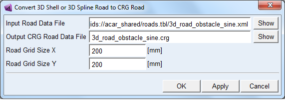
Converting 3D Shell or 3D Spline roads to OpenCRG roads
OpenCRG roads are normally faster to evaluate compared to 3D Shell or 3D Spline roads, and the solution speed of your simulation may be greatly improved by converting your 3D Shell or 3D Spline road to an OpenCRG road.
To convert a road:
From the Simulate menu, point to Full-Vehicle Analysis and select Road Conversion.
1. Select the existing 3D Shell or 3D Spline Road Data File that you want to convert.
2. Specify the New CRG Road Name of the OpenCrg road that will be created.
3. Specify the grid dimensions Road Grid Size X and Road Grid size Y of the OpenCRG road that will be created.
4. Select OK.
The road conversion will create 2 OpenCRG road files: a file with extension '.crg' containing the road height information for each grid point and a file with extension '.crgf' containing the road friction values for each grid point. For more information about the road friction, see Definition of Road Friction.
Notes: | ■If the road you want to convert contains small road obstacles, make sure the OpenCRG road grid is fine enough to capture such road obstacles. Keep in mind that using a finer road grid may increase the solution speed of your simulation. ■A too fine road grid may result in very large road data files. A warning is prompted for road files larger than 1 GB. ■The .crgf file will only be created if the input Road Data File contains friction values that differ from 1.0. If no .crgf file is available, the OpenCRG road uses the default value (1.0) for friction. |
3D Spline Road visualization
3D Spline roads can be fully visualized in Adams Car. Please note that the polyline and roughness obstacles are not visualized because their definition of the road height depends on mounted side of the tire on the vehicle.
In Adams View .rdf formatted files are visualized without the obstacles, .xml formatted files are not supported yet.
As explained before, a 3D Spline Road definition consists of two parts:
■Definition of the smooth road by a list of center line points (x,y,z), road width, banking and friction values.
■Definition of the obstacles to be superimposed on the smooth road.
When verifying your road by visualizing it in Adams, a few aspects of the spline properties and the 3D Road visualization can be of importance. These aspects are related to the distribution of the centerline points over you smooth road and the visualization of the obstacles on that road.
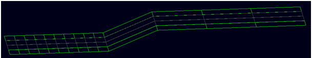
Distribution of centerline points
As the 3D Spline Road suggests, a spline method is used for the interpolation of positions in between the centerline points. The spline interpolation method will guarantee continuous changes of road height without any singularities and discontinuities. However the user should pay attention to the distribution of the road centerline points in order to avoid undesired changes of road height as illustrated in the example below:
Assume the following list of centerline points:
{ x y z width bank mu_left mu_right }
-10.0 0.0 0.0 10.0 0.0 1.0 1.0
-9.0 0.0 0.0 10.0 0.0 1.0 1.0
-8.0 0.0 0.0 10.0 0.0 1.0 1.0
-7.0 0.0 0.0 10.0 0.0 1.0 1.0
-6.0 0.0 0.0 10.0 0.0 1.0 1.0
-5.0 0.0 0.0 10.0 0.0 1.0 1.0
-4.0 0.0 0.0 10.0 0.0 1.0 1.0
-3.0 0.0 0.0 10.0 0.0 1.0 1.0
-2.0 0.0 0.0 10.0 0.0 1.0 1.0
-1.0 0.0 0.0 10.0 0.0 1.0 1.0
0.0 0.0 0.0 10.0 0.0 1.0 1.0
5.0 0.0 2.0 10.0 0.0 1.0 1.0
10.0 0.0 2.0 10.0 0.0 1.0 1.0
15.0 0.0 2.0 10.0 0.0 1.0 1.0
20.0 0.0 2.0 10.0 0.0 1.0 1.0
Adams Car (Adams 2011 and previous) will visualize the above defined road as shown below, because just the specific points given by the user are plotted:
However, when also interpolated points (in between the user defined points) are shown, the actual road experienced by a car will be different:
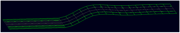
The spline method uses the relative large spacing in the second set of data points to avoid discontinuities and abrupt changes in road height.
With the current Adams version also the interpolated points can be visualized. By default one interpolated point in between two user defined points is shown. The user can adjust the number of interpolated points by setting the environment variable MSC_3D_SPLINE_INT_POINTS equal to the number of desired interpolated points.
Overlapping obstacles
Several types of obstacles can be selected to be superimposed on the smooth spline road. They can be positioned at any location and orientation, also on top of each other or they can have overlap.
Below an example of overlapping obstacles (positive and negative pothole) is depicted.
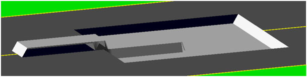
For the obstacle visualization is a grid approach is used, the default grid size (0.25 m) can be changed by setting the environment variable MSC_3D_SPLINE_GRD_SIZE equal to the desired grid size (in meter).
Note: | 3D drum roads in the 3D Spline Road format are not supported, 2D road offers a drum road. |