3D Enveloping Contact
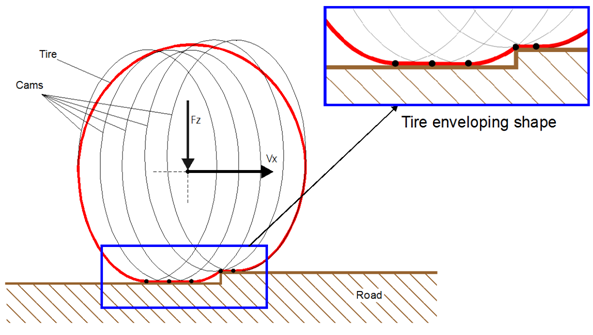
The 3D Enveloping Contact is using the semi-empirical 'tandem-cam' method for predicting the non-linear enveloping behavior of a tire when rolling over obstacles with a short wavelength (in the order of the tire contact patch length or smaller).
In the 'tandem cam' approach a series of connected elliptical cams are defined which shape corresponds to the outside tire contour in the tire contact patch zone. During the simulation the contact of each cam with the road is determined. Then the sum of the position and orientation of all cams results in an effective height, effective slope, effective road curvature and effective road camber for the tire model. The picture below shows the position of the cams for a tire rolling over a step obstacle.
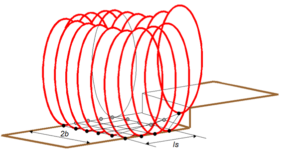
The 3D version of this method has been used, so that obstacles that are not symmetric with respect to the wheel will result in an effective road camber input for the tire model.
This has been illustrated in the picture below, in which the 3D tandem-cam is moving over an oblique cleat obstacle (nwidth = 6, nlength= 5), source [1].
The importance of using the 3D Enveloping contact can be shown by simulating a tire rolling over a cleat obstacle (0.01 x 0.01 m, rolling at 1 m/s) using the Adams Car tire test rig.
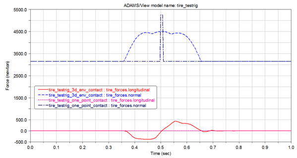
The tire with One-Point contact shows the shape of the obstacle more or less, while the tire with 3D Enveloping contact shows an increase of the normal load when the first point in contact patch starts to hit the obstacle. In addition the tire with 3D Enveloping contact will generate realistic longitudinal (resistance) force when rolling over.
The 3D Contact Enveloping Contact is supported by PAC2002, PAC-TIME, PAC89, PAC94, UA-Tire, Fiala, Air-Basic, Air-Enhanced and Air-TRR64 in combination with all Adams Tire road types, see also the Overview of the Adams Tire model features.
The number of required parameters for the 3D Enveloping Contact is limited. Basically the parameters determine:
■the tire-road contact patch dimension as a function of the tire deflection
Half the tire contact (patch) length a is defined as function of the unloaded tire radius R0 and the tire deflection ρz:
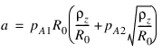
Note that the same relation is used in the non-linear (advanced) transient model for PAC2002, see Non linear transient model.
The equation used for half the tire contact (patch) width b is:
In which W0 is the nominal section width of the tire. These parameters can be derived by relative simple testing with a standing tire under different loading conditions.
■the dimension of the cams
Because the cams have an ellipsoid shape, their equation reads:
in which pae determines the length of the ellipse, pbe the height and pce is the ellipse exponent. The ellipse parameters can be derived from comparing the shape of the deflected tire with the ellipsoid shape.
■the number of cams in longitudinal and lateral direction
Verification with tests have shown that 5 cams along the length of tire contact patch and 6 across the width of tire contact patch results in best accuracy-performance ratio.
In longitudinal direction the cams are evenly distributed over tandem base length ls. The tandem based length ls depends on the contact length of the tire:

The figure below shows the position of the center of the cams at the contact patch (top view). The cams are positioned around the circumference of the 'squared' contact patch only because the cams at the intermediate points will cancel out each other.
The sum of the z positions (height) of the cams will result in the effective height w:
The effect forward slope  is calculated by:
is calculated by: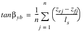
For the effective road camber  following equation is used:
following equation is used: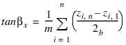
The road curvature is calculated with:

In which
■ls is the tandem base length
■b is half of the contact patch width
■z is the height of a specific cam center
■s is the travelled distance
For more details about the method and the extensive validation with tire measurement data is referred to the dissertation of Schmeitz [1].
Three additional weighting parameters (pW1, pW2 and pW3) may be used for a more accurate road slope  and effective height w:
and effective height w: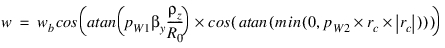

For using the 3D Enveloping Contact, the keyword 'CONTACT_MODEL' must be added in the [MODEL] section of the tire property file, specifying the:
CONTACT_MODEL = '3D_ENVELOPING'
If no further parameters are specified, the defaults parameters will used, otherwise the user can specify the parameters by adding a section [CONTACT_COEFFICIENTS] in the tire property file as shown in the example below (here with the default parameter values):
[CONTACT_COEFFICIENTS]
PA1 = 1.0 $Half contact length dependency on sqrt(defl/R0)
PA2 = 0.5 $Half contact length dependency on defl/R0
PB1 = 2.2 $Half contact width dependency on sqrt(defl/R0)
PB2 = 0.6 $Half contact width dependency on defl/R0
PB3 = -3.5 $Half contact width dependency on defl/R0*sqrt(defl/R0)
PAE = 1.05 $Half ellipse length/unloaded radius
PBE = 1.05 $Half ellipse height/unloaded radius
PCE = 1.8 $Ellipse exponent
PLS = 0.8 $Tandem base length factor
N_WIDTH = 6 $Number of cams across tire contact width
N_LENGTH = 5 $Number of cams along tire contact length
Because all 'length' parameters have been defined relative to the unloaded tire radius (they have no dimension), these default values will generate good starting points when not tire data is available.
Name | Name used in tire property file | Explanation |
|---|---|---|
pA1 | PA1 | Half contact length, main dependency on deflection |
pA2 | PA2 | Half contact length, square root dependency on deflection |
pB1 | PB1 | Half contact width, main dependency on deflection |
pB2 | PB2 | Half contact width, square root dependency on deflection |
pB3 | PB3 | Half contact width, dependency on deflection ^ 1.5 |
pae | PAE | Half ellipse length/unloaded radius |
pbe | PBE | Half ellipse height/unloaded radius |
pce | PCE | Ellipse exponent |
pls | PLS | Tandem base length factor |
nwidth | N_WIDTH | Number of cams across tire contact width |
nlength | N_LENGTH | Number of cams along tire contact length |
- | CONTACT_THREADS | Number of additional threads used for cam computations |
Specific requests for the 3D Enveloping Contact
Output | REQTYP Request | Component definitions |
|---|---|---|
Equivalent road input from the 3D Enveloping Contact | 18 | x = effective road height y = effective road angle z = effective road camber r1 = effective road curvature r2 = tire contact length r3 = tire contact width |
Example of an Adams Dataset section with this request:
! adams_view_name='tire.eff_road_inputs'
REQUEST/1
, CUNITS = "no_units", "length", "angle", "angle", "no_units", "angle"
, "length", "length"
, CNAMES = "", "eff_height", "eff_slope"
, "eff_camber", "", "eff_curvature", "contact_length", "contact_width"
, "", ""
, RESULTS_NAME = eff_road_inputs_envel_contact
, FUNCTION = USER(902, 18, 1)\
, ROUTINE = abgTire::req902
Using multi-threading for cam computations
To improve the solution speed of your simulation, cam computations of the 3D Enveloping Contact can be executed in parallel. Next to specifying parallelization at the Solver level (SMP, NTHREADS) in which Adams Solver may use a thread for each tire, additional threads can be specified for the cam computations of the 3D Enveloping Contact (if available).
For using multi-threading of the cam computations, the keyword 'CONTACT_THREADS' must be added to the [CONTACT_COEFFICIENTS] section of the tire property file, for example:
[CONTACT_COEFFICIENTS]
…
CONTACT_THREADS = 2
By default, CONTACT_THREADS is set to 0 which means that no additional threads are used for the cam computations.
References
1. A.J.C. Schmeitz, A Semi-Empirical Three-Dimensional Model of the Pneumatic Tyre Rolling over Arbitrarily Uneven Road Surfaces, PhD. Thesis, 2004, Delft University of Technology.
2. H.B. Pacejka, Tyre and Vehicle Dynamics, 2002, Butterworth-Heinemann, ISBN 0 7506 5141 5.