Using the Fiala Handling Force Model
This section of the help provides detailed technical reference material for defining tires on a mechanical system model using Adams Tire. It assumes that you know how to run Adams Car, or Adams Solver. It also assumes that you have a moderate level of tire-modeling proficiency.
The Fiala tire model is the standard tire model that comes with all Adams Tire modules. This chapter contains information for using the Fiala tire model:
Fiala Tire Assumptions
The background of the Fiala tire model is a physical tire model, where the carcass is modeled as a beam on an elastic foundation in the lateral direction. Elastic brush elements provide the contact between carcass and road. Under these assumptions, analytical expressions for the steady-state slip characteristics can be derived, which are the basis for the calculation of the longitudinal and lateral forces in Adams.
■Rectangular contact patch or footprint.
■Pressure distribution uniform across contact patch.
■Camber angle has no effect on tire forces.
Fiala Tire Inputs
The inputs to the Fiala tire model come from two sources:
■Input parameters from the tire property file (.tir), such as tire undeflected radius, that the tire references.
■Tire kinematic states, such as slip angle (α), which Adams Tire calculates.
The following table summarizes the input that the Fiala tire model uses to calculate force.
Input for Calculating Tire Forces
Quantity: | Description: | Use by Fiala: | Source: |
|---|---|---|---|
Mt | Mass of tire | ■Damping ■Vertical force (Fz) | - |
Alpha | Slip angle | Lateral force (Fy) | Tire kinematic state from Adams Solver |
Ss | Longitudinal slip ratio | Longitudinal force (Fx) | Tire kinematic state from Adams Solver |
pen | Penetration (tire deflection) | Vertical force (Fz) | Tire kinematic state from Adams Solver |
Vpen | d/dt (penetration) | Vertical force (Fz) | Tire kinematic state from Adams Solver |
Vertical_damping | Vertical damping coefficient | ■Damping ■Vertical force (Fz) | Tire property file (.tir) |
Vertical_stiffness | Vertical tire stiffness | Vertical force (Fz) | Tire property file (.tir) |
CSLIP | Partial derivative of longitudinal force (Fx) with respect to longitudinal slip ratio (S) at zero longitudinal slip | Longitudinal force (Fx) | Tire property file (.tir) |
CALPHA | Partial derivative of lateral force (Fy) with respect to slip angle (α) at zero slip angle | Lateral force (Fy) | Tire property file (.tir) |
UMIN | Coefficient of friction with full slip (slip ratio = 1) | Fx, Fy, Tz | Tire property file (.tir) |
UMAX | Coefficient of friction at zero slip | Fx, Fy, Tz | Tire property file (.tir) |
Rolling_resistance | Rolling resistance coefficient | Rolling resistance moment (Ty) | Tire property file (.tir) |
Tire Slip Quantities and Transient Tire Behavior
Definition of Tire Slip Quantities
Slip Quantities at combined cornering and braking/traction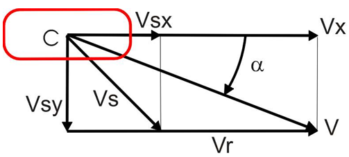
The longitudinal slip velocity Vsx in the SAE-axis system is defined using the longitudinal speed Vx, the wheel rotational velocity  , and the loaded rolling radius Re:
, and the loaded rolling radius Re: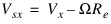
The lateral slip velocity is equal to the lateral speed in the contact point with respect to the road plane:

The practical slip quantities  (longitudinal slip) and
  (slip angle) are calculated with these slip velocities in the contact point:
(longitudinal slip) and (slip angle) are calculated with these slip velocities in the contact point:
and

The rolling speed Vr is determined using the effective rolling radius Re:

Note that for realistic tire forces the slip angle  is limited to 900 and the longitudinal slipSs (=
  ) in between -1 (locked wheel) and 1.
is limited to 900 and the longitudinal slipSs (= ) in between -1 (locked wheel) and 1.Contact Methods
The Fiala tire model supports all Adams Tire contact methods.
■One Point Follower Contact, used by default for 2D Road, 3D Spline Road, OpenCRG Road and RGR Road.
■3D Equivalent Volume Contact, used by default for 3D Shell Road.
■3D Enveloping Contact, can be used with all road types when the keyword CONTACT_MODEL = '3D_ENVELOPING' is specified in the [MODEL] section of the tire property file.
The contact method supplies the tire model with the (effective) road height and road plane for the tire deflection/penetration calculation.
Fiala Tire Force Evaluation
Types of force evaluation:
Normal Force of Road on Tire
The normal force of a road on a tire at the contact patch in the SAE coordinates (+Z downward) is always negative (directed upward). The normal force is:
Fz = min (0.0, {Fzk + Fzc})
where:
■Fzk is the normal force due to tire vertical stiffness
■Fzc is the normal force due to tire vertical damping
■Fzk = - vertical_stiffness × pen
■Fzc = - vertical_damping × Vpen
Instead of the linear vertical tire stiffness, also an arbitrary tire deflection - load curve can be defined in the tire property file in the section [DEFLECTION_LOAD_CURVE] (see the Fiala Tire Property File Format Example). If a section called [DEFLECTION_LOAD_CURVE] exists, the load deflection datap oints with a cubic spline for inter- and extrapolation are used for the calculation of the vertical force of the tire. Note that you must specify VERTICAL_STIFFNESS in the tire property file, but it does not play any role.
Longitudinal Force
The longitudinal force depends on the vertical force (Fz), the current coefficient of friction (U), the longitudinal slip ratio (Ss), and the slip angle (α). The current coefficient of friction depends on the static (Umax) and dynamic (Umin) friction coefficients and the comprehensive slip ratio ( ).
).
).Umax specifies the tire/road coefficient of friction at zero slip and represents the static friction coefficient. This is the y-intercept on the friction coefficient versus slip graph. Note that this value is an unobtainable maximum friction value, because there is always slip within a footprint. This value is used in conjunction with Umin to define a linear friction versus slip relation. Umax will normally be larger than Umin.
Umin specifies the tire/road coefficient of friction for the full slip case and represents the sliding friction coefficient. This is the friction coefficient at 100% slip, or pure sliding. This value is used in conjunction with Umax to define a linear friction versus slip relationship.
The comprehensive slip ( ):
):
):
The current value coefficient of friction (U):

Fiala defines a critical longitudinal slip (S_critical):
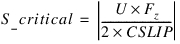
This is the value of longitudinal slip beyond which the tire is sliding.
Case 1. Elastic Deformation State: |Ss| < S_critical
Fx = -CSLIP × Ss
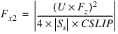
Case 2. Complete Sliding State: |Ss| > S_critical
Fx = -sign(Ss)(Fx1- Fx2)
where:

Lateral Force
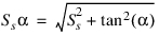
Like the longitudinal force, the lateral force depends on the vertical force (Fz) and the current coefficient of friction (U). And similar to the longitudinal force calculation, Fiala defines a critical lateral slip  :
:
: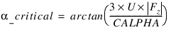
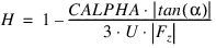
The lateral force peaks at a value equal to U × |Fz| when the slip angle (α) equals the critical slip angle ( ).
).
).Case 1. Elastic Deformation State: 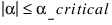
Fy = - U × |Fz|× (1-H3) × sign(α)
where:

Case 2. Sliding State: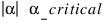
Fy = -U|Fz|sign(α)
Rolling Resistance Moment
When the tire is rolling forward: Ty = -rolling_resistance * Fz
When the tire is rolling backward: Ty = rolling_resistance * Fz
Aligning Moment
Case 1. Elastic Deformation State: 
Mz = U × |Fz| × WIDTH × (1-H) × H3 × sign(α)
where:
Case 2. Complete Sliding State: 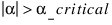
Mz= 0.0
Smoothing
Adams Tire can smooth initial transients in the tire force over the first 0.1 seconds of simulation. The longitudinal force, lateral force, and aligning torque are multiplied by a cubic step function of time. (See STEP function in the Adams Solver online help).
Longitudinal Force FLon = S*FLon
Lateral Force FLat = S*FLat
Aligning Torque Mz = S*Mz
The USE_MODE parameter in the tire property file allows you to switch smoothing on or off:
■USE_MODE = 1, smoothing is off
■USE_MODE = 2, smoothing is on
Transient Behavior in the Fiala Tire Model
In the upper sections described force calculations are valid for the 'so-called' steady-state tire response, in other words tire dynamics is not taken into account. However, in general, the tire will be exposed to changes of input in terms of vertical load and longitudinal and lateral slip continuously.
For estimating transient tire behavior, a linear transient model is used as described in [1].
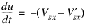
In the linear transient model the tire contact point S' is suspended to the wheel-rim plane with a longitudinal and lateral spring, with respectively stiffness's CFx and CFy, see Reference. In the figure below a top view of the tire with the single contact point S' and the longitudinal (u) and lateral (v) carcass deflections is shown.
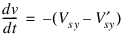
The contact point may move with respect to the wheel-rim plane and road. Movements relative to the road will result in tire-road interaction forces. Differences in slip velocities at point S and point S' will result in the tire carcass to deflect. The change of the longitudinal deflection u can be defined as:
and the lateral deflection v as:
For small values of slip the side force Fy can be calculated using the cornering stiffness CFα as follows:
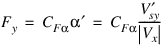
While the lateral force on the carcass reads:

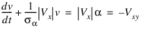
When introducing the lateral relaxation length σα as:

the differential equation for the lateral deflection can be written as follows:
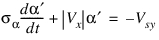
For linear small slip we can define the practical slip quantity α' as:
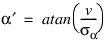
With α' the equation for the lateral deflection becomes:
Similar the differential equation for longitudinal direction with the longitudinal relaxation length σκ can be derived:
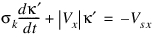
with the practical slip quantity 

These practical slip quantities  and
and  are used instead of the usual κ and α definitions for steady-state tire behavior.
and are used instead of the usual κ and α definitions for steady-state tire behavior.The longitudinal and lateral relaxation length are read from the tire property file, see Fiala Tire Property File Format Example.
Note that in transient mode the tire model is able to deal with zero speed (stand-still), because this linear transient model works with tire deflections instead of slip velocities.
The effective lateral compliance of the tire at stand-still in transient mode is:

And similar in longitudinal direction the compliance is:

Reference
1. H.B. Pacejka, Tyre and Vehicle Dynamics, 2002, Butterworth-Heinemann, ISBN 0 7506 5141.
Fiala Tire Carcass Shape
Using Fiala tire, you can optionally supply a tire carcass cross-sectional shape in the tire property file in the [SHAPE] block. The 3D-durability, tire-to-road contact algorithm uses this information when calculating the tire-to-road volume of interference. To learn more about this topic, see Applying the Tire Carcass Shape. If you omit the [SHAPE] block from a tire property file, the tire carcass cross-section defaults to the rectangle that the tire radius and width define.
You specify the tire carcass shape by entering points in fractions of the tire radius and width. Because Adams Tire assumes that the tire cross-section is symmetrical about the wheel plane, you only specify points for half the width of the tire. The following apply:
■For width, a value of zero (0) lies in the wheel center plane.
■For width, a value of one (1) lies in the plane of the side wall.
■For radius, a value of one (1) lies on the tread.
For example, suppose your tire has a radius of 300 mm and a width of 185 mm and that the tread is joined to the side wall with a fillet of 12.5 mm radius. The tread then begins to curve to meet the side wall at +/- 80 mm from the wheel center plane. If you define the shape table using six points with four points along the fillet, the resulting table might look like the shape block that is at the end of the following property format example.
Fiala Tire Property File Format Example
$---------------------------------------------------------MDI_HEADER
[MDI_HEADER]
FILE_TYPE = 'tir'
FILE_VERSION = 2.0
FILE_FORMAT = 'ASCII'
(COMMENTS)
{comment_string}
'Tire - XXXXXX'
'Pressure - XXXXXX'
'Test Date - XXXXXX'
'Test tire'
'New File Format v2.1'
$--------------------------------------------------------------units
[UNITS]
LENGTH = 'mm'
FORCE = 'newton'
ANGLE = 'degree'
MASS = 'kg'
TIME = 'sec'
$--------------------------------------------------------------model
[MODEL]
! use mode 1 2 11 12
! --------------------------------------------
! smoothing X X
! transient X X
!
PROPERTY_FILE_FORMAT = 'FIALA'
USE_MODE = 2.0
$----------------------------------------------------------dimension
[DIMENSION]
UNLOADED_RADIUS = 309.9
WIDTH = 235.0
ASPECT_RATIO = 0.45
$----------------------------------------------------------parameter
[PARAMETER]
VERTICAL_STIFFNESS = 310.0
VERTICAL_DAMPING = 3.1
ROLLING_RESISTANCE = 0.0
CSLIP = 1000.0
CALPHA = 800.0
UMIN = 0.9
UMAX = 1.0
RELAX_LENGTH_X = 0.05
RELAX_LENGTH_Y = 0.15
$--------------------------------------------------------------shape
[SHAPE]
{radial width}
1.0 0.0
1.0 0.2
1.0 0.4
1.0 0.5
1.0 0.6
1.0 0.7
1.0 0.8
1.0 0.85
1.0 0.9
0.9 1.0
$------------------------------------------------load_curve
$ Maximum of 100 points (optional)
[DEFLECTION_LOAD_CURVE]
{pen fz}
0 0.0
1 212.0
2 428.0
3 648.0
5 1100.0
10 2300.0
20 5000.0
30 8100.0