Adams Tire 3D Shell Road Model
The 3D Shell Road utilizes a three-dimensional tire-to-road contact model (3D Equivalent Volume Contact) that computes the volume of intersection between a road and tire. From the intersection volume the method computes an equivalent plane's effective road normal, penetration, tire to road contact point, and effective road friction. The road is modeled as a set of discrete triangular patches, the tire as a set of cylinders. This model lets you simulate a vehicle that is hitting a curb or pothole, or moving on rough, irregular road surfaces.
The 3D Shell Road uses data from both the tire property and road property files. The road model uses these blocks from the tire property file:
■Units
■Unloaded_Radius
■Width
■Shape
From the road property file it uses these blocks:
■Title
■Units
■Model
■Offset
■Nodes
■Element
Applying the Tire Carcass Shape
This section discusses how the three-dimensional shell road applies the tire carcass shape, which is defined in the tire property file (for more information on defining shape in the tire property file, see Fiala Tire Carcass Shape). The contact algorithm interpolates the tire carcass shape to a given number of equally spaced points.
You define the tire carcass shape as a set of points in the shape table ([SHAPE]) of the tire property file. Adams Tire assumes that tire carcass shape is symmetrical over the center line of the tire. Therefore, you need to enter shape points for only half of the tire width. If the tire carcass shape is not defined, Adams Tire defines it as a rectangular shape based on the radius and width of the tire.
You define carcass shape in terms of relative values (scales). Absolute coordinate values for the shape are computed by multiplying relative values with the unloaded radius and half-width of the tire. The relative width of the tire must be given in ascending order from 0.0 to 1.0, where the value 0.0 corresponds to the center line of the tire. The maximum number of shape points is 10.
Tire Carcass Defined Using Given Shape and Interpolated Values
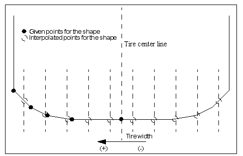
The 3D Equivalent Volume Contact uses a series of 2d circle contacts to a 3d road. The tire width is divided into a number of equal sections. The number of sections is 2x the number of points you give for the tire shape. If no shape is present, the width of the tire is divided into 10 sections.
Given the user's tire shape the tire computes the un-deformed radius at the center of each section, this defines the circle that is used in the road contact for a given section. The intersecting area of the circle and road is computed then multiplied by the section width to get the intersecting volume and center of the volume. The intersecting volume is converted to an equivalent flat road response.
Road Property File
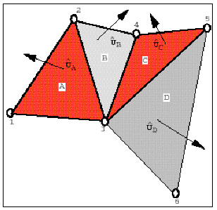
The contact algorithm works from a triangle tessellated road representation. The figure below depicts a road surface formed by six nodes numbered 1 through 6. The six nodes together form four triangular patch elements denoted as A, B, C, and D. The unit outward normal for each triangular patch is shown for the sake of clarity. Much like finite-element mesh convention, you define a road by first specifying the coordinates of each node in the road-reference-marker axis system. Subsequently, you specify the three nodes that form each triangular patch. For each triangular patch, you can specify a coefficient of friction.
Road Representation in Adams Tire
Defining the 3D Shell Road Surface
You use a road property file to define the three-dimensional road surface. The road property file consists of five data blocks:
■Header
■Units
■Model
■Nodes
■Elements
These blocks of data can appear in any order in the file, and keywords can appear in any order within the block to which they belong.
The road property file can contain more data than what the 3D Shell Road currently requires. The 3D Shell Road searches for the blocks and keywords it needs and disregards any additional information in the file. Any line that is not recognized as input data is treated as a comment, and therefore skipped. Therefore, you can use almost any character to begin a comment line, but we recommend that you use $'s, !'s, or #'s to avoid confusion. Avoid using comment lines beginning with a square bracket ( [ ), or lines that could interfere with keywords.
Tables must always appear as one set of data. No comment or empty lines are allowed between lines. Tables must always have a header line beginning with a brace, ( { ).
A keyword and its value are separated by an equal sign (=). You must enter strings within single (' ') or double (" ") quotes.
Examples of Blocks:
Units Block
Block header:[UNITS]
Keywords: Allowed values:
LENGTH = {'meter', 'mm', 'cm', 'km', 'inch', 'mile'}
ANGLE = {'rad', 'radian', 'deg', 'degree'}
Model Block
The method keyword in the block determines the road contact algorithm Adams Tire uses. You must set method='3D' to instruct Adams Tire to use the 3D Shell Road algorithm.
Block header: [MODEL]
Keywords: Allowed values:
METHOD = {'3D'}
Road Repositioning
The position and orientation of the road can be changed by defining the reference system in the optional [REFSYS] block:
Keyword: | Description: |
|---|---|
OFFSET | Three values, respectively the translational offset value in longitudinal direction, the translational offset value in lateral direction and the translational offset value in vertical direction, all default 0. |
ROTATION_ANGLE_XY_PLANE | The rotational offset around the Z-axis, default 0. |
In the TeimOrbit formatted road property file, this section will list as follows:
$-------------------------------------------------------------refsys
[REFSYS]
OFFSET = 1.0 0.0 0.3
ROTATION_ANGLE_XY_PLANE = 25.0
Nodes Block
Block header: [NODES]
Keywords: Allowed values:
NUMBER_OF_NODES = <an integer number>
Tabular data:
{ node x_value y_value z_value }
1 <a real number (X)> <a real number (Y)> <a real number (Z)>
2 <a real number (X)> <a real number (Y)> <a real number (Z)>
...
<an integer number> <a real number (X)> <a real number (Y)> <a real number (Z)>
Elements Block
Block header: [ELEMENTS]
Keywords: Allowed values:
NUMBER_OF_ELEMENTS = <an integer number>
Tabular data:
{ node_1 node_2 node_3 mu }
<an integer number> <an integer number> <an integer number> <a real number>
<an integer number> <an integer number> <an integer number> <a real number>
...
<an integer number> <an integer number> <an integer number> <a real number>
Road Normal calculation and Road Boundaries
The road normal calculation of 3D Shell road is based on the road geometry of the road.
When a wheel passes a road boundary (kerbside), the wheel-road contact will be lost and thus the vehicle will start to drop down. The solver may encounter stability problems in some cases and start reducing step size or even run into stability problems. By setting the environment variable MSC_ADAMS_TIRE_ROAD_EDGE_STOP solver will abort the simulation if a wheel passes a road boundary:
MSC_ADAMS_TIRE_ROAD_EDGE_STOP=YES
Note: | 3D drum roads in the 3D Shell Road format are not supported, 2D road offers a drum road. |