Defining Tires
If you use Adams Car, typically the models you work with will already include tires (for example, the statements necessary to invoke Adams Tire). Therefore, you do not need to add tires to your model. If you work with Adams View, however, you will need to define the tires, and for Adams Solver, add statements to your Adams model using Adams View or a text editor. Learn how to work with:
Defining Tires in Adams Car
Adams Car includes a wheel-tire subsystem and template that you can use in any full-vehicle assembly. The wheel-tire subsystem includes all the elements necessary to start Adams Tire.
To create and modify a tire in the Adams Car Template builder
In the Adams Car Template builder, you can define and modify a tire by clicking at Build → Wheel → New/Modify:
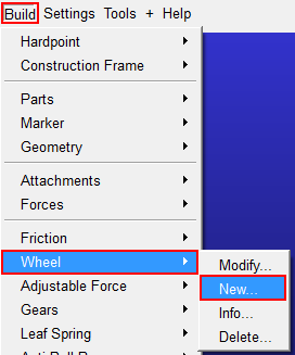
The following dialog box will appear:
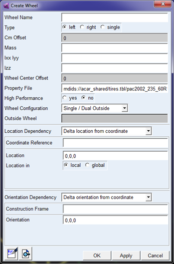
The Cm Offset is the lateral offset of the wheel with respect to the location (wheel mount point).
The Mass and Inertia should consider the total mass of the rim and tire, see section Defining Wheel Inertia.
In case of the use of a PAC2002 tire model, the High Performance switch will appear, which will cause the model to run faster by changing some model options, see section High Performance switch in Adams Car.
The wheel configuration offers to define dual tires, for example in case of a dual axle for a truck. Because the in- and outside wheel need to be fixed to each other, a reference to the outside wheel needs to be made when defining the inside wheel.
The lower part of the dialog box allows you to define the location and orientation of the wheel using the common Adams methods.
To modify tires in a subsystem:
When doing a right mouse click on a tire in the graphical display of the model, or clicking on a 'ac-tire' instance in the Database navigator, you can modify the properties of the wheel:
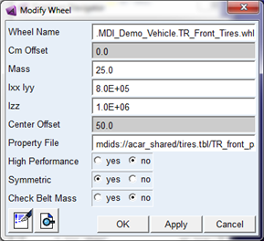
The mass and inertia should consider the total mass of the rim and tire, see section Defining Wheel Inertia. Automatically the mass and inertia of the wheel part will be corrected for the mass and inertia of the tire belt in case FTire or PAC2002 with belt dynamics is used.
When accepting the 'Check Belt Mass' option, the mass and inertia values will be verified with the correction of the belt mass and inertia, if applicable.
In case of the use of a PAC2002 tire model, the High Performance switch will appear, which will cause the model to run faster by changing some model options, see section High Performance switch in Adams Car.
Defining Tires in Adams Solver
If you use Adams Solver, you must add a set of statements to your Adams model for each tire as described in the table, Statements Needed for Adding Tires to Your Model. Once you have added these statements to your model, you change the tire or road property file by entering new file names in the STRING statements holding the file names. You can do this in your Adams Solver dataset files (.adm) or from an Adams Solver command file (.acf) using a STRING command. In an .acf file, the STRING command must appear before any simulation commands. For example:
test_rig.adm
mytest
STRING/99, STRING=/usr/mdi/solver/atire/tires.tbl/mdi_fiala01.tir
SIMULATE/STATIC
SIMULATE/DYNAMIC, DURATION=1.0,STEPS=50
STOP
Learn more:
Statements Needed for Defining Tires
For each tire you want to add to your model, you must create a set of statements in your model. This can be done using the dialog box in Adams View (see Defining Tires in Adams View) or manually using a text editor. For a car with four tires, you need four sets of statements. The table below describes the sets of statements which consists of a GFORCE, GSE and related variables for each tire. The table, MARKER Locations and Orientations, describes how to locate and orient the three MARKERs.
Note: | This example does not consider the use of PAC2002 with the belt dynamics feature, in that case a belt part and additional GFORCE is added. |
A description of the outdated set of statements based on the GFORCE - DIFF method can be found in the appendix section.
Statements Needed for Adding Tires to Your Model
Statement types: | Purpose in dataset: |
|---|---|
MARKER (4) | ■Wheel center marker -(tire_i marker) Identifies the wheel part, the wheel center location and orientation, and the location for applying tire force movements. This marker is used as the GFORCE I and VARIABLE I marker. The Z-axis is defined as the spin axis. ■Road floating marker - (wheel_tire_tire_jf marker) Identifies the road part to the GFORCE for applying reaction forces. This marker is used as the GFORCE JFLOAT marker. ■Road reference marker - (road_ref marker) Identifies the origin and orientation of the road. This marker is used as the GFORCE RM and VARIABLE RM marker. You must locate and orient the MARKER statements as described in MARKER Locations and Orientations. |
PART(1) | Wheel tire part |
GFORCE (1) | Applies the tire forces and moments coming from the tire model to the wheel part between the Tire I marker and the Road floating marker. Tire model and road model are specified in the property files. More information about the parameters in the USER function of the GFORCE is given in the example below. |
GSE (1) | The GSE is used to calculate the tire states only, so the number of outputs (NO) is set to zero. The tire states are passed to the tire model via the STI Tire interface. The number of states (NS) is equal to the number of tire states plus one. This extra state, defined by the last variable of the GSE input array, is only used in Adams Car for steady state analysis and is set to zero in the example below. So, if your tire model has 3 tire states, NS should be set to 3+1=4 and the second number of the wheel tire input array holding the number of tire states should be set to 3. |
VARIABLE (17) | The variables define the tire motion states and are passed to the GSE via the Input array U. ■Time ■3 translational displacements x, y and z of the wheel center marker with respect to road reference marker ■3 translational velocities vx, vy and vz of the wheel center marker with respect to the road reference marker ■3 rotational velocities wx, wy and wz of the wheel center marker with respect to the road reference marker ■6 unit vector components defining the cosines matrix of the wheel with respect to the road reference marker ■Longitudinal slip during steady-state analysis. This variable is only used in Adams Car simulations and is set to zero if the model does not contain functionality for such an event. |
STRING (5) | Identify the property files and other miscellaneous information. ■Tire property file ■Road property file ■Role ■Tire contact ■Simulation type |
ARRAY (5) | The arrays contain GSE, tire and user input information. ■GSE tire input array U ■GSE tire output array Y ■GSE tire state array X ■Wheel tire input array (holds all tire input information) ■Wheel tire scales array (holds tire forces and moment scaling factors) ■Wheel tire user array (used for user-written tire models to pass information from the ADAMS dataset to the tire model) More detailed information about the tire and user input arrays can be found in the example below. |
REQUEST (Up to 11) | Output tire kinematics and forces (longitudinal slip, slip angle, camber angle, contact patch forces, and moments). For more information, see Performing Simulations and Viewing Results. |
MARKER Locations and Orientations
Marker statements required in dataset: | Location and orientation: |
|---|---|
Wheel center marker (tire_i) | Because the tire applies forces to the wheel center marker, you must define the wheel center so that it belongs to the wheel part and is located at the wheel center. You orient the wheel center as follows: ■x-axis lies in the wheel plane and points in the forward direction of the wheel. ■y-axis is defined as the spin-axis of the wheel. ■z-axis lies in the wheel plane and is orthogonal to the x-axis and y-axis. |
Road floating marker (wheel_tire_tire_jf) | The tire applies the reaction forces to the road floating marker. The road floating marker must belong to the road part, usually ground, and must be defined as FLOATING. Because the marker floats, you do not enter a location or orientation. |
Road reference marker (road_ref) | The road reference marker gives the location and orientation of the road. You define the road reference marker so that it belongs to the road part, usually ground. In addition, the road reference marker's z-axis must be directed upward, meaning the z-axis is parallel to, but points in the opposite direction of, the gravity vector. Locations of the points on the road contained in the road property file are given relative to this marker. Generally, the road reference marker should be located on the road surface and below the wheel center by approximately the static loaded radius of the tire. |
Example Dataset
This section gives you an example dataset that includes a complete set of statements for a single tire. The example is based on the following assumptions:
■PART/1 is ground
■The orientations assume that the ground part's x-axis points from the rear to the front of the vehicle, the y-axis points from the right towards the left side of the vehicle, and the z-axis points upward.
■Following units are used: Force = Newton, Mass = Kilogram, Length = Millimeter, Time = Second.
!
! adams_view_name='road_ref_1'
MARKER/2, PART = 1
!
! adams_view_name='wheel_tire_tire_jf_1'
MARKER/3, PART = 1, FLOATING
!!
----------------------------------- Part ----------------------------
!
! adams_view_name='wheel_tire.wheel_part'
PART/2, QG = 0, 0, 300, REULER = 0D, 90D, 0D, MASS = 20, CM = 4
, IP = 50000, 50000, 10000, VM = 4, WM = 4, VX = 20, WZ = -4020D
!
! adams_view_name='tire_i'
MARKER/1, PART = 2, REULER = 180D, 90D, 180D
!
! adams_view_name='wheel_cm'
MARKER/4, PART = 2
Comments: The wheel_cm marker defines the spin axis of the wheel_tire.
Both location and orientation are defined by the wheel_tire.wheel_part.
!
!--------------------------------- FORCES ---------------------------
!
! adams_view_name='wheel_tire.force'
GFORCE/1, I = 1, JFLOAT = 3, RM = 2, FUNCTION = USER(908, 1, 4)\
, ROUTINE = abgTire::gfo908
Comments: The USER function of the GFORCE is defined as follows:
- 908 - refers to the STI Tire interface based on the GFORCE/GSESUB method.
- 1 - stands for the Tire GFORCE statement ID and is used to distinguish between the different tires.
- 4 - refers to the wheel tire input array.
!---------------------------- DATA STRUCTURES -----------------------
!
! adams_view_name='wheel_tire.tpf_file'
STRING/1, STRING =pac2002_175_70R13.tir
!
! adams_view_name='wheel_tire.rpf_file'
STRING/2, STRING =mdi_2d_flat.rdf
!
! adams_view_name='wheel_tire.role'
STRING/3, STRING =none
!
! adams_view_name='wheel_tire.tire_contact'
STRING/4, STRING =handling
Comments: This tire_contact is obsolete for handling/durability. It is used as a flag for moving roads which is beyond the scope of this article.
!
! adams_view_name='wheel_tire.simulation_type'
STRING/5, STRING =none
Comments: The simulation type obsolete for the GFORCE/GSESUB Tire interface
!
! time input to the tire
! adams_view_name='wheel_tire.u_time'
! adams_view_name='wheel_tire.u_time'
VARIABLE/1, FUNCTION = TIME
!
! tire x displacement
! adams_view_name='wheel_tire.u_dx'
! adams_view_name='wheel_tire.u_dx'
VARIABLE/2, FUNCTION = dx(1,2,2)
!
! tire y displacement
! adams_view_name='wheel_tire.u_dy'
! adams_view_name='wheel_tire.u_dy'
VARIABLE/3, FUNCTION = dy(1,2,2)
!
! tire x displacement
! adams_view_name='wheel_tire.u_dz'
! adams_view_name='wheel_tire.u_dz'
VARIABLE/4, FUNCTION = dz(1,2,2)
!
! tire rim x dot road x
! adams_view_name='wheel_tire.u_x_dot_x'
! adams_view_name='wheel_tire.u_x_dot_x'
VARIABLE/5, IC = 1, FUNCTION = USER(907, 1, 2, 2, 1, 1)\
, ROUTINE = abgFDM::var907
Comments: The USER functions of the VARIABLES 5 to 10 are defined as follows:
- 907 - Refers to the routine that return the Unit Vector Components
- 1 - id I marker
- 2 - id J marker
- 2 - id RM marker
- 1 - direction (1,2 or 3 returns the direction cosines of the xaxis, y-axis or z-axis respectively of marker I in the coordinate system of marker J)
- 1 - component (element of the direction cosines as specified by the direction)
- 1 - id I marker
- 2 - id J marker
- 2 - id RM marker
- 1 - direction (1,2 or 3 returns the direction cosines of the xaxis, y-axis or z-axis respectively of marker I in the coordinate system of marker J)
- 1 - component (element of the direction cosines as specified by the direction)
!
! tire rim x dot road y
! adams_view_name='wheel_tire.u_x_dot_y'
! adams_view_name='wheel_tire.u_x_dot_y'
VARIABLE/6, IC = 0, FUNCTION = USER(907, 1, 2, 2, 1, 2)\
, ROUTINE = abgFDM::var907
!
! tire rim x dot road z
! adams_view_name='wheel_tire.u_x_dot_z'
! adams_view_name='wheel_tire.u_x_dot_z'
VARIABLE/7, IC = 0, FUNCTION = USER(907, 1, 2, 2, 1, 3)\
, ROUTINE = abgFDM::var907
!
! tire rim y dot road x
! adams_view_name='wheel_tire.u_y_dot_x'
! adams_view_name='wheel_tire.u_y_dot_x'
VARIABLE/8, IC = 0, FUNCTION = USER(907, 1, 2, 2, 2, 1)\
, ROUTINE = abgFDM::var907
!
! tire rim y dot road y
! adams_view_name='wheel_tire.u_y_dot_y'
! adams_view_name='wheel_tire.u_y_dot_y'
VARIABLE/9, IC = 1, FUNCTION = USER(907, 1, 2, 2, 2, 2)\
, ROUTINE = abgFDM::var907
!
! tire rim y dot road z
! adams_view_name='wheel_tire.u_y_dot_z'
! adams_view_name='wheel_tire.u_y_dot_z'
VARIABLE/10, IC = 0, FUNCTION = USER(907, 1, 2, 2, 2, 3)\
, ROUTINE = abgFDM::var907
!
! tire x velocity
! adams_view_name='wheel_tire.u_vx'
! adams_view_name='wheel_tire.u_vx'
VARIABLE/11, IC = 20, FUNCTION = USER(906, 1, 1, 2, 2)\
, ROUTINE = abgTire::var906
Comments: The USER functions of the VARIABLES 11 to 16 are defined as
follows:
- 906 - Refers to the routine that return tire velocities
- 1 - component (vx=1, vy=2, vz=3, wx=4, wy=5, wz=6)
- 1 - component (vx=1, vy=2, vz=3, wx=4, wy=5, wz=6)
- 1 - id I marker
- 2 - id J marker
- 2 - id RM marker
!
! tire y velocity
! adams_view_name='wheel_tire.u_vy'
! adams_view_name='wheel_tire.u_vy'
VARIABLE/12, IC = 0, FUNCTION = USER(906, 2, 1, 2, 2)\
, ROUTINE = abgTire::var906
!
! tire z velocity
! adams_view_name='wheel_tire.u_vz'
! adams_view_name='wheel_tire.u_vz'
VARIABLE/13, IC = 0, FUNCTION = USER(906, 3, 1, 2, 2)\
, ROUTINE = abgTire::var906
!
! tire wx velocity
! adams_view_name='wheel_tire.u_wx'
! adams_view_name='wheel_tire.u_wx'
VARIABLE/14, FUNCTION = USER(906, 4, 1, 2, 2)\
, ROUTINE = abgTire::var906
!
! tire wy velocity
! adams_view_name='wheel_tire.u_wy'
! adams_view_name='wheel_tire.u_wy'
VARIABLE/15, IC = 70.16223593, FUNCTION = USER(906, 5, 1, 2, 2)\
, ROUTINE = abgTire::var906
!
! tire wz velocity
! adams_view_name='wheel_tire.u_wz'
! adams_view_name='wheel_tire.u_wz'
VARIABLE/16, FUNCTION = USER(906, 6, 1, 2, 2)\
, ROUTINE = abgTire::var906
!
! tire steady state longitudinal slip
! adams_view_name='wheel_tire.u_ss_lon_slip'
! adams_view_name='wheel_tire.u_ss_lon_slip'
VARIABLE/17, IC = 0, FUNCTION = 0.0
!
! Tire input array
! adams_view_name='wheel_tire.tire_input_array'
! adams_view_name='wheel_tire.tire_input_array'
ARRAY/1, U, SIZE = 17, VARIABLES = 1, 2, 3, 4, 5, 6, 7, 8, 9
, 10, 11, 12, 13, 14, 15, 16, 17
!
! Tire output array (forces and moments)
! adams_view_name='wheel_tire.tire_output_array'
! adams_view_name='wheel_tire.tire_output_array'
ARRAY/2, Y
!
! Tire states array
! adams_view_name='wheel_tire.tire_state_array'
! adams_view_name='wheel_tire.tire_state_array'
ARRAY/3, X
!
! Input array for tire gfosub
! p1 : id of ARRAY holding tire states
! p2 : number of tire states
! p3 : Side (0=left, 1=right)
! p4 : Minor Role STRING id
! p5 : Tire Property File STRING id
! p6 : Simulation Type STRING id
! p7 : Road Property file STRING id
! p8 : Contact Type STRING id
! p9 : Rig Radius (Rigid Wheel)
! p10: Steady State DIFF id
! p11: ISWITCH (0=static tire, 1=dynamic tire)
! p12: id of ARRAY holding scaling and drift factors
! p13: id of ARRAY holding user parameters
! adams_view_name='wheel_tire.input_array'
ARRAY/4, IC, SIZE = 13, NUMBERS = 3, 2, 0, 3, 1, 5, 2, 4, 290
, 0, 1, 5, 6
!
!
! Scaling array for tire
! p1 : Unloaded Radius Offset
! p2 : Lateral Force Scale Factor
! p3 : Overturning Moment Scale Factor
! p4 : Aligning Torque Scale Factor
! p5 : Plysteer Force
! p6 : Conicity Force
! p7 : Plysteer Torque
! p8 : Conicity Torque
! adams_view_name='wheel_tire.scales_array'
ARRAY/5, IC, SIZE = 8, NUMBERS = 0, 1, 1, 1, 0, 0, 0, 0
!
! adams_view_name='wheel_tire.user_array'
ARRAY/6, IC, SIZE = 10, NUMBERS = 1, 2, 3, 4, 5, 6, 7, 8, 9, 10
!
!--------------------------------- EQUATIONS -------------------------
!
! adams_view_name='wheel_tire.tire_gse'
GSE/1, NS = 3, NO = 0, X = 3, XXFLAG = USER, U = 1, Y = 2
, XUFLAG = USER, YUFLAG = USER, YXFLAG = USER
, FUNCTION = USER(908, 1, 4)\
, ROUTINE = abgTire::gse908, abgTire::sti_gsexx908
, abgTire::sti_gsexu908, abgTire::sti_gseyx908, abgTire::sti_gseyu908
Comments: The USER function of the GSE is defined as follows:
- 908 - refers to the STI Tire interface based on the GFORCE/GSESUB method.
- 1 - stands for the Tire GFORCE statement ID and is used as a reference to the tire.
- 4 - refers to the wheel_tire.input_array holding tire input information.
- 1 - stands for the Tire GFORCE statement ID and is used as a reference to the tire.
- 4 - refers to the wheel_tire.input_array holding tire input information.
Note 1: The number of states NS has to be equal to the number of tire states as specified in wheel_tire.input_array plus 1, so 2+1=3.
Note 2: The number of outputs (NO) is set to 0 as the tire forces and moments are obtained from the GFORCE statement.
!----------------------------- OUTPUT ---------------------------
!
! adams_view_name='wheel_tire.radius_request'
REQUEST/1, FUNCTION = USER(902, 1, 1)\ ROUTINE = abgTire::req902
Comments: The USER functions of the REQUEST 1 to 3 are defined follows:
- 902 - Refers to the tire request subroutine
- 1 - Specifies the information output to the request file (1 = tire rolling states, 2 = tire kinematic properties in TYDEX-W axis (ISO) system, 3 = tire contact patch forces in TYDEX-W axis (ISO) system)
- 1 - Tire GFORCE statement ID
! adams_view_name='wheel_tire.kinematics_request'
- 1 - Specifies the information output to the request file (1 = tire rolling states, 2 = tire kinematic properties in TYDEX-W axis (ISO) system, 3 = tire contact patch forces in TYDEX-W axis (ISO) system)
- 1 - Tire GFORCE statement ID
! adams_view_name='wheel_tire.kinematics_request'
REQUEST/2, FUNCTION = USER(902, 2, 1)\ ROUTINE = abgTire::req902
!
! adams_view_name='wheel_tire.forces_request'
REQUEST/3, FUNCTION = USER(902, 3, 1)\ ROUTINE = abgTire::req902
Defining Tires in Adams View
Adams View provides a dialog box that introduces a tire-wheel assembly in your model. You can also use the dialog box to create a road.
Creating a Tire-Wheel Assembly
To create a tire-wheel assembly in Adams View:
1. Do one of the following:
■From the ribbon menu, click Forces.
■From the Special Forces container, select the Tire  tool.
tool.
tool.Classic interface do the following:
■From the Build menu, point to Forces, and then select Special Force: Tire.
The Create Wheel and Tire dialog box appears with options that allow you to introduce the wheel inertia, tire property file, and side of the vehicle.
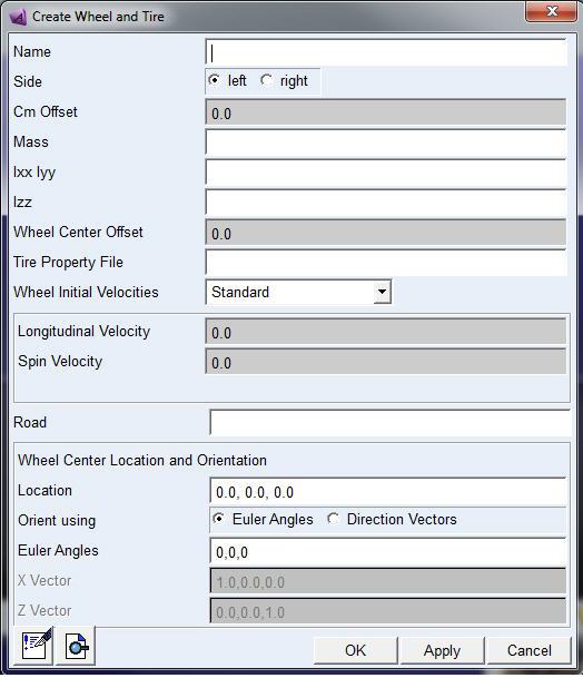
2. Enter the values as desired to define the tire, and then select OK. Learn more with Create/Modify Wheel and Tire dialog box help.
Creating a Road
If your model includes tires, you must specify a road because each tire must reference a road. The road determines the surface friction, bumps, and other inputs to tires.
To create the road:
1. Display the Create Wheel and Tire dialog box as explained in step 1 above.
2. Right-click the Road text box, point to vpg_road, and then select Create.
The Create Road dialog box appears.
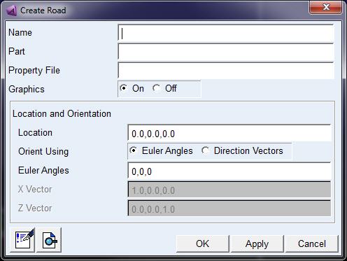
3. Enter the values as desired, and then select OK. Learn more about the values with Create/Modify Road dialog box help..
Note: | This dialog box generates a tire interface based on the general-state equation subroutine. A more simple interface is shown in Defining Tires Using Adams Solver. |
Defining Wheel Inertia
With Adams version 2013.2 and later, the required input for the mass and inertia of the tire / wheel is consistent for all models (Adams Tire models and FTire) across all Adams products:
The supplied mass and inertia must account for the total mass and inertia of the rim and tire, and if applicable, added with connected rotating parts (such as a brake disk).
During the setup of the simulation model (in Adams View) or during the setup of the vehicle (in Adams Car) the mass and inertia will be corrected for the mass and inertia that is taken into account for in the tire model.
When modifying a tire property file to an FTire tire property file the re-distribution process may take a short while if FTire needs to preprocess the property file.
If the user wants to avoid the automatic re-distribution of the mass and inertia, and return to the 'old' situation as in the previous Adams version, the environment variable MSC_ADAMS_TIRE_DIS_M_AND_I should be set equal to 'NO'.