Building Your Model
FD Dampers
When you are given experimentally measured component force magnitude and phase data in the frequency domain, you can use a frequency-dependent (FD) element to represent it in an Adams simulation. Using an FD identification tool, you can compute FD coefficients to best fit the measured data. There are four different forms of FD components:
■Pfeffer Linear
■Simple FD
■Simple FD Bushing
■General
The Pfeffer model has a specific representation (see Reference 2 below).
Once you create and verify an FD modeling element in Adams Vibration, you can use it in a time-domain analysis.
References:
1. Knowledge Base Article 12294: AVB-013: Frequency Dependent (FD) Modeling Elements (http://simcompanion.mscsoftware.com/KB8016149).
2. Pfeffer, P. and Hofer, K. Simple non-linear model for elastomer and hydro mountings, ATZ Worldwide, 104, 5/2002, May, 2002, 5-7, ISSN: 000 12785.
To create or modify an FD damper:
1. From the Vibration menu, point to Build, point to FD Damper or FD 3D Damper, and then select New (to create an FD damper) or Modify (to modify an FD damper).
2. Depending on the type of FD damper you are creating or modifying, follow the instructions in the dialog box help for Create/Modify FD 3D Damper or Create/Modify FD Damper.
3. Select OK.
To delete an FD damper:
1. From the Vibration menu, point to Build, point to FD Damper or FD 3D Damper, and then select Delete.
2. From the Database Navigator, select the FD damper you want to delete.
3. Select OK.
Input Channels
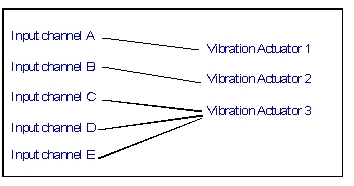
Input channels provide a port into your system so you can plot the frequency response or drive your system with an input force using a vibration actuator. You must create an input function to vibrate your system. A vibration actuator applies an input force to vibrate the system. A vibration actuator can contain expressions that let you use both time and frequency inputs. Each input channel must reference only one vibration actuator. Each vibration actuator, however, can be associated with multiple input channels.
To create an input channel:
1. From the Vibration menu, point to Build, point to Input Channel, and then select New.
2. Follow the instructions in the dialog box help for Create/Modify Vibration Input Channel.
3. Select OK.
To delete an input channel:
1. From the Plugins Tab, select Vibration container. Click and point to Build, point to Input Channel, and then select Delete.
2. From the Database Navigator, select the input channel you want to delete, and then select OK.
3. In the message window that appears, select one of the following:
■Delete All - Deletes the input channel and all of its dependents.
■Remove Parametric Expressions - Deletes the input channel after removing all of its parametric dependencies.
■Cancel - Stops the process without deleting the input channel.
To modify an input channel:
1. From the Plugins Tab, select Vibration container. Click and point to Build, point to Input Channel, and then select Modify.
2. Select the input channel you want to modify.
3. Select OK.
4. Modify the vibration actuator, as needed, by performing the following:
■If you want to associate the input channel with a new actuator, select Actuator Parameters, and enter the appropriate information.
■If you want to create a new vibration actuator, select Existing Actuator, and perform one of the following:
♦Enter the name of the vibration actuator you want to reference.
♦Right-click, select Vibration_Actuator and use the Guesses or Browse to select the vibration actuator.
5. If you want to, modify other parameters as described in Create/Modify Vibration Input Channel.
6. Select OK.
Output Channels
Output channels provide ports in your system at which you examine the frequency response of the system. You can think of output channels as instrumentation ports where you can measure system response and report the results directly in the frequency domain. Output channels can be any valid Adams Solver run-time function, but are typically displacements, velocities, or accelerations.
To create an output channel:
1. From the Plugins Tab, select Vibration container. Click and point to Build, point to Output Channel, and then select New.
2. Follow the instructions in the dialog box help for Create/Modify Vibration Output Channel.
Note: | Measures are not fully supported. To avoid syntactical warnings or errors, be sure to enter the run-time function directly. |
3. Select OK.
To delete an output channel:
1. From the Plugins Tab, select Vibration container. Click and point to Build, point to Output Channel, and then select Delete.
2. From the Database Navigator, select the output channel you want to delete, and then select OK.
3. In the message window that appears, select one of the following:
♦Delete All - Deletes the output channel and all of its dependents.
♦Remove Parametric Expressions - Deletes the output channel after removing all of its parametric dependencies.
♦Cancel - Stops the process without deleting the output channel.
To modify an output channel:
1. From the Plugins Tab, select Vibration container. Click and point to Build, point to Output Channel, and then select Modify.
2. Enter the name of the output channel you want to modify.
3. Modify the output channel, as needed, as described in Create/Modify Vibration Output Channel.
4. Select OK.
Vibration Actuators
Vibration actuators are an Adams Vibration function definition, such as a periodic sine curve, a step, or a spline curve, used to drive an input channel during a forced vibration analysis. The different types are:
Power Spectral Density
The PSD vibration actuator is defined using a spline function. You can specify either a force PSD or a kinematic PSD.
You can specify that different PSD input channels are in cross correlation with each other; the corresponding off-diagonal terms are automatically created for the frequency domain analysis. See the PSD Cross Correlation dialog box.
Learn about computing Power Spectral Density (PSD).
Note: | You cannot combine vibration actuators of the non-PSD-type with PSD-type vibration actuators in the same vibration analysis. |
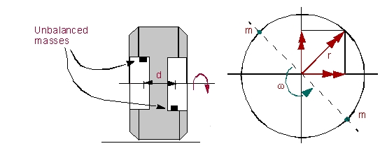
Rotating Mass
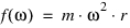
A rotating mass applies a frequency-dependent force. This actuator represents the force due to a rotating mass located at a specified radial offset (distance perpendicular to the axis of rotation). The axis of rotation is defined by the input channel to which this vibrational actuator is applied.
where:
■ is the frequency
is the frequency■ is the unbalanced mass forcing function
is the unbalanced mass forcing function■m is the unbalanced mass
■r is the radial offset of the unbalanced mass from the axis of rotation
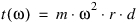
Similarly, a rotating mass placed at a distance offset normal to the plane (distance along the axis of rotation) results in an unbalanced moment.
where:
■ is the moment due to unbalanced mass with offset
is the moment due to unbalanced mass with offset■d is the offset normal to the plane of the unbalanced mass (along the axis of rotation.)
Example
1. Assume one mass (green) in the figure. The leading Force Direction represents the direction of centrifugal force ( ) and points perpendicularly from the axis of rotation to the mass (y-axis in figure). Radial Offset is the perpendicular distance from the axis of rotation to the mass.
) and points perpendicularly from the axis of rotation to the mass (y-axis in figure). Radial Offset is the perpendicular distance from the axis of rotation to the mass. 2. The lagging Force Direction axis points perpendicularly from the axis of rotation to where the mass will be after 90 degrees of rotation (z-axis in figure). Thus it determines the direction of rotation.
3. The leading moment is the moment created by centrifugal force. The Torque Axis is the moment vector created by centrifugal force (z axis in figure). If it is a negative axis, use -d/2 for the "Offset Normal to Plane" or create another marker with an axis pointing in the opposite direction. If a second mass is present as shown (brown), the entered mass value will be the same but the "Offset Normal to Plane" will be twice what you would enter for the single mass case.
The lagging Torque Axis is where the moment vector will point after 90 degrees of rotation (-y axis in the figure). If it is a negative axis, use -d/2 for the "Offset Normal to Plane" or create an-other marker with an axis pointing in the opposite direction. If a second mass is present as shown (brown), the entered mass value will be the same but the "Offset Normal to Plane" will be twice what you would enter for the single mass case.
Swept Sine
Swept sine defines a constant amplitude sine function being applied to the model. The amplitude of the sine function and the starting phase angle are required and must be specified in the Create Vibration Actuator dialog box.

where:
■f is the forcing function
■F is the magnitude of the force
■ is the phase angle
is the phase angle■ is the frequency
is the frequencyUser-Defined Function
You can define any function of the independent variable omega:

where:
■ is the frequency
is the frequency■ is the general function of omega
is the general function of omegaNote: | When the function is evaluated, omega is populated with each frequency from the vibration analysis. |
Macro for Removing Vibration Objects
You can use a utility macro to clean out all vibration entities from a model. This is useful when you want to share your model with other Adams users who will not be using the model for Adams Vibration analysis, allowing them to start with a clean model.
Issue the command associated with the macro from the command line. For example:
mdi vibration model cleanup model=YourModel retain_fd_dampers=no
Note: | ■YourModel is the name of the model from which you want the objects deleted. ■retain_fd_dampers defines whether or not FD damper elements will remain in the model. If set to no, they are deleted. If set to yes, FD damper elements will remain, but all other vibration entities, such as input or output channels, will be removed. |
Limitations
A current limitation in setting up a Forced Vibration Analysis (a.k.a. Frequency Response Analysis) is as follows:
The number of frequency Steps times, the number of Input channels times, and the number of Output channels times must be less than 250000.
Steps * Inputs * Outputs < 250000
The number of frequency steps corresponds to the value for Steps entered in the Perform Vibration Analysis dialog box.