part create flexible_body name_and_position
Allows you to create or modify a flexible body. You specify a modal neutral file (MNF) or a Nastran MD DB file or a Nastran Bulk Data File (BDF), and Adams View creates the necessary Adams View geometry for displaying the flexible body. It also creates a mesh on the flexible body representing the flexible body nodes.
By default, Adams Flex places the flexible body so the flexible body’s local body reference frame (LBRF) is at the origin of the global coordinate system. The LBRF corresponds to the origin of the finite element (FE) environment in which the body was originally modeled. You can also set the location and orientation.
Format:
part create flexible_body name_and_position | |
flexible_body_name = | new flex body |
adams_id = | adams_id |
comments = | string |
view_name = | existing view |
modal_neutral_file_name = | string |
md_db_file_name = | string |
bdf_file_name = | string |
unit_of_length = | string |
unit_of_mass = | string |
unit_of_force = | string |
unit_of_time = | string |
index_in_database = | integer |
matrices = | existing matrix |
damping_ratio = | function |
damping_routine = | string |
generalized_damping = | off/full/internal_only |
dynamic_limit = | real |
location = | location |
orientation = | orientation |
along_axis_orientation = | location |
in_plane_orientation = | location |
relative_to = | existing model part or marker |
exact_coordinates = | exact_coordinates |
invariants = | boolean |
characteristic_length = | real |
representation = | rigid/modal/nforce/none |
stability_factor = | real |
Example:
part create flexible_body name_and_position & | |
|---|---|
flexible_body_name = | flex_body__2 & |
modal_neutral_file_name = | "d:\mscsoftware\adams\con_rod.mnf" & |
comments = | "example of creating a flexible body" |
Description:
Parameter | Value Type | Description |
|---|---|---|
flexible_body_name | New Flex Body | Specifies the name of the flexible body to be created or modified |
adams_id | Integer | Assigns a unique ID number to the part. |
comments | String | Adds comments about the part to help you manage and identify it. |
view_name | Existing View | Specifies the view in which to display the part. You may identify a view by typing its name or by picking it from the screen. In most cases, you can enter the special view name all, which means, all the views currently displayed. You must separate multiple view names by commas. You need not separate multiple view picks by commas. |
modal_neutral_file_name | String | This parameter is mutually exclusive to the MD DB and BDF file arguments. Specifies the name of the MNF. |
md_db_file_name | String | This parameter is mutually exclusive to the MNF and BDF file arguments. Specifies the name of the MD DB file to create one or more flex bodies. |
bdf_file_name | String | This parameter is mutually exclusive to the MNF and MD DB file arguments. Specifies the name of the Nastran BDF. |
unit_of_length | String | Specifies the length unit of data contained in the BDF if not explicitly specified in the BDF. A valid length unit option is km, m, cm, mm, mi, ft, in, um, nm, ang, yd, mil, or uin. |
unit_of_mass | String | Specifies the mass unit of data contained in the BDF if not explicitly specified in the BDF. A valid mass unit option is kg, lbm, slug, gram, ozm, klbm, mgg, sinch, ug, ng, or uston. |
unit_of_force | String | Specifies the force unit of data contained in the BDF if not explicitly specified in the BDF. A valid force unit option is n, lbf, kgf, ozf, dyne, kn, klbf, mn, un, or nn. |
unit_of_time | String | Specifies the time unit of data contained in the BDF if not explicitly specified in the BDF. A valid time unit option is h, min, s, ms, us, nanosec, or d. |
index_in_database | Integer | The parameter applies only, when the user is creating a flexible body out of the MD DB. The parameter specifies the index of the flexible body in the specified MD DB. The parameter is optional. If not specified, it is assumed to have the value 1. |
matrices | Existing Matrix | Specifies the names of seventeen matrices for the modal representation of the flexible body. |
damping_ratio | Function | Specifies the damping ratio to be used. |
damping_routine | String | Specifies the path to user-written subroutine to be used to define modal damping. |
generalized_damping | Off, full, internal_only | Sets generalized damping: ■off - Disables the generalized damping. ■full - Enables the complete generalized damping matrix, including the effects of a resultant damping force. ■internal_only - Only enables the portion of the generalized damping matrix corresponding to the modal coordinates (that is, ignore the resultant damping force). |
dynamic_limit | Real | Specifies the threshold frequency for quasi-static modes. |
location | Location | Specifies x, y, and z coordinates defining the flexible body's location in a given reference frame defined in the parameter relative_to. |
orientation | Orientation | Specifies the orientation method |
along_axis_orientation | Location | Specifies the orientation method. |
in_plane_orientation | Location | Specifies the in_plane orientation method |
relative_to | Existing Model, Part or Marker | Specifies a reference frame relative to which the location and orientation are defined. Leave blank or enter model name to use the global coordinate system. |
exact_coordinates | X, Y, Z, PSI, THETA, PHI, NONE, ALL | Specifies as many as six part coordinates that Adams View is not to change as it solves for the initial conditions. |
invariants | Yes, No | Lists nine on/off values used to control the invariants |
characteristic_length | Real | Specifies the characteristic length of the flexible body for linear limit check. This should be in the model length unit. The linear limit is defined as 10% of this length. |
representation | RIGID, MODAL, NFORCE, NONE | Specifies the representation of the flexible body and if it is eligible for runtime type switching between MODAL (linear) and RIGID representation during a simulation. If MODAL, the flex body will be treated as a linear flex body initially and can be switched to rigid body using the FLEX_BODY Solver command. If RIGID, the flex body will be treated as a rigid body initially and can be switched to linear flexible formulation during the simulation. These two options provide dual representation capability of the flex body during the simulation. If representation is NFORCE, NONE or not specified, the flex body is not eligible for runtime switching. If NFORCE, the flex body's modal representation is Simplified. Its modal representation is converted to a semi-equivalent multi_point_force representation with rigid_body. The stiffness and damping matrix of the multi_point_force is derived from the modal stiffness matrix and modal damping settings. The properties of the rigid_body are derived from the mass invariants of the flexible_body. Note: 1. Setting the representation to RIGID or NFORCE can speed up the simulation without a model change, but may result in loss of fidelity. 2. Dual-representation or NFORCE flexible bodies do not directly support contact with any other bodies. One would have to use dummy part geometry fixed to the flexible body for contact modeling. |
stability_factor | Real | Specifies the amount of damping needed to add to the quasi-static modes to stabilize the simulation. |
Extended Definition:
1. When using the Adams View command language and naming entities, you can use the name later to refer to this entity. Adams View does not allow you to have two entities with the same full name, so you must provide a unique name. Normally, entity names are composed of alphabetic, numeric, or '_' (underscore) characters, and start with an alphabetic or '_' character. For more information, see Using Extended Names. They may be of any length. By enclosing the name in double quotes, you can use other printable characters, or start the name with a numeral. If a name contains characters, or starts with a numeral, you must always quote the name when entering it.
Note that you can specify the parentage of an entity (for example, what part "owns" a marker or a geometry element) when you create it by changing the name. If you enter just the entity name, then Adams View assigns the default parent. If you type in the full name, then you can override the default parent. In most cases, when creating an entity, Adams View provides a default name. The default name that Adams View provides specifies the parentage that it has assumed. You can, of course, delete this name and use your own. The form of a full name is:
"...._NAME.GRAND_PARENT_NAME.PARENT_NAME.ENTITY_NAME"
The number of levels used varies from case to case and the parentage must exist before an entity can be assigned to it.
2. For comments, you can enter any alphanumeric characters. The comments that you create appear in the Information window when you select to display information about the object, in the Adams View log file, and in a command or dataset file when you export your model to these types of files. (Note that design variables are not output to datasets; therefore, neither are their comments.)
3. You can identify an entity, such as a marker or force, by typing its name or by picking it from the screen. If the entity is not visible on the screen, you must type the name. You may also find it convenient to type the name even if the element is displayed.
If an entity is available by default, you can identify it by entering only its name. If it is not, you must enter its full name. To identify a entity under a different part, you may need to enter the model and part names as well. For example, you can specify marker 'pivot' from model 'links', part 'lower_arm' by entering ".links.lower_arm.pivot".
If you type a "?", Adams View lists the entity available by default.
You must separate multiple entity names by commas. If the entity is visible in one of your views, you can identify it by picking it. You need not separate multiple element picks by commas.
Notes: | ■If you created a marker by reading an Adams Solver dataset or graphics file, the marker name is the letters MAR followed by the dataset marker ID number. For example, the name of MARKER/101 is MAR101. If you created the marker during preprocessing, you will have given it a name at that time. ■You may have explicitly named an analysis when you created it by reading one or more Adams output files (graphics (.gra), request (.req), or results (.res)). By default, the name of the analysis is the root name of the Adams output files without the extension. If you created the analysis by reading an Adams graphics file, for example, the analysis name is the name of the graphics file without the .gra extension. ■ The matrices compose the modal integrals used by Adams Solver during simulation. In general, if you enter the MNF, you do not need to specify names for the matrices. ■For the damping_ratio parameter, do one of the following: ■Do not specify to accept the default nonzero damping as follows: ■1% damping for all modes with frequency lower than 100. ■10% damping for modes with frequency in the 100-1000 range. ■100% critical damping for modes with frequency above 1000. ■Enter the scalar damping ratio that you want applied to all modes. ■For example if you would like to apply 1% damping enter 0.01. For more examples you can see FLEX_BODY statement documentation ■Enter Adams run-time function expressions to create complex damping phenomena in your flexible body. In addition, function expressions, such as FXFREQ and FXMODE, allow you to apply different levels of damping to individual modes. Several types of damping are inherently present in mechanical systems. Understanding the source and level of damping are important in the simulation and testing of dynamic systems. For example, a mechanism having low natural frequencies and relatively low damping, could produce damaging motions under resonant conditions. Applying damping judiciously can also improve simulation performance for models containing flexible bodies. For example, consider a flexible body with a 10 kHz mode whose shape is considered essential to allowing the body to assume a particular deformation. Any response in this mode at its resonant frequency dictates integration steps on the order of 1E-5 seconds, which can be unacceptable for long duration simulations. If the damping for this mode is set at 100% of critical damping, however, any resonant response is immediately suppressed. The mode's compliance is retained but its dynamics are eliminated and the simulation performance is improved. |
Damping Dissipation and Damping Matrix
The damping force on a flexible body is proportional to its generalized velocities and is assumed to be derivable from the quadratic form:

where:
■D is a symmetric matrix of damping coefficients
■ is a vector of generalized velocities:
is a vector of generalized velocities: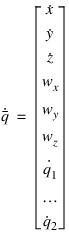
■ are the absolute time derivatives of the position vector coordinates of the local part reference frame with respect to the local part reference frame.
are the absolute time derivatives of the position vector coordinates of the local part reference frame with respect to the local part reference frame.■ are the angular velocity vector coordinates with respect to the local part reference frame.
are the angular velocity vector coordinates with respect to the local part reference frame. ■ are the time derivatives of the modal coordinates.
are the time derivatives of the modal coordinates.The matrix D is composed of two parts, Dm and Dg:

Dm represents the contribution of proportional modal damping, and Dg represents the contribution of a generalized damping matrix. Both are explained in the next section.
Specifying Modal Damping
The modal damping matrix Dm is diagonal and defined using critical damping ratios for each mode i= 1,n.
for each mode i= 1,n.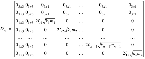
where  and
and  are the generalized stiffness and mass for mode i.
and are the generalized stiffness and mass for mode i.Note: | The damping ratio  does not need to be constant. It can be a function of time or system state. does not need to be constant. It can be a function of time or system state. |
If you do not specify modal damping when you create the flexible body, Adams Flex applies a default, non-zero critical damping ratio as follows:
■1% damping for all modes with frequency lower than 100.
■10% damping for modes with frequency in the 100 to 1000 range.
■100% critical damping for modes with frequency above 1000.
You can change the default modal damping in three ways:
■Assign a single scalar critical damping ratio that Adams Flex applies uniformly to all modes.
■Enter Adams run-time function expressions to create complex damping phenomena in your flexible body. In addition, function expressions, such as FXFREQ and FXMODE, allow you to apply different levels of damping to individual modes.
■Control the damping using the DMPSUB user-written subroutine. DMPSUB lets you set different levels of damping for different modes and the damping can vary over time. For more on writing subroutines, see the Subroutines section of the Adams Solver online help.
To assign modal damping when creating or modifying a flexible body:
1. In either the Create a Flexible Body dialog box or Flexible Body Modify dialog box, clear the selection of default (use default in the Create a Flexible Body dialog box).
2. In the Damping Ratio text box, either:
■ Enter the critical damping ratio.
■Enter a function. To get help building the function, next to the Damping Ratio text box, select the More button  . The Adams View Function Builder appears. For information on using the Function Builder, see the Adams View Function Builder online help.
. The Adams View Function Builder appears. For information on using the Function Builder, see the Adams View Function Builder online help. 3. Continue creating or modifying the body, and then select OK.
Specifying Generalized Damping
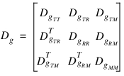
The generalized damping matrix Dg is a constant symmetric matrix of the form:
To better understand how the generalized damping matrix is handled in Adams Flex, it is helpful to start with the discrete finite element equations of motion
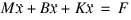
where:
■M, B, and K are the finite element mass, stiffness, and damping matrices, respectively.
■ is the nodal coordinate vector.
is the nodal coordinate vector.■is the applied force vector.
The damping matrix B is derived from damping elements and parameters defined in the finite element model. The previous equation can be transformed into modal coordinates:
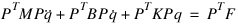
where P is the matrix of mode shapes stored column-wise and q is the vector of modal coordinates PTBP represents the generalized damping matrix. However, before Adams Flex can use the generalized damping matrix, the portion PTBP of that projects onto the rigid body modes must be transformed to the nonlinear, large motion, generalized coordinates: X, Y, Z,  ,
,  , and
, and used to represent the flexible bodys large overall motion in Adams Solver (C++). To this end, a m x 6 transformation matrix, A, is constructed and transforms m rigid body modes to the six coordinates X ,Y, Z,
  ,
,  , and
, and  , and the final generalized matrix Dg is computed:
, , and used to represent the flexible bodys large overall motion in Adams Solver (C++). To this end, a m x 6 transformation matrix, A, is constructed and transforms m rigid body modes to the six coordinates X ,Y, Z, , , and , and the final generalized matrix Dg is computed: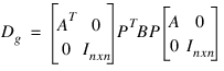
If the damping description in the finite element model results in a resultant damping force, there will be nonzero entries in the sub-matrices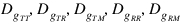 . Because the resultant damping force was derived from a linear finite element model governed by small strain approximations and infinitesimal rotations, a resultant damping force may yield unexpected results in the context of large overall motion supported in Adams. Therefore, Adams Flex provides the option to ignore the resultant damping force. Ignoring a resultant damping force is referred to as internal-only generalized damping.
. Because the resultant damping force was derived from a linear finite element model governed by small strain approximations and infinitesimal rotations, a resultant damping force may yield unexpected results in the context of large overall motion supported in Adams. Therefore, Adams Flex provides the option to ignore the resultant damping force. Ignoring a resultant damping force is referred to as internal-only generalized damping.Because the generalized matrix Dg is derived from the component finite element model, you can leverage the damping elements and features in the finite element program. This is particularly useful for defining non-proportional and spatially-dependent damping. Furthermore, the generalized damping matrix is stored in the MNF to be optionally applied to the flexible body. That is, because you defined damping in the finite element model, it is not necessary to employ it in Adams. To enable generalized damping, however, you must have a generalized damping matrix stored in your MNF.
To specify generalized damping when creating or modifying a flexible body:
1. In either the Create a Flexible Body dialog box or Flexible Body Modify dialog box, set Generalized Damping to:
■Off - Disables the generalized damping.
■Full - Enables the complete generalized damping matrix, including the effects of a resultant damping force.
■Internal Only - Only enables the portion of the generalized damping matrix corresponding to the modal coordinates (that is, ignore the resultant damping force).
2. Continue creating or modifying the body, and then select OK.
3. Orientation of rigid or flexible body using three rotation angles. Adams View orients the body starting from the initial coordinate system and applying three successive rotations. Depending on the convention you select, the rotations occur about space-fixed or body-fixed axes in any combination of the x, y, and z axes. By default, you supply body 313 (body-fixed z, x, z) angles.
Adams View applies your orientation angles with respect to the coordinate system in the Orientation Relative To or Relative To text box.
Adams View applies your orientation angles with respect to the coordinate system in the Orientation Relative To or Relative To text box.
Along Axis Orientation
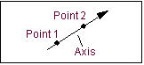
Orientation of a rigid or flexible body by directing one of its axes. Adams View assigns an arbitrary rotation about the axis. Two points are needed to define an axis but you can enter either one or two points to direct the axis. If you enter two points, the axis points from the first location to the second. If you enter one point, Adams View uses the location you specified in the Location text box as the first point and the new location as the second point.
Along Axis Orientation
Adams View applies the location coordinates in the coordinate system you identify in the Location Relative To or Relative To text box.
Note that this does not completely dictate the orientation of the coordinate system. Adams View positions the coordinate system with an arbitrary rotation about the axis. If you must completely control the coordinate system orientation, select Orientation or In Plane Orientation.
By default, you direct the z-axis of the coordinate system. You can use the DEFAULTS ORIENT_AXIS_AND_PLANE AXIS_AND_PLANE_SETTING command to change this convention. For example, selecting either X_AXIS_XY_PLANE or X_AXIS_XZ_PLANE directs the x-axis. The plane-convention setting does not affect this parameter.
You can also direct the axis graphically using the marker’s position handle. Simply point the appropriate axis on the marker in the desired direction.
In Plane Orientation
Orientation of the rigid or flexible body by directing one of the axes and locating one of the coordinate planes.
In Plane Orientation
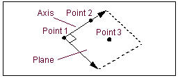
To define an axis and a plane, you need three points. You can enter either two or three locations, however. If you enter three locations, the axis points from the first location to the second and the plane is parallel to the plane defined by the three locations. If you enter only two locations, Adams View uses the location you specified in the Location text box as the first point and the other two locations as the second and third points.
Adams View applies the location coordinates in the coordinate system in the Relative To text box.
By default, you direct the z-axis of the coordinate system marker and locate the zx plane. You can use the DEFAULTS ORIENT_AXIS_AND_PLANE AXIS_AND_PLANE_SETTING command to change this convention. For example, selecting X_AXIS_XY_PLANE directs the x-axis and orients the xy plane.
4. The six coordinates for the exact_coordinates parameter are:
■X - X coordinate
■Y - Y coordinate
■Z - Z coordinate
■PSI - Psi angle
■THETA - Theta angle
■PHI - Phi angle
You can enter these coordinates in any order. If Adams View has to alter the part position to obtain consistent initial conditions, it does not vary the coordinates you specify with this parameter unless Adams View must vary them to satisfy the initial conditions you specify for a joint or for a motion.
5. Adams Flex computes the time varying mass matrix of the flexible body using nine inertia invariants. (For details, see Theory of Flexible Bodies.) Four combinations of invariants have special significance and they are provided with Adams Flex. In most cases, the modal basis in the MNF is an orthogonal set including six rigid body modes. Theoretically, invariant 3 and 4 are zero in this situation even though you may see some small non-zero entries due to numerical errors. So, invariants 3 and 4 are disabled in all the four combinations by default. If you want to enable them, you can choose to customize the invariant formulation. The standard formulations are:
■Rigid body - In this formulation, Adams Flex disables invariant 6, the modal mass, and the flexible body is considered rigid. Adams View ignores all modes, even those you enable, during the simulation. The results of the flexible body simulation closely resemble those for an Adams rigid part although formulation differences can cause subtle result variations.
■Constant - In this formulation, Adams Flex disables invariants 3, 4, 5, 8 and 9. The flexible body's inertial properties are unaffected by deformation (that is, deformation and rigid body motion are uncoupled).
The Constant option may only have academic value because computational savings will be modest while potentially having a dramatic effect on results. When you select Constant, Adams View does not account for changes in the moment of inertia due to deformation.
■Partial coupling - In this formulation, which is the default, Adams Flex disables invariants 3, 4, 5 and 9. Invariants 5 and 9 provide a second-order correction to the flexible body inertia tensor. These invariants impose the greatest computational overhead on the evaluation of the flexible body equations of motion. Disabling these invariants can reduce CPU time significantly while having minor impact on results in most cases.
■Full coupling - In this formulation, Adams Flex enables all of the invariants except for invariants 3 and 4. Use this method to achieve full accuracy.
When Adams Flex creates a flexible body, it uses the Partial Coupling formulation by default because Partial Coupling has significant computational efficiency over the more accurate Full Coupling formulation. You should verify, however, that your model does not require Full Coupling.
You should always be careful when using the Constant formulation even when you expect deformations to be small. Use it only after careful experimentation.
The Rigid Body formulation removes all flexibility effects, and you should only use it as a debugging tool.
To set a modal formulation:
1. In the Inertia modeling area of the Flexible Body Modify dialog box, select a formulation option or select Custom.
When you select Custom, Adams Adams Flex displays a Custom Inertial Modeling dialog box that lets you set up the invariants that you want selected.
2. Use the dialog box to select the inertia invariants, and then select OK.
You can also use this dialog box to view the effects of the different options. For example, select Partial Coupling to view the invariants that option disables and enables.