FLEX_BODY
The FLEX_BODY statement defines a linear or nonlinear elastic body. The FLEX_BODY is capable of undergoing large motion. For a linear FLEX_BODY this motion is, characterized by six nonlinear generalized coordinates for a body coordinate system (BCS). The small, linear elastic deformations of the FLEX_BODY relative to this BCS are described by a linear combination of mode shapes. These modal amplitudes are additional generalized coordinates for the FLEX_BODY. The body can be connected to the rest of the mechanical system through applied forces and kinematic constraints.
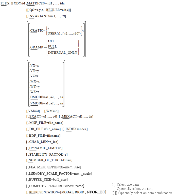
Format
Arguments
BDF_FILE = filename | Specifies the path to the Nastran Bulk Data File (BDF) which will be read in to create a non-linear flexible body in Adams. This BDF file will be a complete run-ready Nastran deck that will include the executive and case controls as well as the bulk data. This is one of the three ways to specify the detailed properties of a flexible body (See MNF_FILE and DB_FILE for the alternative). Note that this argument is required by Adams Solver (C++) to define a nonlinear flexible body. |
CHAR_LEN = c_len | Specifies the characteristic length of this flexible body for linear limit check. This should be in the model length unit. The linear limit is defined as 10% of this length. If user enables linear limit check (See PREFERENCES/FLEX_LIMIT_CHECK) and does not specify this length, Adams Solver (C++) will try to calculate it directly from the MNF or MD DB file specified in MNF_FILE or DB_FILE. If it fails to do so, a warning will be issued and the linear limit check on this flexible body will be disabled. |
 | Specifies modal damping as a fraction of critical damping. You can specify modal damping using a function expression or a user-written subroutine. To define the modal damping with an expression, follow CRATIO with an equal sign and the expression. The FXFREQ and FXMODE function expression may be useful here. To define modal damping with a user-written subroutine, follow CRATIO with an equal sign, the character string USER, and the values (r1[,...,r30] that the Adams Solver (C++) is to pass to the DMPSUB user-written subroutine. If the CRATIO argument is used, it must either be the last argument in the FLEX_BODY statement, or be followed by a backslash (\). If you omit CRATIO, Adams Solver (C++) applies default damping as follows: ■1% to modes under 100 Hz ■10% to modes under 1 kHz ■Full critical damping to modes over 1 kHz You can disable the default damping by specifying CRATIO=0. |
DB_FILE=file_name | Specifies the path to the MD DB file that defines the detailed properties of the flexible body. If there are more than one flexible bodies stored in the database, an INDEX argument should be specified to identify the body. This is one of the three ways to specify the detailed properties of a flexible body (See MNF_FILE and BDF_FILE for the alternatives). Note that this argument (or MNF_FILE or BDF_FILE) is not required by Adams Solver (C++) unless flexible body contact is defined, but is required by Adams View. |
DMODE=a1,a2,...,an | Specifies the initial values of the modal generalized coordinates. Default: 0 Range: Real values |
DYNAMIC_LIMIT=d | Specifies the dynamic limit frequency of this flexible body in Hertz. Modes whose frequencies are higher than d will be treated as quasi-static modes, that is, the dynamic effects (  and and  terms) are ignored in dynamic simulation. So for quasi-static mode, the equation of motion is just terms) are ignored in dynamic simulation. So for quasi-static mode, the equation of motion is just  , where K is the generalized stiffness, q is the modal coordinate and F is the modal force acting on this mode, which may include the coupling effects with other DOFs of flexible body. When only static deformations are of interest for a particular simulation, using the dynamic limit may improve the simulation performance for models that have a lot of high-frequency modes. , where K is the generalized stiffness, q is the modal coordinate and F is the modal force acting on this mode, which may include the coupling effects with other DOFs of flexible body. When only static deformations are of interest for a particular simulation, using the dynamic limit may improve the simulation performance for models that have a lot of high-frequency modes.The damping specified by CRATIO or GDAMP will be ignored for quasi-static modes. Please refer to STABILITY_FACTOR on how to specify damping on quasi-static modes. Default: +  |
EXACT=c1:...:c6 | Specifies as many as six rigid body coordinates of the BCS that Adams Solver (C++) should not change as it iteratively solves for initial conditions which satisfy all constraints. The six coordinates are: X - x coordinate Y - y coordinate Z - z coordinate PSI - Psi angle THETA - Theta angle PHI - Phi angle These coordinates can be entered in any order following EXACT. Adams Solver (C++) does not change coordinates unless the values specified are inconsistent with initial conditions for a joint or defined motion. Default: None Range: X, Y, Z, Psi, Theta, or Phi |
 | Specifies how the generalized damping matrix referenced in the MATRICES argument should be applied to the FLEX_BODY. If GDAMP is OFF, the generalized damping matrix is ignored. If FULL is specified, the generalized damping matrix is applied to both the rigid and modal coordinates of the FLEX_BODY. If you specify INTERNAL_ONLY, only the portion of the generalized damping matrix corresponding to the modal coordinates is applied. Default: OFF Note: You can only specify the GDAMP argument if you have defined a GENDAMP matrix for the associated FLEX_BODY. |
INDEX=index | Specify the index of the flexible body in DB_FILE. MD DB is capable of storing more than one flexible body. Default: 1 |
INVARIANTS=c1:...:c9 | Specifies a true and false pattern indicating which of the nine inertia invariants Adams Solver (C++) should use to model inertia coupling of the flexible and rigid body motion. The order of the patterns corresponds to the nine successive inertia invariants. For more details on the inertia invariants, see the Theory of Flexible Bodies in Adams Flex. The following combinations have special significance: T:T:F:F:T:T:T:T:T - Full inertia coupling of deformation and rigid body motion. T:T:F:F:F:T:T:T:F - Ignore second-order deformation corrections to the inertia tensor, and the first-order corrections to the rotational and flexible inertia coupling. This is also called partial coupling. T:T:F:F:F:T:T:F:F - Neglect all deformation corrections to the mass matrix. *:*:*:*:*:F:*:*:* - Disable all deformations. The pattern T:T:F:F:F:T:T:T:F is the default, because although it potentially sacrifices small levels of accuracy compared to the first pattern of full inertia coupling, it does so with significant computational savings. If an MNF has six rigidbody modes in it, theoretically, invariants 3 and 4 should be zero even though there may be some non-zero entries in the MNF file due to numerical errors. This is the reason that they are disabled by default. The pattern T:T:F:F:F:T:T:F:F should be used with great care, because it only returns an accurate answer when the flexible component is quite rigid. The pattern *:*:*:*:*:F:*:*:*, where the * can be either T or F, offers a way to turn off all flexibility in the structure, usually for debugging purposes. Note that even with this last pattern, the FLEX_BODY statement does not function like a PART statement, due to formulation differences. It is hard to envision circumstances where it is appropriate to disable invariants 1 (the total mass), 2 (the undeformed CM location), and 7 (the undeformed inertia tensor). Disabling these normally causes a numerical singularity. Default: T:T:F:F:F:T:T:T:F |
MATRICES=id1,...,idn | Specifies identifiers of matrices that contain the properties of the FLEX_BODY, such as inertia, node locations, mode shape information, applied modal loads, and preloads. Each matrix is defined via a MATRIX statement. Normally, these matrices are generated by a modal flexibility preprocessor (MNF2MTX), which writes these matrices to a file. The MATRIX statement then references this file, along with the appropriate name from the list below. To learn more about this process, see Creating Matrix Files. The FLEX_BODY recognizes the following matrix names. Their identifiers can be specified in any order. SELMOD: A list of selected modes and their natural frequency. SELNOD: A list of selected nodes and their location and flag of interface node. GENSTIFF: The generalized stiffness matrix. INVAR1: Invariant 1 - the total mass of the flexible body. INVAR2: Invariant 2 - the mass scaled, undeformed center of mass location. INVAR3: Invariant 3 - First order modal deformation correction to center of mass. INVAR4: Invariant 4 - Inertial coupling matrix of deformations and rotations. INVAR5: Invariant 5 - First order correction to the flexible inertia coupling. INVAR6: Invariant 6 - the generalized modal mass. INVAR7: Invariant 7 - the moment of inertia. INVAR8: Invariant 8 - First order modal deformation correction to the moment of inertia (INVAR7) INVAR9: Invariant 9 - Second order modal deformation correction to the moment of inertia (INVAR7) T_MODE: Translational mode shape of selected modes at selected nodes. R_MODE: Rotational mode shape of selected modes at selected nodes. PRELOAD: The preload on the selected modes. MODLOAD: The modal loadcases on the selected modes. GENDAMP The generalized damping matrix. EDGE_xx: A list of selected nodes which define an edge of the flexible body (xx denotes an arbitrary edge id). Default: None Range: Adams identifiers |
MEXACT=d1, d2, ..., dn | Specifies as many as n modal body coordinates that Adams Solver (C++) should not change as it iteratively solves for initial conditions that satisfy all constraints. The variable n is the number of modal coordinates. These coordinates can be entered in any order following MEXACT. They are not changed by Adams Solver (C++) unless the values specified are inconsistent with initial conditions for a joint or defined motion. Default: None Range: Active mode numbers |
MNF_FILE=file_name | Specifies the path to the modal neutral file that defines the detailed properties of the flexible body. This is one of the three ways to specify the detailed properties of a flexible body (See DB_FILE and BDF_FILE for the alternatives). Note that this argument( or DB_FILE or BDF_FILE) is not required by Adams Solver (C++) unless flexible body contact is defined, but is required by Adams View. |
STABILITY_FACTOR=s | Specifies the stability factor for quasi-static modes when the dynamic limit feature is enabled on this flexible body. If the modal force acting on quasi-static mode has high frequency component, it may affect the convergence of dynamic simulation. In this case, user can specify artificial damping to stabilize the solution using this argument. The damping added to the mode will be s times of critical damping. So the equation of motion of quasi-static mode will be  , where , where  is the frequency of the mode. is the frequency of the mode. Default: 10.0 |
NUMBER_OF_THREADS=n | Specifies the number of threads to be used on each nonlinear flexible body. A separate process is used to solve a nonlinear flexible body. To specify more than one thread in solving a flexible body on this process, set Number of threads > 1. The number of threads, n, must be an integer in the range of 1 to 8. The default is 1. |
QG=x,y,z | Defines the Cartesian initial coordinates of the BCS with respect to the ground coordinate system. Default: 0.0, 0.0, 0.0 Range: Real values |
FEA_MEM_SETTINGS=mem_size | Specifies the size of memory to be used on each nonlinear flexible body. The mem_size can be specified as a positive real number in megabytes. This argument has priority over MEMORY_SCALE_FACTOR if it's also specified. Default: Use half of the amount of physical memory |
MEMORY_SCALE_FACTOR=mem_scale | Specifies the scale factor of the amount of physical memory to be used on each nonlinear flexible body. The mem_scale can be specified as a positive real number less than or equal to 0.8. If zero is specified, 0.5 is used as the default. If the model has more than one nonlinear flexible body, mem_scale will be automatically divided by the number of nonlinear flex bodies in the model. This argument will be ignored if FEA_MEM_SETTINGS is specified. Default: 0.5 divided by the number of nonlinear flex bodies |
BUFFER_SIZE=buff_size | Specifies the number of words per I/O record to be used for the nonlinear flexible body. buff_size can be specified as a positive integer number less than or equal to 65537. Recommended buff_size settings based on FE model size (DOF ranges) are: 8193 (DOF <= 100,000) 16385 (100,000 < DOF <= 400,000) 32769 (400,000 < DOF <= 1,000,000) 65537 (DOF > 1,000,000). Default: Estimated based on the FE model size |
COMPUTE_RESOURCE=host_name[:port_number] | Specifies the name of a remote host machine and optionally port number to be used to solve each nonlinear flexible body. If host_name is specified, the NLFE name server has to be started on the remote host machine, and then the remote kernel has to be started on the machine where Adams is running using the Adams-NLFE Client Manager, before a simulation can be launched. The default of port_number is 45000 and specify to change if it's busy. For more information on the Adams-NLFE Client Manager see "Using Distributed Computing for Nonlinear Adams Flex Bodies" in Chapter 7 of the Installation and Operations Guide. Default: None |
REPRESENTATION= {MODAL, RIGID, NFORCE} | Specifies that the flexible body is eligible for runtime type switching between MODAL and RIGID representations during a simulation, or if the simple flex method (NFORCE) is employed. If MODAL, the flexible body will be treated as a flexible body initially and can be switched to RIGID with the FLEX_BODY command. If RIGID, the flexible body will be treated as a rigid body initially and can be switched to MODAL with the FLEX_BODY command during the simulation. If NFORCE, an equivalent formulation of NFORCE statement is applied and stiffness and/or damping property is only considered based on a MNF and cannot be switched during the simulation. If REPRESENTATION is not specified, the flexible body is not eligible for runtime type switching and original MODAL formulation is applied. Note: 1. Setting the REPRESENTATION of the flexible body to RIGID can speed up the simulation with no model change, but can result in a loss in fidelity. 2. Dual-representation or flexible bodies using the simple flex method (NFORCE) do not directly support contact with any other bodies nor modal force. One would have to use dummy part geometry fixed to the flexible body for contact modeling. 3. The simple flex method (NFORCE) can speed up the simulation with stiffness and/or damping property but dynamic property will be ignored. CRATIO can be specified as proportional damping ratio as same as NFORCE. Function expression and GDAMP are not allowed. 4. In flexible bodies using the simple flex method, NFORCE formulation is applied on interface nodes and other nodes are attached to a rigid body and the 5th column of SELNOD in MTX file is the flag of interface node. If old MTX file (4 columns SELNOD) is used, all attachment nodes are recognized as interface node and it may cause singularity. In addition, all interface nodes needs to have accurate stiffness of 6 degrees of freedom, for example in Nastran, 123456 have to be defined as ASET. If not, it also may cause singularity. 5. The representation argument is ignored by the FLEX_BODY statement when it is a MaxFlex flexible body. |
REULER=a,b,c | Defines the 3-1-3 Euler angles that Adams Solver (C++) uses to establish the initial orientation of the BCS with respect to the ground coordinate system. The a, b, and c rotations are in radians and are, respectively, about the z-axis of ground, new x-axis, and new z-axis of the BCS. To input Euler angles in degrees, you should add a D after each value. Default: 0.0, 0.0, 0.0 Range: Real values |
VM=id | Specifies the identifier of the marker that specifies the direction of translational velocity initial conditions (VX, VY, and VZ). VM defaults to global orientation. |
VMODE=b1,b2,...,bn | Specifies the initial values of the time rate of change of the modal generalized coordinates. Default: 0 Range: Real Values |
VX=x,VY=y,VZ=z | Specifies the initial translational velocities of the Body Coordinate System (BCS) along the x-axis (VX), y-axis (VY), and z-axis (VZ) of the VM coordinate system. Default: 0 Range: Real values |
WM=id | Specifies the identifier of the marker that specifies the axes about which angular velocity initial conditions (WX, WY, and WZ) are defined. WM defaults to the BCS location and orientation. The origin of the WM marker lies on the axis of rotation. This is most useful for rotating systems. |
WX=a,WY=b,WZ=c | Specifies the initial rotational velocities of the BCS along the x-axis (WX), y-axis (WY), and z-axis (WZ) of the WM coordinate system. Default: 0 Range: Real values |
Tip: | ■The Adams Flex Toolkit is used to generate the input matrices in the Adams Solver matrix format. For more information on generating matrix files for the FLEX_BODY statement, see Translating an MNF or an MD DB into a Matrix File. ■The intrinsic variables FXMODE and FXFREQ are available so you can write function expressions that define CRATIO as a function of mode number and/or modal frequency (see FXMODE and FXFREQ functions). ■You can query the location, orientation, translational velocity and angular velocity of a FLEX_BODY using the SYSARY utility subroutine with the FXDISP, FXDC, FXTVEL and FXRVEL options. See the SYSARY documentation for details. ■If your FLEX_BODY undergoes high-speed, rigid body rotations about a stationary axis, significant solver performance can be realized by aligning the z-axis of the body coordinate system (BCS) with the spin axis. Because the BCS of the FLEX_BODY is defined by the basic coordinate system in the finite element model, re-orientating the BCS with respect to the body requires you to re-orient the finite element model with respect to its basic coordinate system. In MSC.Nastran, this can be done easily with CORDxx Bulk Data entries. |
Caution: | ■All nodes to which markers are attached must be present in the SELNOD matrix. ■Function expressions defining CRATIO should be functions of TIME, MODE, FXMODE, and/or FXFREQ only. ■Flexible body CONTACT is only supported when using Adams Solver (C++). ■Only use modes with nonzero eigenvalues. A mode with a zero eigenvalue (or frequency) represents a rigid body degree of freedom that is already introduced by the BCS. ■Due to the numeric methods involved, rigid body modes may have nonzero eigenvalues/frequencies. Typically, these eigenvalues are numerically small. Using these modes will cause simulation problems. ■If there are less than six rigid body modes in the MNF it is strongly recommended to enable INVAR3 and INVAR4 using INVARIANTS argument. ■None zero modal generalized velocities may be observed when switching from RIGID to MODAL because reconciliation is done by solver to satisfy the constraints. |
Examples
FLEX_BODY/1
, MATRICES=1,2,3,4,5,6,7,8,9,10,11,12,13,14
, CRATIO=0.0\
, DMODE=.0,.0,.0,.0
, VMODE=.0,.1,.0,.0
This statement defines a flexible body with a damping ratio of 0.0 on all modes. Zero initial modal displacements are specified by the DMODE argument. The VMODE argument specifies an initial modal velocity for mode 2 of 0.1.
FLEX_BODY/1
, CRATIO = STEP(TIME, 0.1, 1.0, 1.2, STEP(FXFREQ, 3000, 0.02, 10000, 0.2))\
,MATRICES = 1, 2, 3, 4, 5, 6, 7, 8, 9, 10, 11, 12, 13, 14
, CRATIO = STEP(TIME, 0.1, 1.0, 1.2, STEP(FXFREQ, 3000, 0.02, 10000, 0.2))\
,MATRICES = 1, 2, 3, 4, 5, 6, 7, 8, 9, 10, 11, 12, 13, 14
This example specifies modal damping that varies both with time and modal frequency, such that all modes have 100% critical damping until t=0.1, after which:
■Modal damping decreases smoothly to between 2% and 20% of modal damping at time=1.2.
■Modes with modal frequencies less than 3,000 reach 2% modal damping.
■Modes with modal frequencies above 10,000 reach 20% modal damping.
■Modes with modal frequencies between 3,000 and 10,000 reach modal damping values smoothly distributed between 2% and 20%.
FLEX_BODY/1,
, CRATIO = IF(FXFREQ-100:0.01,0.1,if(FXFREQ-1000:0.1,1.0,1.0)\
,MATRICES = 1, 2, 3, 4, 5, 6, 7, 8, 9, 10, 11, 12, 13, 14
, CRATIO = IF(FXFREQ-100:0.01,0.1,if(FXFREQ-1000:0.1,1.0,1.0)\
,MATRICES = 1, 2, 3, 4, 5, 6, 7, 8, 9, 10, 11, 12, 13, 14
This example recreates the default modal damping scheme using nested IF function expressions.
FLEX_BODY/1,
, MATRICES = 1, 2, 3, 4, 5, 6, 7, 8, 9, 10, 11, 12, 13, 14
, MNF_FILE=C:/models/link.mnf
This example specifies the detailed properties of this flexible body are in a MNF file, C:/models/link.mnf.
FLEX_BODY/1,
, MATRICES = 1, 2, 3, 4, 5, 6, 7, 8, 9, 10, 11, 12, 13, 14
, DB_FILE=C:/models/demo.MASTER, INDEX=3
This example specifies the detailed properties of this flexible body are stored as the third body in an MD DB file, C:/models/demo.MASTER.
FLEX_BODY/1
,MATRICES = 1, 2, 3, 4
, BDF_FILE = DEMO_FLEX_BODY_1.dat
,NUMBER_OF_THREADS=4
This statement defines a non-linear flexible body which will have 4 threads allocated on the compute machine. This non-linear flexible body has the Nastran Input file DEMO_FLEX_BODY_1.dat which will contain all the information needed for the nonlinear finite element solution such as Solution Type, Model Definition, Loading, Boundary Conditions and so on.
FLEX_BODY/1,
, MATRICES = 1, 2, 3, 4, 5, 6, 7, 8, 9, 10, 11, 12, 13, 14
, DYNAMIC_LIMIT=500.0
This statement defines a flexible body with a dynamic limit of 500.0 Hz. Any mode that is higher than 500.0 Hz will be treated as quasi-static mode. A damping of 10 times the critical damping will be applied to these modes.
FLEX_BODY/1,
, MATRICES = 1, 2, 3, 4, 5, 6, 7, 8, 9, 10, 11, 12, 13, 14
, DYNAMIC_LIMIT=1.0e3
, STABILITY_FACTOR=0.0
This statement defines a flexible body with a dynamic limit of 1000.0 Hz. Any mode that is higher than 1000.0 Hz will be treated as quasi-static mode. No damping is applied to the quasi-static modes (Note that solution may become unstable if there is high frequency excitation).
See other Inertia and material data statement available.