Building FE Parts
The FE_Part is composed of small pieces, known as finite elements. The behavior of each element is well known under all possible support and load scenarios. The elements share common points called nodes, section properties are assigned on each node. The basic building blocks to create FE_Part are described below:
■Material - Defines a collection of constants needed to define the stress-strain relationship for a given physical material. Currently, only elastic behavior is supported. The number of constants varies depending on whether the material is isotropic, orthotropic, or anisotropic.
■Nodes - Define the neutral axis of the beam, whose axis passes through the origin of each node. All nodes must be oriented such that the positive x-axis is tangent to the neutral axis of the beam centroid. To this end, we need to specify the location and orientation of the node with respect to the BCS of the element. Also, the number of nodes used, n, determines the number of degrees of freedom (DOF) of the FE Part as such:
DOF for 3DBeam : = 3*((4*number_of_nodes)-1),
DOF of 2DBeams : = 4*(number_of_nodes).
Within Adams View these nodes are objects with names (typical of other Adams View objects) and labels which are single positive integer identifiers passed to Adams Solver. The modeling automation provided by the FE Part create and modify wizard in Adams View will name and label nodes in a consistent fashion, but users may rename FE Nodes.
■Section Properties - Define the cross-sectional property values for each node specifying area and area moments of inertia (Iyy, Izz and Iyz) of the beam.
Interacting with Adams Modeling Elements
The FE Part interacts with the rest of the Adams model similar to other body types in Adams.
■Markers - Markers on FE Parts must be associated with a single node. The marker need not necessarily be coincident with a node. Adams Solver will compute the initial offset to the node and it will keep the offset in subsequent computations. The marker will move as if it is rigidly attached to its node. Within Adams View an FE Part marker can be defined as either location-based or node-based. During pre-processing, the location based marker will always remain at the specified location and automatically associate itself with the nearest node even after "re-meshing" the FE Part.
■The node-based marker will always remain associated with the specified node even if it is not the nearest node. Markers automatically generated on FE Parts by Adams View, for example when interactively creating a constraint or force, will be location-based.
■The FE Part does not support a floating markers. So, an FE Part cannot be the reaction body for a torque vector (VTORQUE), force vector (VFORCE), general force (GFORCE), curve-curve constraint (CVCV) or point-curve constraint (PTCV).
■Constraints - Through markers, the full suite of Adams constraints (for example, joints, joint primitives, and motions) can be applied to an FE Part.
■Applied Forces - Through markers, the full suite of Adams point forces (for example, single component and multi-component forces and torques) can be applied to an FE Part.
■Contact - Geometry belonging to an FE Part can be used for FE Part-Solid or FE Part-FE Part contact force definitions. FE Part-Flexible Body contact force definitions are not supported currently. To learn more about modeling contact between FE Part and other bodies in Adams see Contacts section.
■FE Load - A distributed applied load (force and moment) per unit length on a beam using function expressions can be defined and is known as the FE Load. The function expressions can depend on, among other things, runtime functions which define quantities along the length of the FE Part centerline (S, SD, SV and SA). Function S defines the position along the length of the centerline as a value between 0 and 1. The other measures provide the values of the global position, velocity and acceleration at the position defined by S.
Building within Adams View: the FE Part Wizard
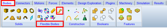
FE Part creation and modification is supported within Adams View primarily through the FE Part wizard. This wizard is launched either via a modification action on FE Part or, for creation purposes, via the FE Part icon within the "Flexible Bodies" container on the "Bodies" tab:
The wizard is divided into three pages. The specific details regarding each input item are provided in the FE Part Wizard dialog box help. A summary of the modeling capabilities enabled by each page of the FE Part wizard are summarized below.
Formulation Page
On the Formulation page the formulation option (described in the Introduction) is selected and the material properties are specified. Aside from damping ratios, the material property definition for the FE Part references a standard Adams material object. This material definition was expanded for the FE Part. In addition to the isotropic definition option, it also supports an orthotropic beam and anisotropic beam both of which can be applied to, and utilized by, the FE Part.
Centerline Page
On the Centerline page one defines a guide to be used for the definition of the FE Part beam centerline. This can be specified as a straight line between two markers or a graphical curve (B-spline) or coordinate (x, y, z points). This guide is then used, on the subsequent page, to specify the start and end of the FE Part centerline and is used to pick locations for any intermediate nodes. It should be noted that this guide does not belong to the FE Part (it is not referenced by the eventual Adams Solver dataset content relevant to the FE Part) and that the actual FE Part centerline can differ from this guide depending on the shape of the guide and the number of nodes used in the FE Part. The actual centerline of the FE Part will be determined by an interpolation through the nodes defined on the Nodes page of the wizard. The selected reference curve is hidden automatically after FE part's creation so as to make the FE Part's centerline more easily seen.
Nodes Page
On the Nodes page, the FE Part's nodes are defined. All FE Parts must have at least two nodes - which define the start and end of the beam. The table on this page allows one to add more nodes at locations defined by their distance along the length of the centerline (S) or x, y, z coordinates.
At each node it is required to define the cross-sectional properties of the beam. This is done with Adams View by creating and referencing a section object. Each section must have area and area inertia values specified since this is what Adams Solver uses to calculate the behavior of the FE Part. The FE Part can have different cross-sectional properties at each node.
Nodes Parameterization
The "Parameterize" option on the FE part wizard's Node page allows users to specify if they want the curve control points to define the FE Part's centerline shape AND node locations (S values) or just the FE Part's centerline shape keeping the node locations (S values) constant in the face of subsequent curve control point changes.
Once the "Parameterize" option is selected the table on the Nodes page will be populated with rows corresponding to each of the spline's control points' positions. It will replace all previously existing nodes/rows.
If option is not used, then any change in location of curve control points will not update node locations, only FE Part shape gets changed based on new shape of curve.
By using the "Parameterize" option, one can re-mesh the FE Part's nodes by moving, adding or removing control points the reference curve's control points. The FE part nodes' "S" values will be automatically adjusted based on modified curve control points. And, any addition or deletion of curve control points will automatically add or remove the required number of FE Part nodes.
An important limitation to note here is that when adding or deleting curve control points the nodes' parameterization will remain only if the FE part has a uniform angle and section for all of its nodes. This is because otherwise Adams has no way to predict how to apply section and/or angle definitions to the new node set. So, when adding or removing curve control points to which an FE Part's node set is parameterized, if that node set has non-uniform angle and/or section definitions then the user will be prompted to cancel the operation of accept that the parameterization is lost. Lost parameterization means that the preexisting node set definition would be applied to the new curve shape; the number of nodes and their S values will remain unchanged.
When only the locations of the curve control points are modified (that is, the number of points remains constant) then the parameterization can, and will, remain intact.
It should also be noted that in any scenarios where the control points are added to or deleted from the reference curve, node-dependent markers (that is, markers whose locations are tied to that of a specific node) will get converted to "location based" markers and remain located at the same XYZ coordinate and be edited such their motion will governed by what is now the nearest node in the new mesh.
Note regarding node orientations:
■Nodes will automatically be created with an orientation such that the x-axis is tangent to the centerline and the Y and Z axes are the normal and bi-normal to that x-axis. By default, the specific position of the Y and Z axes are such that there is no twist angle about x-axis. This orientation constitutes what the nodes table in the FE Part wizard calls "Angle" = 0. One can rotate the node about its x-axis by modifying this "Angle" value.
Geometry
In addition to centerline geometry (wire), the FE Part can also have certain types of geometry which can be defined through one of two ways on the Nodes page of the FE Part wizard: through the section specification or through an external piece of geometry imported into Adams View.
Extruded Cross-Section Dimensions:
The section object in Adams View offers some standard cross-section types whose dimensions can be used to create geometry and, optionally, be used to derive the cross-sectional properties required by Adams Solver (area and area inertias). It also offers a generic (user-defined) cross-section (Note: The section properties cannot be automatically derived from the dimensions of the generic cross-section so one must specify them directly). The table below shows for which of these types of cross-sections Adams View can create (extrude) and animate geometry along the FE Part centerline. As noted below, some types can support geometry that, along the length of the FE Part, is both uniform (that is, same dimensions) and tapered (for example, same cross-section type but different cross-sections). Adams View does not support geometry creation/animation for FE Parts that have mixed cross-section types (for example, solid-circular at one node and solid rectangular at another).
Cross-Section Type | Uniform | Tapered |
|---|---|---|
Solid Circular | x | x |
Solid Elliptical | x | x |
Solid Rectangular | x | x |
Solid I Beam | x | x |
Hollow Circular | ||
Hollow Rectangular | ||
General Section | x | x |
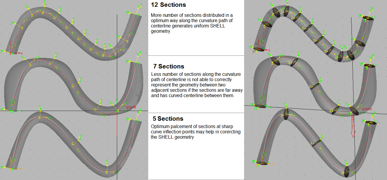
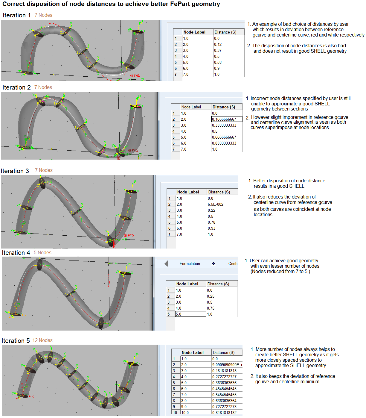
Note: | Depending on the shape of the centerline, to achieve proper extruded geometry it may require that care be taken when selecting the number and location of FE Part nodes even in circumstances where the node set is sufficient to achieve a centerline matching that of the reference curve. See below for examples of such node refinement for extruded geometry: |
External Geometry
The other option for geometry definition is to assign a piece of external geometry to the FE Part. Imported shell or Parasolid files are supported; when importing such files the reference marker must belong to the FE Part and be coincident with the node at S=0. Also, note that the Section properties will not automatically reflect the cross-sections of the imported geometry. You must manually specify the section properties at each node just the same as if you did not provide any geometry. As with all FE Parts, the calculation will assume that the cross-section centroid lies on the FE Part centerline. For rendering during animation the vertices of the external geometry are moved according to actual calculated positions of the centerline. External geometry that extends beyond the start and end nodes of the centerline will not deform but will move rigidly.
To add geometry that moves rigidly and per the motion of a particular FE Part marker one should attach a separate body (for example, rigid part) with its own geometry at that position.
Building within Adams Solver
Adams Solver only requires at a minimum that an FE Part be defined by node locations, corresponding section properties (area, area inertias) at each node location and, if contact is specified in the model, the geometry used for the contact force definition. The Adams Solver dataset can optionally contain information about other Adams View-generated objects (for example, sections). See the Adams Solver documentation on the FE_PART statement for more details.
It is expected that some users will choose to define FE Parts directly in the Adams Solver dataset (.adm file) with the minimal set of required information. If such datasets are imported into Adams View modification of the FE Part is not supported through the FE Part wizard. Even datasets exported from Adams View containing Adams View-created FE Parts will not be supported for modification through the FE Part Wizard if read back into Adams View. That Adams View database (.bin file) or Adams View command file (.cmd file) should be used for such purposes.
All Adams Solver analysis types are supported by the FE Part with the exception of system linear modes analysis via Adams Linear. This is not currently supported for models including FE Parts.
The FE Part supports shared-memory parallel (SMP) multi-threading. So, models with multiple FE Parts (3D Beam or 2D Beam types) or single large FE Parts (3D Beam type), in terms of the number of nodes, should exhibit performance improvements when setting the number of threads greater than one on multiple CPU/core machines.