Applying Preload
Upon creation, an FE Part can only represent its unloaded, un-deformed state because of its nonlinear nature, the preload specification for an FE Part is not as simple as applying a single scalar value like one would do for a linear spring, for example. The path by which an un-deformed, unloaded FE Part becomes deformed and loaded matters.
Generating a Preloaded FE Part
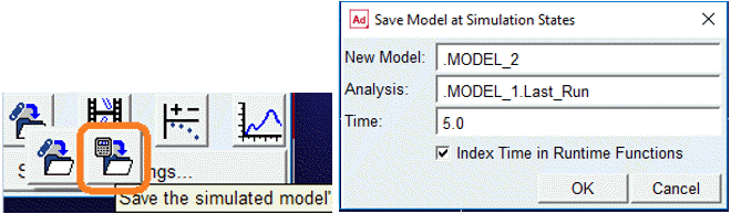
To specify a preload for an FE Part, you must begin with a model in which the FE Part is in its unloaded state. Then, you must model and simulate the loading event. After the loading event's simulation is complete, the Save Model at Simulated States capability can be used to create a new model whose design condition represents the end of the loading event's simulation (or any output time step of it, for that matter). This new model will have the FE Part in a preloaded configuration. The “Save the simulated model” button and "Save Model at Simulated States" dialog box shown below.
If the model contains 'n' numbers of FE Parts then this action will generate:
■'n' number of preload (.mtx) files each corresponding to one FE Part
■A new model that has the FE Part(s) in deformed and preloaded state
■The FE Part(s) will now reference their preload (.mtx) files
■In ensuing simulations of the new model, the FE Part(s) will behaviour will reflect their preloaded conditions
Note: | The new FE Parts will be limited in terms of what can be modified because changing some things, for example, node location/orientation and sections, would invalidate the preload definition. |
FE PART Preload Matrix File
The FE PART preload matrix files contains all state information of the FE PART at the time of the simulation in order for Solver to return the FE PART to its deformed configuration. This file not to be modified by the user. Any changes to this file will result in incorrect physics of the FE PART preload.
The preload file is in ADAMSMAT Data file format. The format specifications of ADAMSMAT explained in the Matrices section. This section provides more details of the preload file specific to FE PART.
The preload example file shown below:
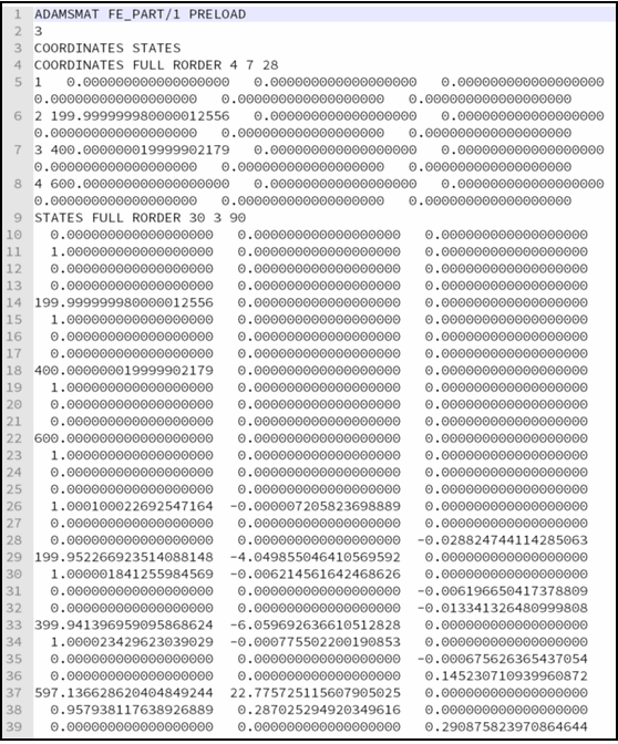
The first line of the preload matrix file includes the FE_PART id (1) for reference. The second line species the number of elements in the preload (3). The third line contains the name of each matrix in the file. There are two matrices, COORDINATES and STATES for FE Part preload file.
Next is the COORDINATES matrix which contains the node id and the undeformed coordinates (6) of each node with respect to the LPRF of the FE_PART. In the example there are 4 nodes defining the FE_PART. The STATES matrix contains all of the internal states of the FE_PART at the deformed configuration, including velocity states. This amounts to two states for each DOF of the FE_PART. For this example, the FE_PART is a 3DBeam with 4 nodes, for a total of 45 DOF and 90 entries. To determine the number of DOF for an FE_PART, refer Building FE Parts section.