Export FMU for SIMulation Workbench®
If you have not followed the steps mentioned in the 'Evaluate the Fixed Step Integrator' section and don't have the realtime_shared/sedan_rwd model opened in your Adams Car session, follow the steps 1-4 from the Evaluate the Fixed Step Integrator section to open the vehicle model.
Now you can move on with Exporting the FMU for SIMulation Workbench.
Generating an FMU for a Real Time Analysis is based on an FMU Definition Property file (.fmd). The FMU Property file approach simplifies the steps required for preparing FMU's of any of your vehicle assemblies for a particular Real Time application.
This approach assumes that the FMU in- and output signals are created in subsystems which can be added to your assembly on the fly when generating the FMU. In addition, model reduction methods can be applied to improve the model efficiency for the real time performance, such as removing sensors, switch parts, interface parts and dummy parts.
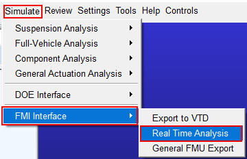
Once you have an assembly available in Adams Car (for example, the Real Time shared assembly: File → Open → Assembly → Right Click → Search → <realtime_shared>/assemblies.tbl → sedan_rwd.asy), and the Controls plugin (Tools → Plugin Manager) has been loaded, the 'Real Time Analysis' menu item can be selected for creating the FMU:
Clicking on this menu item will populate the FMU Export dialog, in which the FMU property file can be selected. A number of .fmd roperty files are available in the realtime_shared database:
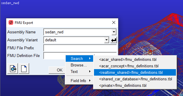
These property files are:
■simwb_generic_fmu_prop.fmd, for a FMU with an openloop controlled vehicle that can run at Simulation WorkBench.
■scalexio_generic_fmu_prop.fmd, for gerating an FMU to be used with the Scalexio realtime platform.
■rFpro_fmu_prop.fmd, for generating a SIMulation Workbench FMU supporting the interface to rFpro using the fmu road interface (road height information is passed via the fmu interface).
■rFpro_simwb_v2.fmd, for generating an FMU to be used at SIMulation Workbench in combination with rFpro without the fmu road interface.
■vi-drivesim.fmd, for generating a SIMulation Workbench FMU to applied in the Vi-Grade Simulator.
By clicking 'OK' or 'Apply' an FMU of the active model will be generated with the specification described in the FMU property file and stored in your working directory.
When clicking on the  icon, the FMU property file will be loaded in the FMU property file editor:
icon, the FMU property file will be loaded in the FMU property file editor: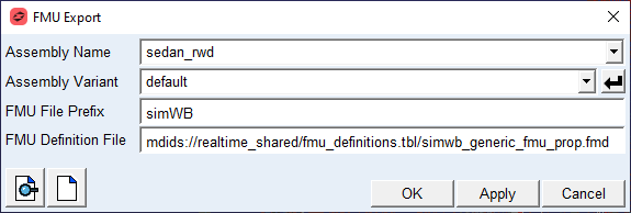
The following dialog will be populated:
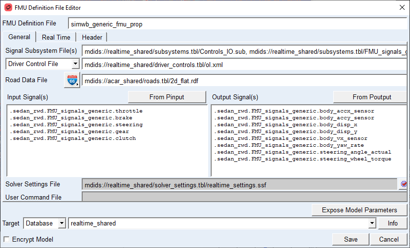
Note that the subsystems mentioned under 'Signal SubSystem File(s)' are added to your active vehicle assembly, so that the Input and Output Signals can be modified. The subsystems will be unloaded when exiting the editor.
If no FMU property file name has been specified, a new FMU property file can generated from scratch.
In this approach it is strongly recommended to have the Input and Output signals created by the subsystems so that the FMU property file is not dependent on the assembly. In the property file the name of the assembly is not mentioned.
For the FMU a 'Driver Control File' or an 'Event Set File' needs to be specified. In case of a 'Driver Control File', a 'File Driven Event' will be created with the 'Road Data File' when exporting the FMU.
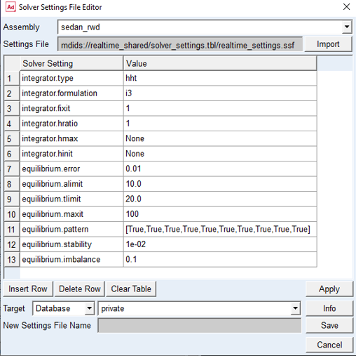
Further the General Tab allows you to specify the Solver Settings by means of a 'Solver Setting File', for a Real Time FMU the 'Fixed Step Solver' needs to be selected:
A 'User Command File' can be specified, that will be executed just before generating the FMU.
The 'FMU Prefix' is the prefix added to the FMU file name.
Also dynamic FMU parameters can be added to the FMU with by 'Expose Model Parameters' button.
Target, Directory or Database defines the save location of the FMU Property file.
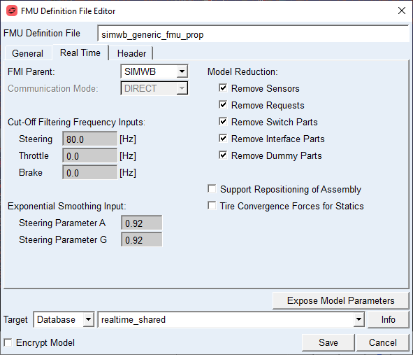
Within the 'Real Time' tab additional real time specific attributes can be defined:
■Communication Mode', depends on the application, that is, DIRECT for SimWB, TCP/IP for SCALEXIO, PIPE for an ADAMS parent-child simulation.
■'Real Time Environment', specifies the MSC_ADAMS_REAL_TIME environment variable for the model. However, this setting can be overwritten in the Real Time application as well, for detail see, Adams Solver Advanced Settings. 'Default' means MSC_ADAMS_REAL_TIME = 'ON'
■For creating most efficient fmu model 'Model Reduction' features can be switched on. For an open loop controlled vehicle FMU, no sensors are required. Furthermore removing Switch Parts, Interface Parts and Dummy Parts will benefit the Real Time Index even more.
■Note that removing Requests will not effect solver speed, because requests are not active during real time operation, however it may reduce the FMU model size.
■Cut-Off Filtering Frequency Inputs:
When the signal subsystems have the pvs_cut_off_steering, pvs_cut_off_steering, pvs_cut_off_steering available (like in the Controls_IO.sub), these low pass filter settings can be adjusted.
■Exponential Smoothing Input
Exponential smoothing will be applied if the signal subsystems have the pvs_smooth_steering_a and pvs_smooth_steering_b defined
■Support Repositioning of Assembly
Will allow to reposition the Vehicle with respect to the road using the VIDRIVESIM_VEHICLE_USER_LOCATION and the VIDRIVESIM_VEHICLE_USER_ORIENTATION environment variables.
Will allow to reposition the Vehicle with respect to the road using the VIDRIVESIM_VEHICLE_USER_LOCATION and the VIDRIVESIM_VEHICLE_USER_ORIENTATION environment variables.
■Tire Convergence Forces for Statics, will improve statics convergence conditions for Adams Solver.
Example FMU property file:
$---------------------------------------------------------------------MDI_HEADER
[MDI_HEADER]
FILE_TYPE = 'fmd'
FILE_VERSION = 1.0
FILE_FORMAT = 'ASCII'
(COMMENTS)
{comment_string}
'FMU property file on Simulation WorkBench, general use'
$-----------------------------------------------------------------FMU_DEFINITION
[FMU_DEFINITION]
SIGNAL_SUBSYSTEMS = 'mdids://realtime_shared/subsystems.tbl/Controls_IO.sub, mdids://realtime_shared/subsystems.tbl/FMU_signals_generic.sub'
!
DCF_FILE = 'mdids://realtime_shared/driver_controls.tbl/ol.xml'
ROAD_INTERFACE = 'mdids://acar_shared/roads.tbl/2d_flat.rdf'
!
!removes items that are not required
REMOVE_SENSORS = 'YES'
REMOVE_REQUESTS = 'YES'
REMOVE_SWITCH_PARTS = 'YES'
REMOVE_INTERFACE_PARTS = 'YES'
REMOVE_DUMMY_PARTS = 'YES'
!
ENCRYPT_MODEL = 'NO'
!
EXPOSE_VARIANT = 'NO'
EXPOSE_EVENT = 'NO'
!
!script to run after adding the templates, but before generating the fmu
USER_CMD_SCRIPT = ''
!
!removes all items added for generating the fmu
CLEAN_UP_MODEL = 'YES'
VERBOSE = 'NO'
!
$-----------------------------------------------------------------------FILTERS
[FILTER_SETTINGS]
STEERING_FILTER_FREQ = 80.0
BRAKING_FILTER_FREQ = 40.0
THROTTLE_FILTER_FREQ = 40.0
$---------------------------------------------------------------------SMOOTHING
[EXPONENTIAL_SMOOTHING]
STEERING_PARAMETER_A = 0.92
STEERING_PARAMETER_G = 0.92
$------------------------------------------------------------------------SOLVER
[SOLVER_SETTINGS]
SOLVER_SETTINGS = 'mdids://realtime_shared/solver_settings.tbl/realtime_settings.ssf'
$------------------------------------------------------------------------SOLVER
[FMU_SETTINGS]
COMMUNICATION_MODE = 'DIRECT'
$------------------------------------------------------------------------INPUTS
[PLANT_INPUTS]
FMU_signals_generic.throttle
FMU_signals_generic.brake
FMU_signals_generic.steering
FMU_signals_generic.gear
FMU_signals_generic.clutch
$------------------------------------------------------------------------OUTPUTS
[PLANT_OUTPUTS]
FMU_signals_generic.body_accx_sensor
FMU_signals_generic.body_accy_sensor
FMU_signals_generic.body_disp_x
FMU_signals_generic.body_disp_y
FMU_signals_generic.body_vx_sensor
FMU_signals_generic.body_yaw_rate
FMU_signals_generic.steering_angle_actual
FMU_signals_generic.steering_wheel_torque
Signal Subsystem templates
The Adams distribution contains four new (signal) templates that support FMU generation of the Vi-Grade Simulator, running rFpro or a generic Adams FMU at SIMulation Workbench. These templates are stored in /realtime/realtime_shared.cdb/templates, more details:
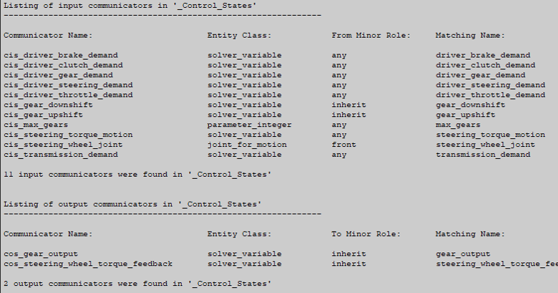
■_Control_States.tpl, a generic template that arranges the input to the model (steering, brake, throttle, gear and clutch) in case of an open loop vehicle control by the FMU inputs. This template is used in the Controls_IO.sub subsystem. It also offers the filtering of the steering, throttle and brake input signals to the model with the pvs_cut_off_steering, pvs_cut_off_brake and pvs_cut_off_throttle parameters. This template communicates to the model on one hand and the signal subsystem template (as below) on the other hand. The in- and output communicators are:
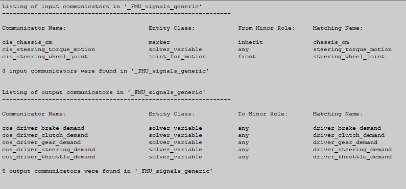
■_FMU_signals_generic.tpl, a generic signal template for running an fmu at SIMulation Workbench. The output signals provide information of the vehicle body and steering wheel torque. The used communicators are:
■_rFpro_simwb.tpl, a template that the creates the in- and output signals for the use of rFpro in combination with Simulation Workbench, the communicators used in this template are:
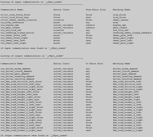
Note that the FMU road interface is used in this template, it allows to use the FMI interface for supplying the road height and friction information. For supporting this, the special _handling_tire_fmu_road.tpl (with additional communicators) is used in the realtime_shared model assembly. The road data file to be selected for this interface is mdids://acar_shared/roads.tbl/fmu_road.rdf.
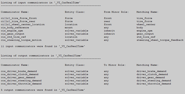
■_VI_CarRealTime.tpl, a signal template for the VI-Grade simulator, signals in the VI_CarRealTime class, using these communicators:
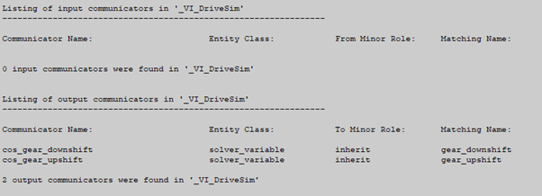
■_VI_DriveSim.tpl, a signal template for the VI-Grade simulator, signals in the VI_DriveSim class, using these communicators:
Notes: | ■For using the Real Time Animation the 'Real Time Animation' needs to be set to 'On', see also Getting Started Adams Real Time Animation. ■Running this FMU on a real time platform parent-child simulation, the event will finish once the abortTime, as defined in event file sim_throttle_brake_steerang.xml, is reached. You can prevent this by increasing parameter abortTime="10000" in the .xml event file. ■Selecting the "SIMulation Workbench" option in Real Time FMI Parent performs a 0.05 seconds initial simulation before the real time simulation. This will allow time for initialization purposes and prevents overruns at the startup of the real time simulation. ■The stepSize parameter defined in the .xml event file "sim_throttle_brake_steerang.xml" (section "dcf:DcfMini") determines the maximum Adams Solver time step of the real time simulation. If the step size in your real time application (that is, the fixed step integrator's step size as determined by HRATIO and the output sampling rate) is set to a larger value than the stepSize parameter in the .xml event file, the Adams Solver time step will be limited to the stepSize parameter in the .xml event file. ■Because the "DIRECT" communication option is automatically set when the SIMulation Workbench option is selected, this FMU cannot be used for "Adams-to-Adams" FMI co-simulations. However, performing such a co-simulation prior to moving to the real time environment is a good idea to verify the integrity of the model, event, and FMU export process. Steps to do this are not included directly here but can be found in the Appendix: Offline Verification via Adams-Adams Co-Sim of this document. For those interested, go to the Appendix now and perform those steps then proceed with the next section below. ■Did you know? Adams Controls supports heterogeneous FMU export. That is, an FMU exported from an Adams session on one operating system can be used in a co-simulation on another. |