Building the Pivot and Handle
As the initial steps in building the latch model, you perform the following tasks:
Starting Adams View and Creating a Database
In this section, you start Adams View and create a modeling database containing a new model named Latch. A modeling database contains all your work in the current session of Adams View. It contains any models you create, their attributes, simulation results, plots, customized menus and dialog boxes, and any preferences you set.
In the Linux environment you start Adams View from the Adams Toolbar. In the Windows environment you start Adams View from the Start button.
To start Adams View in the Linux environment:
1. At the command prompt, enter the command to start the Adams Toolbar, and then press Enter. The standard command that MSC Software provides is adamsx, where x is the version number, for example adams2024_1.
The Adams Toolbar appears.
2. Select the Adams View tool  .
.
.The Welcome dialog box appears on top of the Adams View main window.
To start Adams View in the Windows environment:
1. Select Start.
2. Point to Programs, point to Adams 2024.1, and then select Adams View.
The Welcome dialog box appears.
To create a database from the Welcome dialog box:
1. Select Create a new model.
2. Replace the contents of the Model name text box with Latch.
3. Select OK.
Familiarizing Yourself with Adams View
Before continuing with the tutorial, familiarize yourself with the Adams View interface. In particular, ribbon based tabbed icon containers, see section Ribbon Capability for more information.
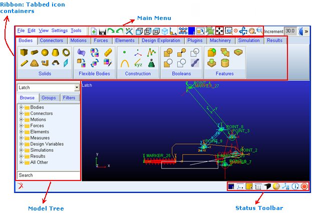
Figure 2 Adams View interface
Learning About Getting Help
When working in Adams View, you can get help in a number of ways:
■Use the online help to read overviews, procedures, and see many examples. From the Help menu, select Adams View Help.
■Use the dialog box help to learn about entering values in a dialog box or using an Adams View tool. While working in a dialog box, press the F1 key.
For more information about getting help in Adams View, see the printed Release Guide that comes with your license.
Setting Up Your Work Environment
In this section you set your units, specify the grid size, and display the coordinate window. You can change the units at any time during the modeling process, even while reading and writing model or results data files. You can use the Adams View working grid and the coordinate window to establish map points and receive feedback on precise locations for the design layout.
To set up your work environment:
1. From the Settings menu, select Units.
The Units Settings dialog box appears.
2. Set the units of length to centimeter.
3. Select OK.
4. From the Settings menu, select Working Grid.
The Working Grid Settings dialog box appears.
5. Set the grid size along X and Y to 25, and the grid spacing for X and Y to 1
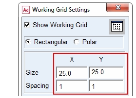
Note: | You do not need to enter units because Adams View uses the default units if you do not specify them. However, because you set the units to centimeters earlier, ensure that you do not enter mm after the values in the Size and Spacing text boxes. |
6. Select OK.
7. From the Settings menu, select Icons.
The Icon Settings dialog box appears.
8. In the New Size text box, enter 1.5.
Note: | The text box New Size is colored gray. Throughout Adams View gray text boxes means that the text box is optional and you do not have to enter a value to execute the command. |
9. Near the bottom of the Icon Settings dialog box set Name Visibility to On.
10. Select OK.
To display the Coordinates window:
1. From the View menu, select Coordinate Window.
The Coordinates window appears.
2. Move your cursor around the screen and notice the coordinate location labels that appear in the Coordinates window and next to the cursor.
During this tutorial, you will find it very helpful to have the Coordinates window open because you will place many objects based on their coordinate location.
Creating Design Points
Adams View enables you to change the layout of your design to quickly find the best mechanism for the application. You use points to lay out your design so that you can make layout changes by moving the points. Points are used to define locations in space on which you can position and parameterize other objects. Points are the easiest way to parameterize the geometry of a model because they let you specify important locations once and build other modeling objects from them. Parameterization becomes important later on when you work on refining your latch model.
To create design points:
1. From the Main menu, select the Dynamic Pick tool  to zoom in on your grid.
to zoom in on your grid. 2. Drag the cursor across the area of the working grid display.
3. Click the Bodies tab on the Adams View ribbon.
4. From the Construction container, click the Point tool  and click the locations shown in Table 1 to place design points. Use the default settings for point, which are Add to Ground and Don’t Attach.
and click the locations shown in Table 1 to place design points. Use the default settings for point, which are Add to Ground and Don’t Attach.Note: | To create multiple points without having to select the Point tool again, double-click the tool. To deselect the Point tool, select the Select tool. |
X location: | Y location: | Z location: | |
|---|---|---|---|
POINT_1 | 0 | 0 | 0 |
POINT_2 | 3 | 3 | 0 |
POINT_3 | 2 | 8 | 0 |
POINT_4 | -10 | 22 | 0 |
Creating the Pivot
Create the pivot using the Plate tool. The pivot represents the pivot part, as shown in Figure 1.
To create the pivot:
1. Click the Bodies tab on the Adams View ribbon.
2. From the Solids container, click the Plate tool  .
.
. 3. In the Main toolbox, in the Thickness text box, enter 1, and then press Enter.
Note: | Pressing Enter every time you enter text into a text box ensures that Adams View accepts the entered value. |
4. In the Radius text box, enter 1, and then press Enter.
5. Click the location of POINT_1, POINT_2, and POINT_3.
Note: | The Adams View status bar provides instructions on how to perform operations. When you move your cursor on the screen during an operation, the status bar displays what you should do next. The status bar is located below the Adams View main window. For the location of the status bar, see Figure 1. |
6. Right-click to stop selecting points and create the pivot geometry.
Renaming the Pivot
As you create objects, Adams View automatically assigns names to them. Each name consists of a string containing the object type and a unique integer ID for that type. For example, Adams View named the recently created part PART_2.
The full name of an object is comprised of the concatenated names of its parent similar to a directory structure in a file system. Because PART_2 is located within the model named Latch, its full name is .Latch.PART_2, while the full name of the marker named cm on PART_2 is .Latch.PART_2.cm.
In this section, you rename PART_2 to pivot. Adams View understands that you are just renaming the part, so the model name Latch remains.
To rename the pivot:
1. Right-click the plate part.
A shortcut menu appears.
2. Point to Part: PART_2, and then select Rename.
The Rename Object dialog box appears.
3. Replace PART_2 with pivot, as shown in the following dialog box:
Creating the Handle
You can create the handle using the Link tool  .
.
.To create the handle:
1. Click the Bodies tab on the Adams View ribbon.
2. From the Solids container, select the Link tool  .
.
. 3. Click POINT_3, then POINT_4 to create a link between the two points. 
Note: | Only attach the link to a point when that point label is visible. |
4. Rename the link part, Part: PART_3, to handle, to represent the handle part as shown in Figure 1.
Connecting the Parts Using Revolute Joints
A revolute joint is an attachment between two parts that allows one part to move with respect to another part about a common axis.
In this section, you place a revolute joint between the pivot and ground, which will allow the pivot to rotate with respect to ground. You also place a second revolute joint between the pivot and handle to allow the two parts to rotate with respect to each other.
You will use the construction method 2 Bod - 1 Loc, and Normal To Grid to create the revolute joints, which is the default method. When you use this method for creating revolute joints, you select the two bodies to attach and then select the location.
To connect the parts using revolute joints:
1. Click the Connectors tab on the Adams View ribbon.
2. From the Joints container, select the Revolute Joint tool  .
.
. 3. To select the parts to attach, click the pivot and ground (the background).
4. Click POINT_1 to set the joint’s location.
The revolute joint at POINT_1 should look like this:
Note: | If you did not change the icon size as explained in Step 7. in Setting Up Your Work Environment, you will not see the revolute joint on the screen. Go back and change the icon size as explained in Step 7. In the Icon Settings dialog box, be careful not to accidentally turn off the display of icons. |
5. Select the Revolute Joint tool again.
6. Select the pivot, the handle, and POINT_3.
Simulating the Motion of Your Model
In this section you set the simulation parameters, and simulate the motion of the model to see if you have assembled the parts and joints properly. You set the simulation end time and the number of output steps to tell Adams View how long you want the simulation to run, and the frequency with which you want it to output the data.
During the simulation, the handle moves in a circular motion with respect to the pivot, as the pivot moves in a circular motion with respect to ground. Note that gravity is acting on the model.
To simulate the motion of your model:
1. Click the Simulation tab on the Adams View ribbon.
2. From the Simulate container, click the Simulate tool  .
.
. 3. Set up a simulation with an end time of 1 second and 50 steps.
4. Select the Simulation Start tool .
.
. The model simulates, and then remains in simulate mode.
5. To return to the initial model configuration, select the Reset tool  .
.
.At this step in the creation of the latch, the model is effectively a double pendulum falling due to the influence of gravity. This illustrates one of the advantages of interactive model building. Namely, that you can interrogate the behavior of the model even though the model is not complete.
Seeing the Effect of Parameterization
Since you parameterized your latch model using points, you can move a point and the related objects update automatically. For example, if you move POINT_1, the pivot and the joint move along with it since they were created on top of that point.
To see the effect of parameterization:
1. Right-click POINT_1.
A shortcut menu appears.
2. Point to Point: POINT_1, and then select Modify.
The Table Editor appears, listing the points in your model and their locations.
3. Set the x location for POINT_1 to -2.
4. Near the top right corner of the Table Editor, select Apply.
POINT_1, along with the joint and the pivot, move to the new location.
Note: | You can move the Table Editor out of the way by clicking and dragging its top window border. |
5. Set the x location for POINT_1 back to 0.
6. Select OK.