Creating Flexible Bodies from Existing Solid Geometry
ViewFlex lets you generate a flexible body from existing solid geometry that defines a rigid part of a model. You can either create this geometry in your Adams product or import it from an external CAD source:
You can use all types of solid primitive geometry (the geometry must have volume) or Parasolid geometry.
Shell geometry can be meshed using shell tria elements only.
If you would like to use multiple pieces of geometry to define a flexible body you must first use Boolean operations to combine them. If imported geometry represented within Adams as a single geometry entity contains multiple closed volumes, then it will need to be modified external to Adams (for example, in the originating CAD software).
You can set all the options for mesh properties, attachments, and secondary nodes or let ViewFlex automatically create the flexible body for you.
Learn more:
Accessing the Geometry Method Options
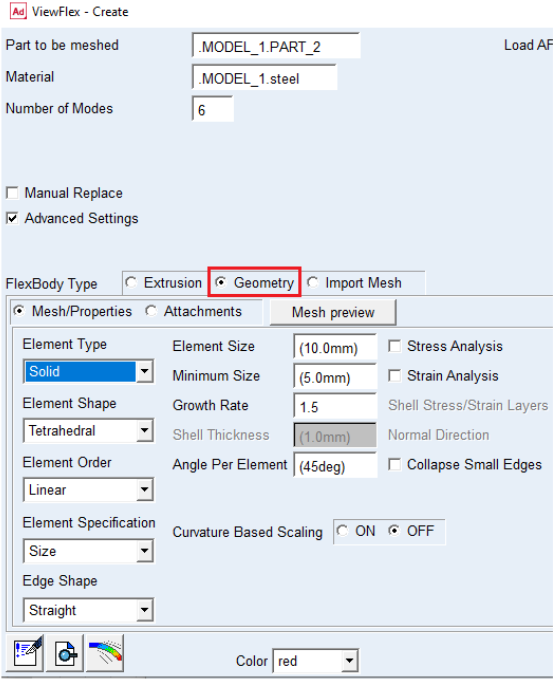
To access the Geometry Method options:
■In the ViewFlex dialog box, set FlexBody Type to Geometry.
In the Geometry Method the ViewFlex dialog box offers different options than in the Extrusion Method. In the upper part of the window you can select the existing geometry, whereas the lower section is for defining the mesh properties.
Selecting the Rigid Body
Applying the geometry method, you can define a flexible body starting from a rigid body entirely composed using Adams View's modeling capabilities, or imported from an external Parasolid file format.
Note: | You can only mesh a complete rigid body defined by unique geometry (through appropriate use of the embedded Boolean operations). |
For shell geometry, you can only use shell elements for meshing.
To select the existing solid geometry to use for the flexible body:
In the Part to be meshed text box, enter a rigid body. Right-click to select the geometry from the screen or browse for it in the Database Navigator.
Automatically Creating and Swapping Flexible Bodies
ViewFlex can be used to create a flexible body automatically as well as to replace a selected rigid body.
To replace a rigid body ViewFlex performs the following steps:
1. Create a temporary mesh based on default mesh properties.
2. Find attachments based on the location of joints and forces that are applied to the rigid body.
3. Find the closest secondary nodes of the temporary mesh to each attachments and connect them through rigid bars.
4. Create the flexible body.
5. Apply the joints and forces at the attachment points of the flexible body.
6. Deactivate the rigid body.
To automatically create a flexible body:
1. After selecting the geometry of the rigid body as explained in Selecting the Rigid Body, at the top of the ViewFlex dialog box, select Manual Replace (see figure below).
2. Click OK.
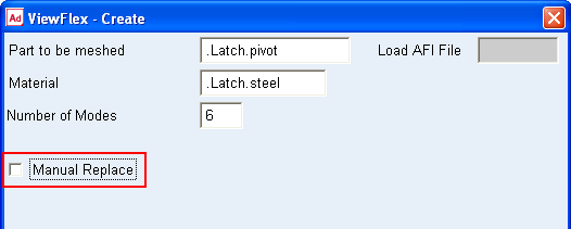
Notes: | ■Manual Replace = Off : Viewflex will automatically replace the part with flexible body by transferring all connections from rigid body to flexible body. This will deactivate the rigid part and make it invisible. ■Manual Replace = On: Viewflex will not automatically replace the part and both rigid and flexible body will be shown. You need to manually create the connections on the flexible body. |
Creating Flexible Bodies by Setting Standard Options
As an alternative to the automatic creation of a flexible body in the Geometry Method, mesh properties can be set manually. Subsequently attachment points and secondary nodes can be defined, as shown in Defining Attachment Points. Additionally the mesh can be previewed.
Setting Mesh Properties
To set mesh properties for flexible bodies in the Geometry Method:
1. If necessary, select Mesh/Properties.
2. From the Element Type list, select from the following Element types:
a. Solid: Creates solid elements.
b. Shell: Creates shell elements.
Note: | As you are working with a shell, you must enter an appropriate value in the Shell Thickness text box. |
3. From the Element Shape list, select from the following Element shapes:
The following Element shapes appear when Solid Element Type is selected
a. Tetrahedral: Creates tetrahedral solid elements.
The following Element shapes appear when Shell Element Type is selected
a. Triangle: Creates triangular shell elements.
b. Quadrilateral: Creates quadrilateral shell elements.
4. From the Element Order list, specify either:
a. Linear: Sets linear element order for first-order elements.
b. Quadratic: Sets quadratic for second-order elements.
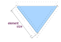
5. From the Element Specification list, select how to define the element size:
a. Auto: Uses an automatic scale factor to determine the element size based on the selected part's dimensions.
b. Size: After entering the average edge length of the element, ViewFlex asks you to input the element's median and minimum side size (using automatic mesh refining, where required by the geometry to mesh).
6. From the Edge Shape list, select how to define the element shape. The options indicates whether higher order element should be generated with straight or curved boundary edges.
■Straight: All mid-side nodes will be positioned at the average coordinate of the end nodes.
■Curved: Mid-side nodes on boundary geometry will be projected onto the geometry resulting in curved element edges.
■Mixed: Edges will be curved except when such curving would result in an invalid element (negative Jacobian).
7. Element Size
■Enter the average edge length of the element. This option will be available upon selecting “Size” from Element Specification options.
8. Minimum Size
■Absolute minimum element size. The mesh generator uses this size to cap off the refinement when doing curvature based refinement. If the curvature factor specifies a element edge length which is smaller than the minimum element size, the edge length is capped off by using the minimum element size. This avoids over refinement in areas of high curvatures.
9. Growth Rate
■This is a mesh parameter to control the rate of size transition between adjacent elements. It is the desired maximum length ratio between 2 adjacent tetrahedral edges. This parameter is mainly used to produce coarser elements in the interior of a solid and reduce the number of tet-elements on the solid. When meshing a solid with curvy faces, the tet-elements on the solid faces have to follow the shape of geometry of the surfaces, and their sizes are generally small. If the growth rate is close to 1.0, the small mesh sizes will be propagated from the solid boundary to the interior of solid and the number of elements may be very big; if the growth rate is bigger, the mesh size will increase gradually from the solid boundary to the interior of solid, as a result, the number of elements will be reduced.
10. Shell Thickness
■Enter the thickness of shell elements for computing mass and stiffness properties.
11. Angle Per Element
■The parameter "angle-per-element" is a curvature-based mesh size control parameter which is the max-allowed subtended angle of an element-edge on a curved surface. It is used to define local mesh density at each point of a surface.
■For a point P on a curved surface, we use the following way to define subtended angle of an element-edge E in the neighborhood of P and define local mesh density at the point P:
♦First, we calculate the principal curvatures at the point P. Then use the reciprocal of the max principle curvature as radius and the center of max principle curvature as center to define an osculating circle that passes through the point P. The element-edge E is considered a chord of the osculating circle. The subtended angle of element-edge E is defined as the subtended angle of the chord from the center of the circle.
♦The local mesh density D at P is calculated as the length of the chord whose subtended angle = angle-per-element. The length of an element-edge in the neighborhood of P should be equal or smaller than the local mesh density D. If angel-per-element is fixed, the local mesh density D is inversely proportional to the max principal curvature at P; if max principal curvature is fixed, the local density D increases as angle-per-element increases.
Example: If angle-per-element = 30 degree and there is a circular hole of a surface, we expect that at least 12 (=360/30) element-edges along the hole.
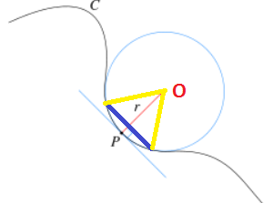
Where:
■P: a point on surface, Circle: the osculating circle, C: a curve on a surface, O: the center of osculating circle, r: the radius of the osculating circle which = 1.0/mpc, where mpc is the max principle curvature at point P.
■Blue line segment E: An element-edge in the neighborhood of P.
■Yellow line segment: Connecting an end point of the E to the center of osculating circle
The subtended angle of element-edge E is the angle formed by two yellow-line-segments. It is controlled by angle-per-element
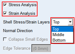
12. Stress/Strain Analysis
A stress and/or strain calculation can be run/executed during the creation of a flexible body.
■Shell Stress/Strain Layers
♦Top
♦Middle
♦Bottom
■Normal Direction
♦X
♦Y
♦Z
♦-X
♦-Y
♦-Z
13. Collapse small edges:
If checked small edges or features will collapse to zero in meshing.
14. MSN Based Refinement: ON or OFF
This should be applied only when you are doing quadratic meshing or edge shaped is not straight (curved or mixed).
When set to ON, the mesh generator will perform automatic refinement of the mesh as required to keep the location of mid-side nodes on curved boundaries within acceptable limits relative to the corner node locations. Refinement will occur if one of the following is true:
♦The distance between the curved mid-side node location and the straight line mid-point between the corner nodes is more than 1/4 the distance between the corner nodes.
♦The mid-side node location approaches the 1/4 or 3/4 points of the straight line connecting the corner nodes.
When set to OFF, no refinement will occur based on mid-side node locations.
15. Curvature Based Scaling: ON or OFF
When this option is ON the mesher uses the geometry (curve or surface) curvature to automatically provide mesh grading and smoother mesh transition. The mesh will be more uniform if this option is turned OFF as no grading is done.
16. Advanced Options: Rotate and translate the mesh to be generated. Advanced options are only available for Adams View shell geometry. The advanced options are explained and shown below.
i. X translation: X global position
ii. Y translation: Y global position
iii.Z translation: Z global position
iv. X rotation: X global orientation
v. Y rotation: Y global orientation
vi. Z rotation: Z global orientation
Selecting "Get from Model" fills the text boxes with the current location and orientation of the selected geometry automatically.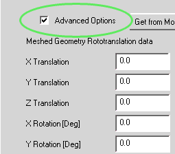
17. Manual Replace: It will help you to automatically create flexible body.
■Manual Replace = Off : Viewflex will automatically replace the part with flexible body by transferring all connections from rigid body to flexible body. This will deactivate the rigid part and make it invisible.
■Manual Replace = On: Viewflex will not automatically replace the part and both rigid and flexible body will be shown. You need to manually create the connections on the flexible body.
Previewing a Mesh
To preview a mesh of the selected geometry in the Geometry Method:
■Select Mesh Preview.
ViewFlex generates a preview of the meshed solid part with the selected parameters.
After mesh preview generation, Del Mesh Preview is automatically selected, so you can delete the previously generated mesh, if it does not look according to your wishes and/or you want to change its properties.
You can see the steps that ViewFlex performs to create the mesh in the Message window:
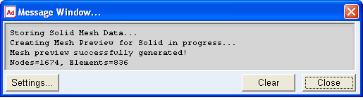
After generating the mesh, the attachment container appears so you can select the attachment points. The Mesh/Properties container is not editable until you clear the selection of Delete Mesh Preview and select to not delete the mesh. In addition, the FlexBody preview button is selected, which allows you to generate the full mesh of the flexible body (including primary nodes and their connections to secondary nodes), without performing a modal calculation.
Activate Stress/Strain Calculation
A stress and/or strain calculation can be run/executed during the creation of a flexible body using the Geometry Method. It is available for both shell and solid elements. For shell elements, you can define the surface (top, middle, bottom) on which you want the stress/strain calculated.
Note: | Adams Durability is a prerequisite for the stress calculation in Adams Postprocessor. |
To calculate the stress/strain:
■While defining the mesh and material properties from the ViewFlex dialog box, select Stress Analysis and/or Strain Analysis as shown below.
■For shell elements select the layer on which you want the stress/strain calculated (top, middle, bottom).