atrike_shared database
Dive/Anti-dive Link suspension
Overview
Dive/Anti dive link suspension design is commonly used in the three-wheelers front steerable suspension. It is used along with steering of fork type. It uses single or dual suspension links along with spring and damper element. The damper top mount is connected to the steering fork and the lower mount to the dive link.
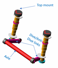
Figure 97 Dive/Anti dive link suspension
Template name
_tri_link_suspension
Major role
Suspension
Application
Suspension and full-vehicle assemblies of delta type trike vehicle.
Description
Dive/Antidive link suspension is the widely used suspension in Delta type of trike vehicle. You can use the template as a front steerable suspension.
One end of the suspension link is attached to the axle, which carriers the wheel part and the other end is connected to the steering fork.
Based on the pivot position of the link, the suspension acts as dive or anti-dive link suspension.
Spring and damper are connected between the suspension links and the steering fork.
All the bushing elements are modelled as connectors.
Files referenced
Bushings, springs, dampers, bumpstops and reboundstops property files
Topology
The tri_link_suspension template represents a standard design employing suspension dive/ anti dive links and an axle. One end of the suspension link is attached to the axle, which carriers the wheel part and the other end is connected to the steering fork.
The following table lists the topological information of tri_link_suspension.
The joint: | Connects the part: | To the part: |
|---|---|---|
cnl_fork_to_link | gel_susp_link | mts_str_fork |
cnl_bottom_mount | gel_lower_strut | gel_susp_link |
cnl_susp_link_to_axle | gel_susp_link | ges_axle |
jklhoo_top_mount_kinematic | gel_upper_strut | mts_str_fork |
The following table details the design option & topologies for suspension link type configuration options.
Design Option | The connector: | Connects the part: | To the part: |
|---|---|---|---|
Single link suspension- configuration 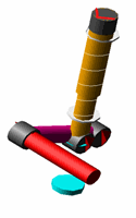 | cns_susp_link_to_axle | ges_susp_link | ges_axle |
cns_bottom_mount | ges_lower_strut | ges_susp_link | |
cns_fork_to_link | ges_lca_link_2 | mts_str_fork | |
Dual link suspension- configuration 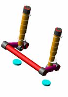 | cnl_susp_link_to_axle | gel_susp_link | ges_axle |
cnl_bottom_mount | gel_lower_strut | gel_susp_link | |
cnl_fork_to_link | gel_lca_link_2 | mts_str_fork |
Parameters
The following table lists the parameters in the templates.
The parameter: | Takes the value: | Its units are: |
|---|---|---|
pvs_toe_angle | Real | Degrees |
pvs_camber_angle | Real | Degrees |
pvs_suspension_link_type | Integer | No units |
Toe and camber variables in the template define the wheel spin axis.
Suspension_link_type variable helps to select single or dual link suspension.
Communicators
Mount parts provide the connectivity from the template to the body and steering subsystems. Output communicators publish toe, camber, steer axis, and wheel-center location information to the appropriate subsystems and test rig. The following table lists the input and output communicators in the template.
The communicator: | Belongs to the class: | Has the role: |
|---|---|---|
ci[lr]_strut_to_body | mount | inherit |
cis_str_fork_loc_upper_bearing | location | inherit |
cis_str_fork | mount | inherit |
cis_str_fork_loc_lower_bearing | location | inherit |
co[lr]_camber_angle | parameter_real | inherit |
cos_suspension_mount | mount | inherit |
cos_suspension_upright | mount | inherit |
co[lr]_toe_angle | parameter_real | inherit |
cos_wheel_center | location | inherit |
cos_driveline_active | parameter_integer | inherit |
cos_suspension_parameters_ARRAY | array | inherit |
Steering Fork
Overview
Steering fork is commonly used in the Delta type of trike vehicle configuration. This fork is connected to suspension links and directly steers the wheel.
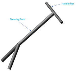
Figure 98 Steering fork
Template name
_tri_fork_steering
Major role
Steering
Application
Steering and full-vehicle assemblies of delta type trike vehicle.
Description
Handlebar or Steering wheel is attached to the steering fork. The revolute joint is used to connect the steering fork to body and suspension links. The orientation of revolute joint that connects between steering fork and body is the caster angle of the suspension.
Steering ratio is always set to 1, meaning steering wheel angle and road wheel angle are always the same.
Topology
The following table lists the topological information of tri_fork_steering.
The joint: | Connects the part: | To the part: |
|---|---|---|
josfix_fork_to_handlebar | ges_fork | ges_steering_wheel |
josrev_steering_wheel | ges_steering_wheel | mts_steering_column_to_body |
The following table details the topologies for suspension link type configuration options.
Design Option | The joint: | Connects the part: | To the part: |
|---|---|---|---|
Steering fork type- symmetric fork 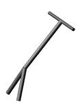 | josfix_fork_to_handlebar | ges_fork | ges_steering_wheel |
josrev_steering_wheel | ges_fork | mts_steering_column_to_body | |
Steering fork type- assymmetric fork 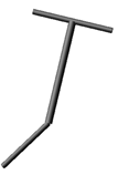 | josfix_fork_to_handlebar | ges_fork | ges_steering_wheel |
josrev_steering_wheel | ges_fork | mts_steering_column_to_body | |
Parameters
The following table lists the parameters in the templates.
The parameter: | Takes the value: | Its units are: |
|---|---|---|
pvs_max_steering_torque | Real | newton-mm |
pvs_max_steering_angle | Real | Degrees |
pvs_steering_fork | Integer | No units |
Communicators
Mount parts provide the connectivity from the template to the body subsystems and suspension. The following table lists the input and output communicators in the template.
The communicator: | Belongs to the class: | Has the role: |
|---|---|---|
cis_steering_column_to_body | mount | inherit |
cos_max_steering_angle | parameter_real | inherit |
cos_max_steering_torque | parameter_real | inherit |
cos_fork_to_susp_link | mount | inherit |
cos_steering_wheel_joint | mount | inherit |
Single Handling tire
Overview
This template “tri_handling_tire_single.tpl” has been derived from the existing “handling tire” template available in acar shared database.
The tri_handling_tire_single template has been created by removing existing left-right symmetry and by adding single type objects.
For more information, see Tire System.
Brake System_3Wdisk
Overview
This template “brake_system_3Wdisk” has been derived from the existing “brake_system_4Wdisk” template available in acar shared database.
The trike brake system template tri_brake_system_3Wdisk has been created by replacing front two discs with a single disk to support delta and tadpole type trike vehicle configuration.
For more information, see Disc-Brake System.
Powertrain System
Overview
This template has been derived from the existing “powertrain” template available in acar shared database.
The engine torque map in the existing template has been scaled down to suit the trike type vehicle.
For more information, see Powertrain System.
Rigid chassis
For more information, see Rigid Chassis.
Hotchkiss Suspension
For more information, see Hotchkiss Suspension.
Trailing arm Suspension
For more information, see Semi-Trailing Arm Advanced Suspension.
Swing arm Suspension
Overview
Swing arm suspension is commonly used as non-steerable rear suspension in Tadpole type trike vehicle. It holds the rear axle firmly, while pivoting to absorb bumps and suspension loads.
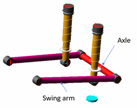
Figure 99 Swing arm suspension
Template name
_tri_tadpole_swing_arm_suspension_rear.tpl
Major role
Suspension
Application
Rear Suspension and Full vehicle assembly of Tadpole type trike vehicle.
Description
Swing arm suspension is the common suspension used for Tadpole type trike vehicle’s rear suspension.
The one end of the suspension link is attached to the axle, which carriers the wheel part and the other end is pivoted to frame.
Spring and damper are connected between the swing arm and the chassis.
All the bushing elements are modelled as connectors.
Topology
The following table lists the topological information of swing arm template.
The joint: | Connects the part: | To the part: |
|---|---|---|
cnl_swing_arm_to_body | gel_swing_arm | mtl_swing_arm_to_body |
cnl_swing_arm_to_axle | gel_swing_arm | ges_axle |
Parameters
The following table lists the parameters in the templates.
The parameter: | Takes the value: | Its units are: |
|---|---|---|
pvs_toe_angle | Real | Degrees |
pvs_camber_angle | Real | Degrees |
Communicators
Mount parts provide the connectivity from the template to the body subsystems and suspension. The following table lists the input and output communicators in the template.
The communicator: | Belongs to the class: | Has the role: |
|---|---|---|
ci[lr]_strut_to_body | mount | inherit |
co[lr]_camber_angle | parameter_real | inherit |
cos_suspension_mount | mount | inherit |
cos_suspension_upright | mount | inherit |
co[lr]_toe_angle | parameter_real | inherit |
cos_wheel_center | location | inherit |
cos_suspension_parameters_ARRAY | array | inherit |