Forces
You can build the following types of forces in Template Builder:
In the Standard Interface you can also replace standard springs with Linear Springs or air springs.
Working with Springs
A spring element defines a force-displacement relationship between two parts. The spring force acts on the two parts at user-specified coordinates. The spring’s force-displacement properties, free len gth, number of coils and other parameters are given in the designated property file.
Learn about springs:
Air Springs
Air springs are modeled as simple action-reaction forces between two parts. Each air spring references an air-spring property file that tabulates spring force against trim load and deflection from trim length. Trim load is the nominal load in the spring for a given trim length and internal pressure. Before analysis, your template-based product reads the data from the referenced property file and stores it in a three-dimensional SPLINE. During analysis, Adams Solver computes the air-spring force by interpolating the SPLINE data using the Akima method.
Air springs include an auto-trim feature, where you can specify a desired trim height of the suspension and the air spring's trim load is automatically adjusted during static equilibrium analysis to achieve the trim height.
To use an air spring in a subsystem, select a coil spring and use the replace option from the shortcut menu to replace the coil spring with an air spring.
Learn about air springs:
Torsion Beam Springs
Torsion beam springs are modeled as a simple beam between two parts. Each torsion beam spring reference a torsion spring property file that contains material properties, inner and outer radius, and active length for the torsion spring. The finish angle, which is the bar windup required to achieve the desired ride height, should be determined by adjusting the full vehicle model. The torsion bar active lengths must be obtained from the spring supplier.
See Create/Modify Torsion Beam Spring for more information about torsion beam spring.
Creating and Modifying Springs
When working in Template Builder, you can create springs and then modify them. When working in Standard Interface, you can only modify springs. Learn about the interface modes.
Nonlinear Springs
To create a nonlinear spring:
1. From the Build menu, point to Forces, point to Spring, and then select New.
3. Select OK.
To modify a nonlinear spring in the Template Builder:
1. To display the modify dialog box, do one of the following:
■From the Build menu, point to Forces, point to Spring, and then select Modify. To load the parameters for a specific spring, you must specify the spring you want to modify.
■Right-click a spring, point to its name, and then select Modify. The dialog box has the spring parameters already loaded.
3. Select OK.
To modify a nonlinear spring in the Standard Interface:
1. In Standard Interface, right-click a spring, point to its name, and then select Modify. The dialog box has the spring parameters already loaded.
3. Select OK.
Linear Springs
To modify a linear spring in the Standard Interface:
1. Right-click a spring, point to its name, and then select Modify. The dialog box has the spring parameters already loaded.
3. Select OK.
About Linear Springs
Your template-based product (using the Adams Solver SPRINGDAMPER) calculates the spring force as follows:
Spring Force = - K*(DM(I,J) - OffsetCalc)
where:
■K - The linear stiffness defined in the spring property file.
■DM - The instantaneous distance between the I and J coordinate references.
■OffsetCalc - Depends on the free length defined in the spring property file and in the spring install methods.
Spring Install Methods
The four spring install methods are:
■Preload - The desired spring load at the current position of the I and J coordinate references.
■Installed Length - The installed length of the spring at the current position of the I and J coordinate references.
■Use Hardpoints - The installed length of the spring equals the distance between the I and J coordinate references.
■Ride Height - The desired ride height will be achieved during equilibrium analysis. The user must specify a ride height measurement. This state variable must be created in the template or subsystem. An Adams Solver differential equation calculates the spring length that corresponds to the desired ride height during static equilibrium analyses. Its value is then locked to the last value calculated during static analyses for all the subsequent transient simulations.
When you submit the model to Adams Solver, the spring-damper statement that your template-based product creates, has the form:
SPRINGDAMPER/id, I=I_id, J=J_id
, K=K
, C=0
, LENGTH=OffsetCalc
, FORCE=0
, TRANSLATIONAL
About Nonlinear Springs
Your template-based product (using the Adams Solver SFORCE) interpolates a force versus spring length or spring deflection table using Akima's method.
If you are using a force versus length table, the force is calculated as follows:
Spring Force = AKISPL(OffsetCalc + DM(I, J), 0, Spline)
If you are using a force versus deflection table, the force is calculated as follows:
Spring Force = AKISPL(OffsetCalc - DM(I, J), 0, Spline)
where:
■AKISPL - Adams Solver function that interpolates data stored in a SPLINE.
■OffsetCalc - Depends on the free length defined in the spring property file and in the spring install methods.
■DM - The instantaneous distance between the I and J coordinate references.
■Spline - A reference to a SPLINE statement.
Spring Install Methods
The four spring install methods are:
■Preload - The desired spring load at the current position of the I and J coordinate references.
■Installed Length - The installed length of the spring at the current position of the I and J coordinate references.
■Use Hardpoints - The installed length of the spring equals the distance between the I and J coordinate references.
■Ride Height - The desired ride height will be achieved during equilibrium analysis. The user must specify a ride height measurement. This state variable must be created in the template or subsystem. An Adams Solver differential equation calculates the spring length that corresponds to the desired ride height during static equilibrium analyses. Its value is then locked to the last value calculated during static analyses for all the subsequent transient simulations.
When you submit the model to Adams Solver, the SFORCE statement that your template-based product creates, has the form:
SFORCE/id, I=I_id, J=J_id
, FUNCTION=AKISPL(OffsetCalc + DM(I_id, J_id), 0, Spline)\
, TRANSLATIONAL
About Spring Property Files
The spring component supports the following types of Property Files:
■TeimOrbit linear-spring property files (extension .lsf). See TeimOrbit File Format. Learn more about this file format with the help of Spring dialog box.
■TeimOrbit nonlinear-spring property files (extension .spr). Standard TeimOrbit nonlinear-spring property files correspond to nonlinear, deflection-based spring formulation, as explained in About Nonlinear Springs.
■XML spring property file (See XML File Format). The XML spring property file supports linear and nonlinear force characteristics and allows you to choose between specifying force versus spring deflection or spring length, as described in About Nonlinear Springs. You work with XML files in the Property File Editor.
Modifying Air Springs
To modify an air spring in the Standard Interface:
1. In Standard Interface, right-click an air spring, point to its name, and then select Modify. The dialog box has the air-spring parameters already loaded.
3. Select OK.
Auto Trim Load
An Adams Solver differential equation sets an air spring's trim load. The differential equation calculates the trim load that corresponds to the desired trim length during static equilibrium analyses. Its value is then locked to the last value calculated during static analyses for all the subsequent transient simulations.
F = USER (1117, trimLength, Imarker, Jmarker)
where:
■1117 - Branch ID
■trimLength - The desired displacement, as specified in the property file, which you can edit using the Property File Editor.
■I/J marker - The air spring's I and J markers of the SFORCE.
Ride Height
The desired ride height will be achieved during equilibrium analysis. The user must specify a ride height measurement. This state variable must be created in the template or subsystem. An Adams Solver differential equation calculates the spring length that corresponds to the desired ride height and at given trim load during static equilibrium analyses. Its value is then locked to the last value calculated during static analyses for all the subsequent transient simulations.
Calculation of Air-Spring Force
An Adams Solver SFORCE computes the air-spring force. The SFORCE function is:
force = AKSIPL((trimLength – DM (marker I, marker j)), (trimLoad), splineID)
where:
■AKSIPL - Is the Adams Solver function that interpolates data using Akima’s method.
■trimLength - Is the distance between the upper and lower spring seats when the suspension is at trim height. trimLength is a positive real value read from the air-spring property file.
■DM(marker I, marker J) - Is the distance between the upper and lower spring seats.
■TrimLoad is the load in the spring when the suspension is at trim height. The load corresponds to the trim load you specified, or, if you select auto trim load, it corresponds to a differential equation.
Torsion Beam Springs
To create a torsion beam spring:
1. From the Build menu, point to Forces, point to Torsion Beam Spring, and then select New.
2. Press F1 and then follow the instructions in the dialog box help for Create/Modify Torsion Beam Spring.
3. Select OK.
To modify a torsion beam spring in the Template Builder:
1. To display the modify dialog box, do one of the following:
■From the Build menu, point to Forces, point to Torsion Beam Spring, and then select Modify. To load the parameters for a specific spring, you must specify the spring you want to modify.
■Right-click a spring, point to its name, and then select Modify. The dialog box has the spring parameters already loaded.
2. Press F1 and then follow the instructions in the dialog box help for Create/Modify Torsion Beam Spring.
3. Select OK.
To modify a nonlinear spring in the Standard Interface:
1. In Standard Interface, right-click a spring, point to its name, and then select Modify. The dialog box has the spring parameters already loaded.
3. Select OK.
Working with Dampers
A damper defines the force-velocity relationship between two parts. The damper is defined as acting between user-specified Coordinate Reference points on each part, and conforms to the force-velocity curve described in the designated property file.
Learn about dampers:
Creating and Modifying Dampers
When working in Template Builder, you can create dampers and then modify them. When working in Standard Interface, you can only modify dampers. Learn about the interface modes.
Nonlinear Dampers
To create a nonlinear damper:
1. From the Build menu, point to Forces, point to Damper, and then select New.
3. Select OK.
To modify a nonlinear damper in the Template Builder:
■To display the modify dialog box, do one of the following:
■From the Build menu, point to Forces, point to Damper, and then select Modify. To load the parameters for a specific damper, you must specify the damper you want to modify.
■Right-click a damper, point to its name, and then select Modify. The dialog box has the damper parameters already loaded.
■Select OK.
To modify a nonlinear damper in the Standard Interface:
1. Right-click a damper, point to its name, and then select Modify. The dialog box has the damper parameters already loaded.
3. Select OK.
Linear Dampers
To modify a linear damper in the Standard Interface:
1. Right-click a damper, point to its name, and then select Modify. The dialog box has the damper parameters already loaded.
3. Select OK.
Struts
To replace a Damper with Strut in the Standard Interface:
To modify a Strut in the Standard Interface:
1. Right-click a strut, point to its name, and then select Modify. The dialog box has the damper parameters already loaded.
3. Select OK.
About Linear Dampers
In addition to the standard definition of a damper (based on an AKIMA spline interpolation of a force velocity two-dimensional spline), Adams Car offers a linear-damper model. The linear-damper model allows you to define a single damping term. The force exerted by the damper between the I and J parts at the desired locations follows the well-known formula:
Force = -c dx/dt
where dx/dt is the time derivative of the radial relative displacement between marker I and marker J.
About Nonlinear Dampers
The force-velocity formula is based on:
■VR - Relative velocity of marker I with respect to marker J
■Damper property file
Force = akispl(VR(marker i, marker j),0, Spline)
The damper property file defines the two-dimensional spline. The independent variable is the translational velocity of the I and J markers, and the dependent variable is the force exerted between the two parts at the I and J marker locations. The sign convention is typical in the automotive industry: positive displacement refers to extension, and negative displacement refers to compression, as shown in the following figure:
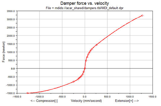
Notice the force values are positive in extension. In the actual force function, this is actually inverted so that the force acts to oppose the extension of the damper.
You can also specify gas preload force for nonlinear dampers using XML-format property files.
To specify gas preload:
1. Right-click a damper, point to its name, and then select Modify.
The Modify Damper dialog box appears.
2. Specify an XML property file.
3. Select the Curve Manager tool  .
.
. 4. Select the Properties tab.
5. Under Gas Preload, select one:
■None - No preload is added to the damper force calculations.
■Constant - A constant force is added to damper force calculations. A positive force acts to extend the damper.
■Nonlinear - Preload is calculated by interpolating a spline. The independent value of the spline is the relative displacement between the I and J markers. A positive force acts to extend the damper.
About Struts
Struts are specialized dampers designed to take bending and damping loads in the suspension. See Strut Modeling.
FMU Dampers
Any existing damper can be replaced with a Functional Mock-up Interface (FMI) submodel. This allows the user to create a "closed box" damper model. The user will first create the damper model in a controls modeling package (for example, Easy5 or Matlab/Simulink), and export this model as a Functional Mockup Unit (FMU). The FMU is assumed to be built with the following convention:
■Positive velocity means the damper is extending.
■Positive velocity produces negative force.
■If users choose to author an FMU such that positive displacement & velocity produce positive force, they will need to set the force scale factor to -1.
■Adams Car does not require any unit convention in the FMU. Users are responsible to set the scale factors if the FMU was modeled in a different unit system than the Adams Car model.
■The damper is a force object only. Any parts and constraints must be modeled in Adams.
Use of an FMU damper requires a license of Adams Controls. Any number of dampers can be replaced with FMU dampers, but there will be some Solver performance degradation associated with each FMU damper instance.
The FMU must be built for model exchange, not co-simulation.
FMU Input/Output Signal Convention
Adams sends the displacement and velocity states to the FMU and expects a force to be returned. These signals must be named according to the table below.
Type | Name | Description |
|---|---|---|
Input | Displacement | Displacement magnitude between I and J markers. |
Input | Velocity | Relative translational velocity of I marker with respect to J marker. |
Output | Force | Force acting on I part along line of sight between I and J markers. |
Note: | A positive force acts to repel the I and J parts, resisting compression. |
To create a FMU damper:
1. In Standard Interface, right-click a damper, point to its name, and then select Replace Instance.
2. Press F1 and then follow the instructions in the dialog box help for Replace Instance Definition.
3. Select OK.
To modify a FMU damper in the Standard Interface:
1. Right-click a damper, point to its name, and then select Modify. The dialog box has the damper parameters already loaded.
3. Select OK.
Working with Bumpstops
A bumpstop defines a force-displacement relationship between two parts. The bumpstop acts between user-specified coordinate reference points on each part, and conforms to the force-displacement properties described in the designated property file.
The bumpstop force is activated when the distance between the two coordinate references falls below the clearance defined for the bumpstop.
Two types of bumpstop are supported:
1. Internal: Line-of-sight, based on the SFORCE element. Use this type when the bumpstop is constrained, as in a strut.
2. External: Distance to a plane, based on the VFORCE element. Use this type when the bumpstop is not constrained radially.
The force-displacement formula is based on:
■Instantaneous distance between the user-specified coordinates defined on each part
■Impact length or clearance
■Bumpstop property file (polynomial or nonlinear stiffness with or without linear or nonlinear damping).
Learn about bumpstops:
Creating and Modifying Bumpstops
When working in Template Builder, you can create bumpstops and then modify them. When working in Standard Interface, you can only modify bumpstops. Learn about the interface modes.
To create a bumpstop:
1. From the Build menu, point to Forces, point to Bumpstop, and then select New.
3. Select OK.
To modify a bumpstop in the Template Builder:
1. To display the modify dialog box, do one of the following:
■From the Build menu, point to Forces, point to Bumpstop, and then select Modify. To load the parameters for a specific bumpstop, you must specify the bumpstop you want to modify.
■Right-click a bumpstop, point to its name, and then select Modify. The dialog box has the bumpstop parameters already loaded.
3. Select OK.
To modify a bumpstop in the Standard Interface:
1. In Standard Interface, right-click a bumpstop, point to its name, and then select Modify. The dialog box has the bumpstop parameters already loaded.
3. Select OK.
Calculation of Force Characteristics
The force in a bumpstop is the sum of an elastic force, a damping force, and a metal-to-metal force. The TeimOrbit property file supports only the elastic force. The XML (XML File Format) bumpstop property file supports various options for the three force components. For the Internal bumpstop method, the options available for calculating elastic force (Felastic) are:
■polynomial - The formulation of the force is based on a third-order polynomial whose equation can be expressed as follows:
Felastic = POLY(MAX(0, impact_length – DM (marker i, marker j)), 0,0, LinearRate, QuadraticRate, CubicRate)
■nonlinear (spline based) - The formulation of the force is based on the Akima spline interpolation of a nonlinear characteristic:
Felastic = AKISPL(MAX(0, impact_length - DM(marker i, marker j)), 0,Spline)
The XML property file specifies the impact length (named "bumper height" in the XML editor). Therefore, if you select an XML property file, the Impact Length option in Car is disabled and the value from the property file is used instead.
The elastic force becomes active only when the instantaneous distance between the markers on the two parts is less than the impact length. The impact length term depends on the distance type. If you select Clearance, the impact length becomes:
dmCalc - Clearance
where:
■Clearance - Value you specify
■dmCalc - Initial displacement computed between the I and J markers
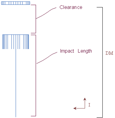
The following figure shows the clearance and impact length.
In an XML bumpstop property file, you can also enable a damping characteristic. If you enable the damping characteristic, the force is dependent on the deflection and velocity of the I and J markers.
Damping (viscous) forces can be:
■linear - If you include in the property file a linear damping value other than zero, then the total force exerted between the I and J parts is equal to the maximum of zero or sum of the elastic force specified above and the damping force. The damping force is as below:
Fdamping = STEP (MAX(0, impact_length - DM(i,j)), 0, 0, 0.1, -
dampingRate * VR (marker i, marker j))
■nonlinear (spline based) - If you include in the property file a nonlinear damping value, then the total force exerted between the I and J parts is equal to the maximum of zero or sum of the elastic force specified above and the damping force. The damping force is as below:
Fdamping = STEP (MAX(0, impact_length - DM(i,j)), 0, 0, 0.1, -
AKISPL (VR (marker i, marker j), 0, dampingSpline ))
If you select the External bumpstop type, the above equations use the DZ() and VZ() functions in place of the DM() and VR() functions respectively. The penetration is calculated as:
penetration = MAX(0, impact_length - DZ(marker i, marker j, reference marker))
■polynomial - The formulation of the force is based on a third-order polynomial whose equation can be expressed as follows:
Felastic = POLY(penetration, 0, 0, LinearRate, QuadraticRate, CubicRate)
■nonlinear (spline based) - The formulation of the force is based on the Akima spline interpolation of a nonlinear characteristic:
Felastic = AKISPL(penetration, 0, Spline)
If you select the External bumpstop type and use an XML property file, the bumper height specified in the XML property file can be used to specify a metal-to-metal force. The metal-to-metal force is activated when the distance between I and J markers is smaller than the bumper height:
Fmetal = STEP(penetration - bumperHeight, 0, 0, 1mm, metalToMetalRate) * (penetration - bumperHeight)
Note: | The metal-to-metal rate can only be set in an XML property file. |
About Bumpstop Property Files
The bumpstop component supports the following types of property files:
■TeimOrbit (TeimOrbit File Format) bumpstop property files (extension .bum). Standard TeimOrbit bumpstop property files correspond to nonlinear elastic forces with linear damping equal to 0 formulation. Learn more with Bumpstop dialog box help.
■XML (XML File Format) bumpstop property file. The XML bumpstop property file enables data sharing with other MSC Software applications, and allows greater flexibility and a wider range of bumpstop formulation choices. In particular, the XML bumpstop property file supports various methods and options for the calculation of force characteristics, as explained in Calculation of Force Characteristics. You work with XML files in the Property File Editor.
Hammerstein Bumpstops
To replace a Bumpstops with Hammerstein Bumpstop in the Standard Interface:
To modify a Hammerstein Bumpstop in the Standard Interface:
1. In Standard Interface, right-click a Hammerstein Bumpstop, point to its name, and then select Modify. The dialog box has the Hammerstein model's parameters already loaded.
2. Press F1 and then follow the instructions in the dialog box help for Modify Hammerstein Bumpstop.
3. Select OK.
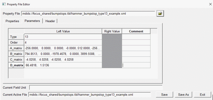
Hammerstein Property File Editor:
The parameter tab of the Property File Editor can be used to specify hammerstain model's inputs parameters like Order and A, B, C, D matrixes.
Working with Reboundstops
A reboundstop defines a force-displacement relationship between two parts. The reboundstop acts between user-specified coordinate reference points on each part, and conforms to the force-displacement curve described in a designated property file. The reboundstop force is activated when the displacement between the two coordinate references exceeds the defined clearance.
The force-displacement formula is based on:
■Instantaneous distance between the user-specified coordinates defined on each part
■Impact length or clearance
■Reboundstop property file (polynomial or nonlinear stiffness with or without linear or nonlinear damping.)
Learn about reboundstops:
Creating and Modifying Reboundstops
When working in Template Builder, you can create reboundstops and then modify them. When working in Standard Interface, you can only modify reboundstops. Learn about the interface modes.
To create a reboundstop:
1. From the Build menu, point to Forces, point to Reboundstop, and then select New.
3. Select OK.
To modify a reboundstop in the Template Builder:
1. To display the modify dialog box, do one of the following:
■From the Build menu, point to Forces, point to Reboundstop, and then select Modify. To load the parameters for a specific reboundstop, you must specify the reboundstop you want to modify.
■Right-click a reboundstop, point to its name, and then select Modify. The dialog box has the reboundstop parameters already loaded.
3. Select OK.
To modify a reboundstop in the Standard Interface:
1. In Standard Interface, right-click a reboundstop, point to its name, and then select Modify. The dialog box has the reboundstop parameters already loaded.
3. Select OK.
Force Calculation
The force in a rebound stop always acts to keep two parts from moving farther apart. The force is active only when the distance between the parts as computed by dm(i,j) exceeds the impact length. You specify the impact length directly or indirectly as the initial clearance in the rebound stop. When you specify a clearance, the impact length is calculated from the clearance as follows:
dmCalc + Clearance
where:
■Clearance is the value you specify
■dmCalc is the initial displacement computed between the i and j markers
Further, the force in a rebound stop is the sum of an elastic force, a damping force, and a metal-to-metal force. The TeimOrbit property file supports only the elastic force. The XML property file supports various options for the three force components. The options available for calculating elastic force (F elastic) are:
■polynomial - The for calculated using a third-order polynomial. The Adams Solver function expression is:
Felastic = POLY(MAX(0,DM(i, j) - impact_length),0,0,- linearRate,-quadraticRate,-cubicRate)
■nonlinear (spline based) - The force is interpolated using Akima's method based on force vs. deflection data.
Felastic = -1.0*(AKISPL(MAX(0,DM( i , j ) - impact_length),0,Spline))
The following figure shows the clearance and impact length.
The damping force always acts in opposition to the velocity. In an XML (XML File Format) reboundstop property file, the options for calculating damping force are:
■linear - You specify the dampingRate, and the damping force is the product of dampingRate, velocity, and a STEP function. The STEP function depends on the displacement in the rebound stop and ensures the damping force is continuous with displacement.
Fdamping = STEP (MAX(0, DM(I,J) - impact_length), 0, 0, 0.1, -dampingRate
* VR (marker i, marker j))
■nonlinear (spline based) - The damping force is interpolated using Akima’s method from a table of force vs. velocity. Again, a STEP function dependent on the displacement in the rebound stop ensure that the damping force is continuous with displacement.
Fdamping = STEP (MAX(0, DM(I,J) - impact_length), 0, 0, 0.1, -AKISPL
VR (marker i, marker j), 0, dampingSpline))
The bumper height specified in the XML property file can be used to specify a metal-to-metal force. The metal-to-metal force is activated when the distance between I and J markers exceeds the impact length + bumper height:
Fmetal = STEP(penetration - bumperHeight, 0, 0, 1mm, -metalToMetalRate * (penetration - bumperHeight))
The metal-to-metal rate can only be set in an XML property file.
About Reboundstop Property Files
The reboundstop component supports the following types of property files:
■TeimOrbit (TeimOrbit File Format) reboundstop property files (extension .reb) - Standard TeimOrbit reboundstop property files correspond to nonlinear elastic forces with linear damping equal to 0 formulation. Learn more with Reboundstop dialog box help.
■XML (XML File Format) reboundstop property file - The XML reboundstop property file enables data sharing with other MSC Software applications, and allows greater flexibility and a wider range of reboundstop formulation choices. In particular, the XML reboundstop property file supports various methods and options for the calculation of force characteristics, as explained in Calculation of Force Characteristics. You work with XML files in the Property File Editor.
Working with Aerodynamics
Aerodynamics defines the aerodynamic forces and moments which act on a vehicle. Aerodynamics modeling provides the sensitivities of a particular vehicle to wind gusts, drag, lift and side forces. This program requires wind tunnel aerodynamic coefficient data for the vehicle being modeled and they must be taken according to SAE J1594 conventions for Vehicle Aerodynamics Terminology.
The aerodynamics acts at user-specified coordinate reference points on the part, and conforms to the wind angle-coefficients curve described in a designated property file. The aerodynamics force is always active if defined unless you create a group to toggle its activity.
The two methods are provided for modeling aerodynamics. The different types are represented by different property file classes. Aerodynamic property files are stored in the aero_forces.tbl subdirectory of a vehicle database. The following property file types are supported:
■AeroDynamicForcesOnePointForceProperties
■AeroDynamicForcesTwoPointForceProperties
■AeroDynamicForcesOnePointForceProperties3d
■AeroDynamicForcesTwoPointForceProperties3d
The default location for the one-point aerodynamics property is:
■X=Midpoint between front and rear wheel centers
■Y=Midpoint between left and right wheel centers (front)
■Z=Vertical height of the front contact patch
Figure 4 One-Point Aerodynamic Force
The default location for the two-point aerodynamics property is:
■X= X Location of wheel centers (front and rear)
■Y=Midpoint between left and right wheel centers (front and rear)
■Z=Vertical height of the contact patch (front and rear)
Figure 5 Two-Point Aerodynamic Force
The user is provided an option of using two wind force points of application or only one. (In the property file, this is referred to as "OnePoint" or "TwoPoint"). This option depends on the source and type of wind tunnel data.
Wind velocity and angle defined in the Cross Wind Analysis by wind property file (.wnd in Adams Car), allow the modeler to simulate wind fans, chaotic wind forces and so on. The wind properties can be dependent on distance (useful for wind fan modeling) or on time (which allows to user to more easily investigate vehicle sensitivity versus speed). The wind velocity and angle are with respect to ground. The routine calculates relative wind speed and direction based on vehicle velocity and yaw angle.
The aerodynamics coefficients can be in 2D spline form or 3D spline form. For a 2D spline, the independent variable is the wind angle. If a 3D spline is used, the coefficients are determined by spline lookup of wind angle and vehicle pitch angle. The 2D and 3D coefficients are stored is separate property files. Therefore, to switch from one method to other, users will have to specify appropriate property file.
The force application MARKER must be in vehicle SAE orientation. The origin of this MARKER must coincide with the location at which the coefficients were measured (or be placed at the location to which the coefficients were resolved). Learn more about aerodynamics modeling.
Learn about aerodynamics:
■Creating and Modifying Aerodynamics
■Calculation of Aerodynamic Force
■About Aerodynamics Property Files
Creating and Modifying Aerodynamics
When working in Template Builder, you can create aerodynamics and then modify them. When working in Standard Interface, you can only modify aerodynamics. Learn about the interface modes.
To create an aerodynamics:
1. From the Build menu, point to Forces, point to Aerodynamics, and then select New.
2. Press F1 and then follow the instructions in the dialog box help for Create/Modify Aerodynamics
3. Select OK.
To modify an aerodynamics in the Template Builder:
1. To display the modify dialog box, do one of the following:
From the Build menu, point to Forces, point to Aerodynamics, and then select Modify. To load the parameters for a specific aerodynamics, you must specify the aerodynamics you want to modify.
2. Right-click a aerodynamics, point to its name, and then select Modify. The dialog box has the aerodynamics parameters already loaded.
3. Press F1 and then follow the instructions in the dialog box help for Create/Modify Aerodynamics.
4. Select OK.
To modify an aerodynamics in the Standard Interface:
1. In Standard Interface, right-click a n aerodynamics, point to its name, and then select Modify. The dialog box has the aerodynamics parameters already loaded.
2. Press F1 and then follow the instructions in the dialog box help for Modify Aerodynamics.
3. Select OK.
Force Calculation
The aerodynamics force always acts on the part. Learn about implementation of aerodynamics modeling.
About Aerodynamics Property Files
The aerodynamics component supports the following types of property files:
XML (XML File Format) aerodynamics property file - The XML aerodynamics property file enables data sharing with other MSC Software applications, and allows greater flexibility and a wider range of aerodynamics formulation choices. In particular, the new XML aerodynamics property file supports various methods and options for the calculation of aerodynamics force, as explained in aerodynamics modeling. You work with XML files in the Property File Editor.
Working with Contact Definitions
A contact definition defines a force-displacement relationship between two parts. The contact definition acts between user-specified geometries or flexible bodies, and conforms to the force-displacement properties described in the associated Contact Parameter Array.
The contact force is activated when the distance between the contact pair reaches zero.
The force-displacement formula is based on:
■Instantaneous distance between the user-specified contact pair
■Contact parameters stored in an associated array.
Creating and Modifying Contact Definitions
When working in Template Builder, you can create contact definitions and then modify them. When working in Standard Interface, you can only activate/deactivate contact definitions. You can also modify contact parameters in Standard Interface. Learn about the Interface Modes.
To create a contact definition:
1. From the Build menu, point to Contact Definitions, and then select New.
2. Press F1 and then follow the instructions in the dialog box help for Create/Modify Contact Definition.
3. Select OK.
To modify a contact definition in the Template Builder:
To display the modify dialog box, do one of the following:
1. From the Build menu, point to Contact Definitions, and then select Modify. To load the parameters for a specific contact definition, you must specify the contact definition you want to modify.
2. From the Model Browser, right-click a contact definition, and then select Modify. The dialog box has the contact definition parameters already loaded.
3. Press F1 and then follow the instructions in the dialog box help for Create/Modify Contact Definition.
4. Select OK.
To modify contact parameters in the Standard Interface:
1. In Standard Interface, from the Model Browser, right-click a contact parameter array, point to its name, and then select Modify. The dialog box has the contact parameters already loaded.
3. Select OK.
To activate/deactivate a contact definition in the Standard Interface:
1. From the Adjust menu, point to Contacts, and then select Definition Table.
3. Select OK.
Force Calculation
See section CONTACT in the Solver Statements guide.
Working with Runtime Clearances
A runtime clearance defines a distance measurement between user-specified geometries or flexible bodies.
Creating and Modifying Runtime Clearances
When working in Template Builder, you can create runtime clearances and then modify them. When working in Standard Interface, you can only activate/deactivate runtime clearances. Learn about the Interface Modes.
To create a runtime clearance:
1. From the Build menu, point to Runtime Clearances, and then select New.
2. Press F1 and then follow the instructions in the dialog box help for Create/Modify Runtime Clearance.
3. Select OK.
To modify a runtime clearance in the Template Builder:
To display the modify dialog box, do one of the following:
1. From the Build menu, point to Runtime Clearances, and then select Modify. To load the parameters for a specific runtime clearance, you must specify the runtime clearance you want to modify.
2. From the Model Browser, right-click a runtime clearance, and then select Modify. The dialog box has the runtime clearance parameters already loaded.
3. Press F1 and then follow the instructions in the dialog box help for Create/Modify Runtime Clearance.
4. Select OK.
To activate/deactivate a runtime clearance in the Standard Interface:
1. From the Adjust menu, select Runtime Clearance.
3. Select OK.