Flexible Body Modeling with Adams Solver
The topics in this section explain how to use Adams Flex with Adams Solver:
It would also be helpful to read the information in the other sections of the Adams Flex online help even if you are using Adams Solver with Adams Flex. They contain overview material that pertain to Adams Solver as well as Adams View.
Steps in Modeling Flexible Bodies with Adams Solver
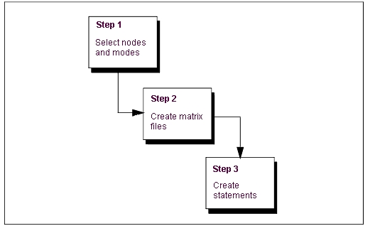
To model a flexible body in Adams Solver, you do the following as shown in the figure below.
Step 1: Select Modes and Nodes | Select the modes that you want included in the dynamic simulation and decide which nodes will have markers attached. |
Step 2: Create a Matrix File | Translate an MNF or MD DB created from a finite element analysis (FEA) program to a matrix file. As you do the translation , you specify the selected modes and nodes. You also specify the units for the matrix file. You use the units that you are using in your dataset (.adm file), not in your MNF. |
Step 3: Create Statements | Create the following statements in your dataset: ■FLEX_BODY statements that describe a flexible body and associate it with matrix elements. ■MARKER statements that create markers at any node locations where you want to attach modeling elements, measure deformations, and more. You must have included these nodes in the matrix file. ■MATRIX statements that correspond to the matrices in the matrix file. |
Steps in Using Adams Solver and Adams Flex
Selecting Modes and Nodes
To increase the efficiency of Simulations, you should only include those modes that are necessary for the motion that you are attempting to model. You should, however, use caution when not including modes. If you do not include a mode, the flexible body cannot take on the particular shape of that mode and may be incorrect.
Adams Solver needs modal information corresponding to any node that has a marker on it. This information is stored in the matrix file. If you do not include a node, you cannot directly place a marker on the flexible body at that location. There is no computational overhead for nodes in a matrix file that do not have associated markers nor for markers that are not used. You should, therefore, also select nodes that may be of interest in the future.
Selecting modes without the visual assistance that Adams View provides can be difficult. You can use the Adams Flex Toolkit to browse a Modal Neutral File (MNF) to determine the modes and nodes that you want included in the matrix file. Learn about Browsing an MNF or an MD DB. Adams View also lets you automatically disable modes based on their strain energy contribution.
Creating Matrix Files
Adams Solver uses a matrix file to describe the properties of a flexible body. The matrix file contains inertia invariants and the portion of the flexible body modes shapes that correspond to marker locations. The basic FLEX_BODY formulations call for 14 matrices but the number can vary depending on:
■If all invariants except 5 and 9 exist in the MNF or MD DB, and mesh coarsening has been performed, the matrices INVAR5 and INVAR9 cannot be created and may not appear in the matrix file.
■If the flexible body has a preload, the file will contain an additional PRELOAD matrix.
■If the flexible body has modal loads defined, the file will contain an additional MODLOAD matrix.
■If the flexible body has a generalized damping matrix specified, the file contains an additional GENDAMP matrix.
■If the flexible body has an edge data specified, the file contains additional EDGE_xx list, where xx denotes an arbitrary edge ID.
As you can see, there can be as few as 12 or as many as 17 matrices, currently.
The 14 standard matrices list the selected modes and nodes, invariants, and pertinent segments of the mode shapes. The 14 matrices are:
■GENSTIFF
■INVAR1
■INVAR2
■INVAR3
■INVAR4
■INVAR5
■INVAR6
■INVAR7
■INVAR8
■INVAR9
■T_MODE
■R_MODE
■SELNOD
■SELMOD
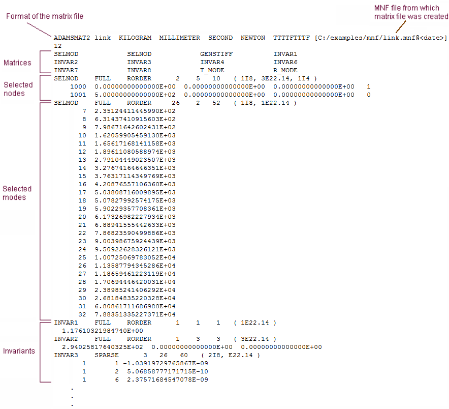
The following shows the first part of a matrix file. The end of the matrix file that is not shown contains matrix data.
From this example, you can see that 12 matrices are defined in this matrix file and their names are listed. The first matrix defined is SELNOD. It is a full matrix with dimensions of 2 rows and 5 columns for a total of 10 elements. Each row represents a node that is referenced by a marker with a connection to the model. Listed is its node number, coordinates and whether it was promoted as an attachment node ("1") or not ("0") during MNF generation. From this example, node 1000 was promoted as an attachment and 1001 was not. The fifth column is when a simplified representation of the flex body is requested, and it may be missing in older version of Adams.
The next matrix defined in this example is SELMOD. It is a full 2 by 26 by 2 matrix for a total of 52 elements. It provides the mode number and its frequency of each mode selected for the simulation.
You generate a matrix file by translating an MNF file. You use the translator available through the Adams Flex Toolkit. The matrix file is in ADAMSMAT or ADAMSMAT2 format, and you should only create it using the translator.
For information on creating an MNF, see Translating FE Model Data. For information on creating MD DB, see Create an MD DB using MSC Nastran. For information on using the Adams Flex toolkit, see Translating an MNF or an MD DB into a Matrix File.
Matrix File
Writing Flexible Body Statements
You need to create several statements in your dataset: FLEX_BODY, MARKER, and MATRIX, as explained in the next sections below. Example dataset contains an example of a dataset containing the necessary statements. You can copy the text of the dataset to a text editor so you can use it as a start to your dataset.
Example Dataset Containing Flexible Body Statements
FLEX_BODY/1
, MATRICES = 1, 2, 3, 4, 5, 6, 7, 8, 9, 10, 11, 12, 13, 14
, INVARIANTS = T:T:T:T:T:T:T:T:F
, CRATIO = USER(.01,100,.1,500,1)
!
MARKER/39
, FLEX_BODY = 1
, NODE_ID = 21
!
MARKER/40
, FLEX_BODY = 1
, NODE_ID = 1
, QP = 1, 0, 0
!
MARKER/41
, FLEX_BODY = 1
, NODE_ID = 211
, QP = 1, 0.5, 0
!
MARKER/42
, FLEX_BODY = 1
, NODE_ID = 231
, QP = 0, 0.5, 0
!
MARKER/43
, FLEX_BODY = 1
, NODE_ID = 116
, QP = 0.5, 0.25, 0
!
!---------------------------- DATA STRUCTURES ----------------------
!
MATRIX/1, FILE = myfile.mtx, NAME = GENSTIFF
MATRIX/2, FILE = myfile.mtx, NAME = INVAR1
MATRIX/3, FILE = myfile.mtx, NAME = INVAR2
MATRIX/4, FILE = myfile.mtx, NAME = INVAR3
MATRIX/5, FILE = myfile.mtx, NAME = INVAR4
MATRIX/6, FILE = myfile.mtx, NAME = INVAR5
MATRIX/7, FILE = myfile.mtx, NAME = INVAR6
MATRIX/8, FILE = myfile.mtx, NAME = INVAR7
MATRIX/9, FILE = myfile.mtx, NAME = INVAR8
MATRIX/10, FILE = myfile.mtx, NAME = INVAR9
MATRIX/11, FILE = myfile.mtx, NAME = T_MODE
MATRIX/12, FILE = myfile.mtx, NAME = R_MODE
MATRIX/13, FILE = myfile.mtx, NAME = SELNOD
MATRIX/14, FILE = myfile.mtx, NAME = SELMOD
!
UNITS/
, FORCE = NEWTON
, MASS = KILOGRAM
, LENGTH = METER
, TIME = SECOND
!
END
Creating the FLEX_BODY Statement
The FLEX_BODY statement includes information on a flexible body and its associated matrix file.You must have a FLEX_BODY statement in your dataset. The FLEX_BODY statement also must include a MATRICES argument, damping ratio, and invariants. The MATRICES argument identifies the MATRIX statements in your dataset. For flexible bodies, you always have 14 MATRIX statements, and, therefore, 14 parameters to the MATRICES argument.
Notes: | Including a very high frequency mode in a flexible body analysis poses a challenge to the Adams integrators. This is because the excitation of this mode, at any frequency, can lead to numerical excitation of the mode at its high resonance frequency. While the Adams integrators are capable of tracking this response, this is rarely the analyst's intention and simulation times become unacceptable. You can control this behavior by carefully applying modal damping on a mode-by-mode basis. The CRATIO argument on the FLEX_BODY statement accepts an expression (rather than a SCALAR as in 8.2) and should be used in one of the following ways: ■Default damping is used when you omit the CRATIO argument. The default damping is 1% of critical damping for all modes with a natural frequency below 100, 10% for modes under 1000, and 100% for all modes over 1000. ■To give the same damping ratio to all modes, set CRATIO to a scalar value between 0 and 1. Recall that CRATIO is a ratio of critical damping. To turn off default damping, set CRATIO=0 for zero damping (this was the 8.2 default). Note that since CRATIO is now an expression, it must be followed by a backslash (\) except when it is the last keyword on the statement. ■To vary the damping based on individual modes or run-time results, you can set CRATIO equal to an Adams Solver function expression. In particular, you can use the function expressions FXFREQ and FXMODE to apply different damping levels to different modes. ■To control the modal damping of individual modes using a user-written subroutine, use CRATIO=USER(...). Adams Solver obtains the damping ratios for the selected modes through a call to the DMPSUB subroutine. |
Creating MARKER Statements
You use the MARKER statement to create a marker at every node location where you want to create an attachment. The node IDs that you use in the MARKER statement to define a location must match those in the SELNOD section of the matrix file.
■For information on the matrix file, see Creating Matrix Files.
■For information on placing markers at locations where no nodes exist, see the Adding Markers to Flexible Bodies.
Creating the MATRIX Statement
You need a MATRIX statement for each of the 14 matrixes in the matrix file. The format of the MATRIX statement for a flexible body is:
MATRIX/n FILE = myfile.mtx, NAME = string
The arguments are:
■n, which maps to a number in the MATRICES argument in the FLEX_BODY statement.
■FILE=, which is the name of the matrix file.
■NAME=, which specifies the name of a matrix in the file that FILE identifies (for example, GENSTIFF).