Multi-Gear Shaft
The Multi-Gear Shaft feature enables you to model complex gear trains in high level of fidelity for various NVH studies in Adams View and Adams Car environment. It enables you to create a shaft flexible body consisting of one or more cylindrical gear and one or more involute spline elements along with gear tooth flexibility for accurate gear contact simulations. The Multi-Gear Shaft feature removes some of the previous limitations of Full Flex Gear modeling for cylindrical gears.
This section provides a brief overview of the modeling steps in Adams environment which are specific to this modeling approach. It also describes in more detail all the preprocessing steps to get required model files ready for building Adams model with a flexible shaft and wheel body consisting of multiple cylindrical gears and involute spline elements with use of Full Flex Gear and Full Flex Spline modeling approach, respectively. In current release there is no support for bevel / hypoid, cylindrical worm, and lead-screw gears.
Note: | The model files generated within this process are not compatible with those produced for cylindrical gears via Gear AT Mesh dialog box with the Full Flex Gear mode. Hence you cannot combine two cylindrical gear elements in a gear force coming from the two distinct preprocessing methods. |
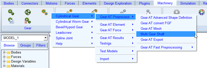
Figure 78 Access to Multi Gear Shaft preprocessing
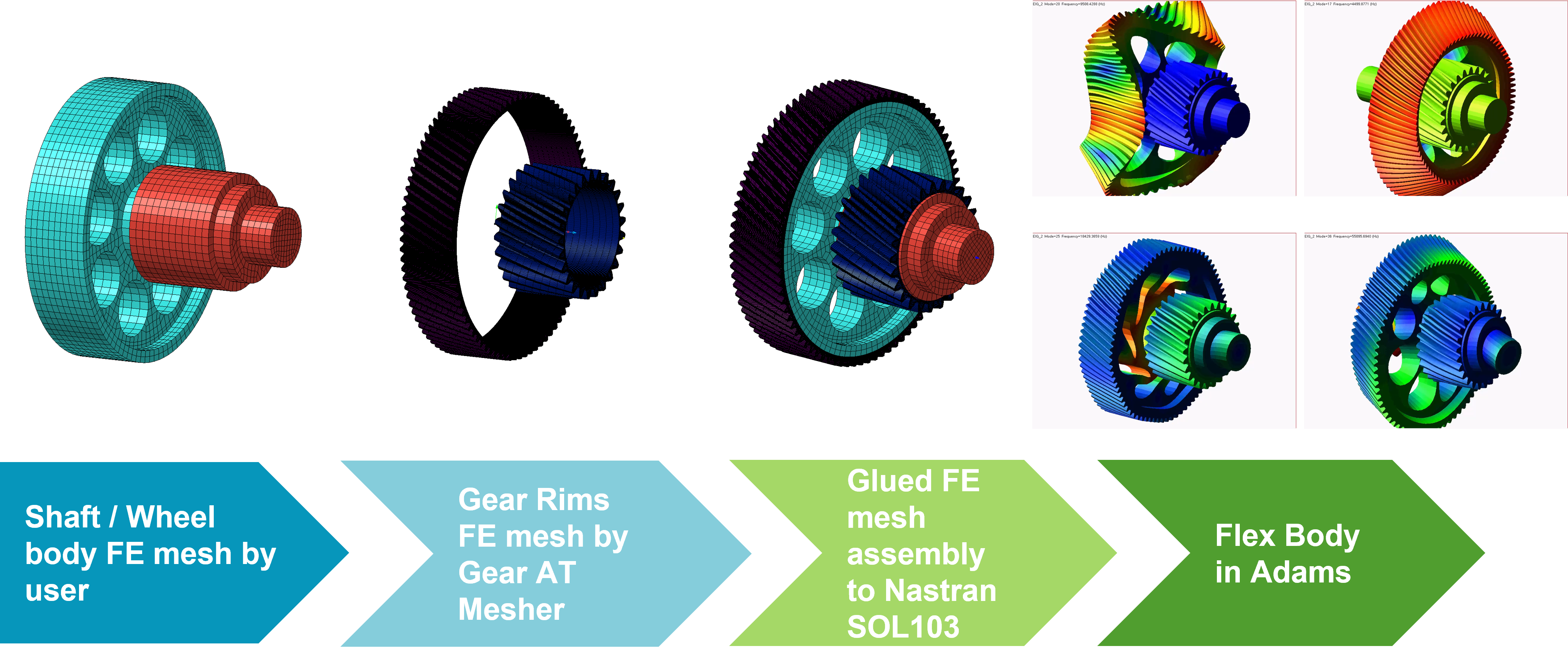
Figure 79 Overview of Multi-Gear Shaft process
Preprocessing starts by opening Multi-Gear Shaft FE Preprocessing dialog box and browsing for shaft / wheel body FE mesh (*.BDF file) prepared by user - see Figure 79 and Figure 80
The Gear AT Mesher writes additional gear rim bulk data files per cylindrical gear and involute spline element and one Nastran input deck for SOL103. The input deck references all bulk data files by INCLUDE statement and it includes all pertinent glue contact cards to define connections of dissimilar FE meshes of the shaft / wheel body and gear rims. To make glue contact connection, you need to ensure the common surfaces of a glue contact pair is within tolerance of 0.05 mm by consistent value of a gear Rim Diameter – see Figure 83.
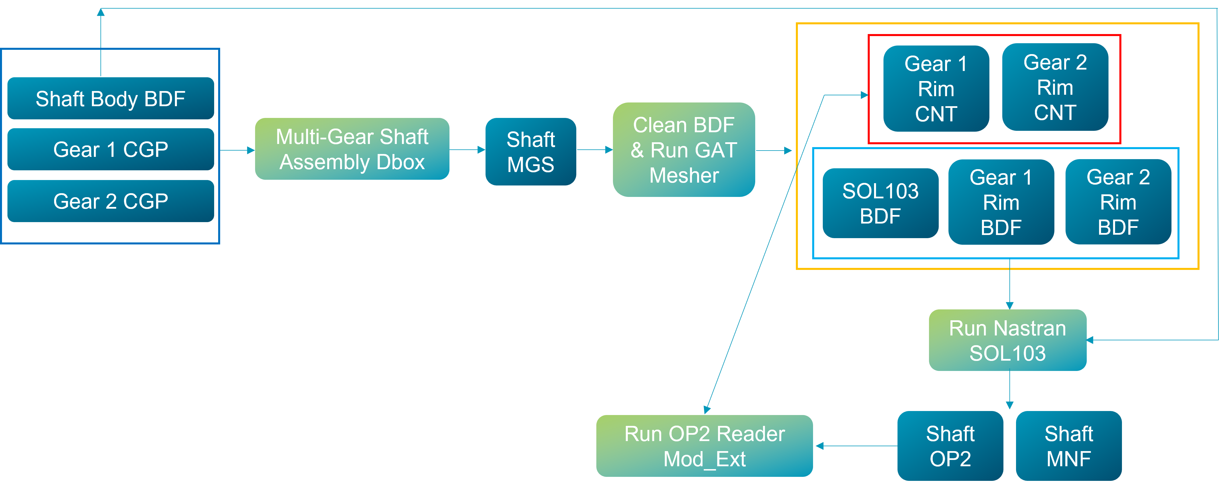
Figure 80 Data flow of Multi-Gear Shaft process
After the preprocessing is complete, an MNF file will be used to create a new flexible body in Adams model. You need to make it part of your model by positioning / orienting and attaching it to other bodies as appropriate or replace existing rigid body with the new flexible body.
The flexible body's local body reference frame (LBRF) corresponds to the origin of the FE structure which is transformed by Gear AT Mesher to coincide with attachment node of the first gear element and the Z axis is aligned with the shaft rotational axis.
When connecting the flexible shaft to your model be advised to parametrize I and J markers of all joints and bushings so it does not get broken during subsequent orientation of the flex body during a gear force creation.
Create cylindrical gear and involute spline elements by selecting interface markers of the shaft flexible body. It is assumed that you have preprocessed each gear for the use with so called Flexible Tooth modeling approach hence there are stiffness files (*.CGS and *.ISS) available for gear force creation.
The last step is to create all relevant cylindrical gear forces and involute spline forces between gear elements attached to adjoining shafts. Be aware that one of the flexible shaft bodies is automatically oriented relative to the other to set up proper gear meshing. In case of complex gear trains the sequence of gear force creations hence orientation has to be considered appropriately. However, the orientation of a shaft can be reset afterwards and new orientation can be set up without need to recreate a gear force – read section New Gear AT Force for more information.
The tab options of Multi-Gear Shaft dialog box are following:
■Main
■Gear
Main
For the options | Do the following |
|---|---|
Property file | The property file stores all FE related parameters of a multi-gear shaft (*.MGS) assembly including file paths to gear property files and path to shaft bulk data file. It serves as an input file to Gear AT Mesher to write Nastran input deck for SOL103. In Create mode: ■enter name of new *.MGS file In Edit mode: ■right click to browse for existing *.MGS file ■all relevant fields in various tabs of the dialog box will be filled up by content of multi-gear-shaft property file |
File navigator icon | One can use the File navigator icon to select destination directory for new *.MGS file. In Adams Car, there is an option menu to select destination database, the *.MGS file will be stored in gear_at.tbl directory. |
Shaft Input Deck | Browse for *.BDF file of a shaft / wheel body FE structure. A gear rim will be glued together, thus creating a single flexible body in Adams model. |
Preprocessor | Choose one of following options: In Create mode: ■Full Preprocessing ■Write MGS file only ■Mesher Only In Edit mode: ■Full Preprocessing ■Write MGS file only ■Mesher Only ■Nastran SOL103 only ■Mode Shape Extract only Full Preprocessing: Performs all preprocessing steps mentioned below in a sequence to get all model files ready for building model with a flexible shaft consisting of multiple cylindrical gears and involute spline elements. Write MGS file only: Use this option to write multi-gear shaft property file without running any preprocessing steps. Mesher Only: Use this option to verify that FE Mesh is valid before running SOL103 or when you need to edit Nastran input deck before Nastran job execution or in case you prefer to run Nastran job on a different computer. Nastran SOL103 only: Use this option after you have manually edited Nastran input deck from Mesher Only preprocessing. The SOL103 is performed by running either standalone Nastran installation if available, or the Adams embedded Nastran Solver known as ViewFlex. In case of standalone Nastran installation is used, it makes use of Nastran SMP feature with all number of processors on the compute if corresponding license is available Mode Shape Extract Only: Use this option when you have run Nastran SOL103 only or when you performed Nastran SOL103 job outside of Gear AT. Before execution, make sure you provide Nastran OP2 result file from SOL103 in the directory where a multi-gear shaft Property File (*.MGS) is located |
Extended definition
You need to provide FE model of a shaft and wheel body which are usually connected by permanent glued contact in Nastran SOL103. Most of times contact bodies are defined by BSURF (MSC Apex) which is defined by IDs of elements. Gear rims are not modelled by user but by Gear AT Mesher.
Gear AT Mesher creates all glued contact related cards to:
■Define glue contact between shaft / wheel body and gear rims by BCBODY1 with BCPROP which is defined by PSOLID ID, which has advantage of taking all common surface boundaries.
■Define contact table (BCTABL1) taking all existing user defined glue contact into account.
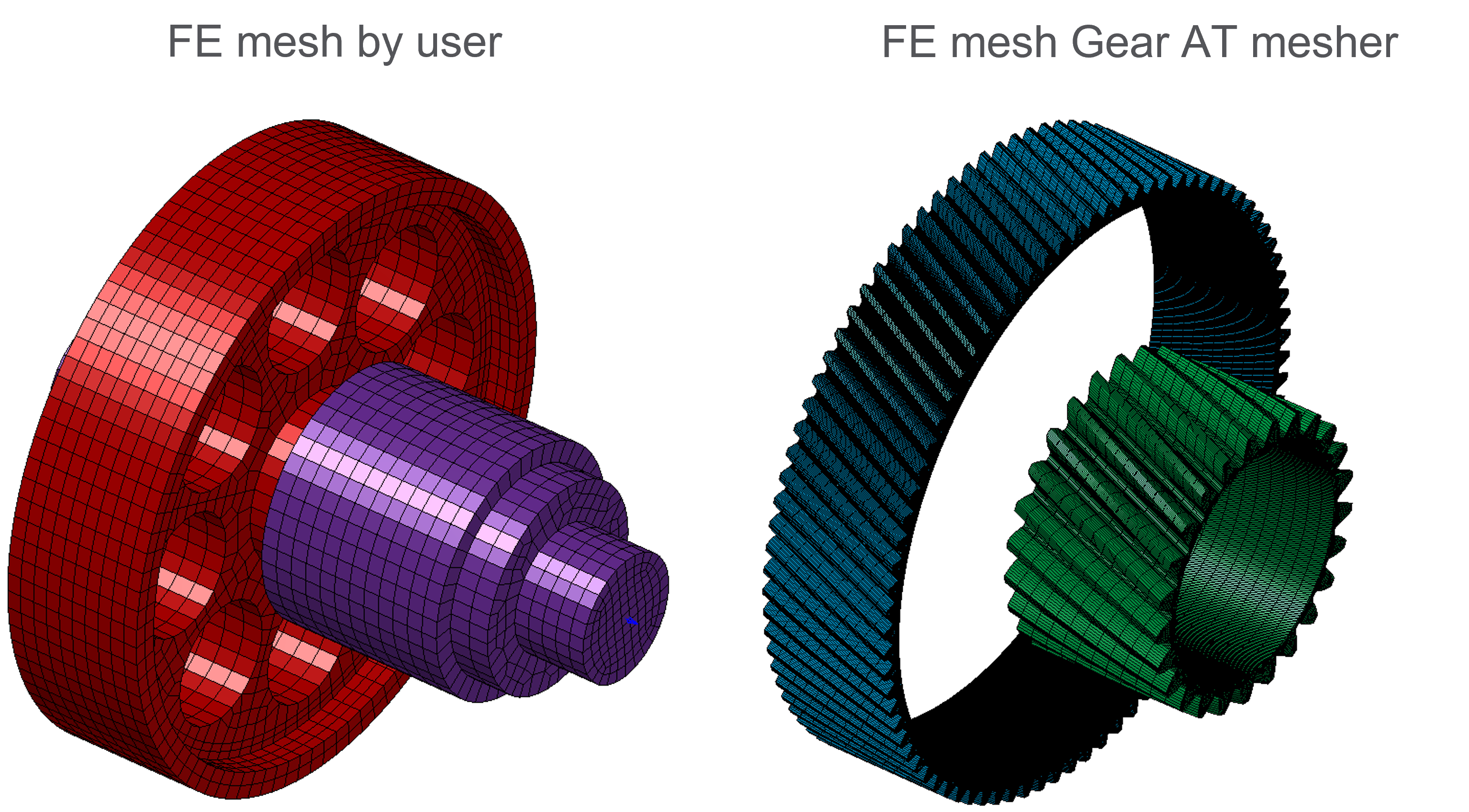
Figure 81 Multi-Gear Shaft FE Meshes
It is good practice to always verify flex body after importing to Adams View. Especially check the flexible body mass and make sure that the first 6 frequencies are very close to 0.0 Hz (rigid body modes) and ensure that all these rigid body modes are disabled. In case there are 12 rigid body modes, the glue contact failed most probably due to higher distance between wheel body and toothed rim FE structures than the ERROR specified in a *_SOL103.bdf file. If the value of tolerance is not appropriate you can manually edit the input deck before running SOL103; search for ERROR keyword in BCONPRG Nastran card. Additionally there are some useful Nastran statements written in case control section of a *_SOL103.bdf file, which you might find helpful in troubleshooting some issues with glued contact such as plotting contact status or debugging glued contact grounding issues. Those statements are commented out but you can uncomment it before running Nastran SOL103 only preprocessor. Please read Nastran documentation to learn more about those Nastran statements.
Shaft Input Deck
Gear AT Mesher writes Nastran input deck for SOL103, which references all bulk data files by INCLUDE statement. Therefore the shaft input deck provided by user must not contain executive control section, case control section and following Nastran cards and delimiters:
■CEND - delimiter at the end of executive control section
■BEGIN BULK - delimiter at the end of case control section
■EIGRL
■PARAM, AUTOMSET, YES
■PARAM, AUTOQSET, YES
■ASET / ASET1
■DTI
■ENDDATA - last entry in all the input files
Most of the non-required Nastran cards are automatically commented out right after browsing the Shaft Input Deck file so you do not have to edit the file manually. The original Shaft Input Deck file provided by the user is preserved with the BDF% extension. However in case the Gear AT Mesher preprocessing or Nastran SOL103 is failing you need to check if the Shaft Input Deck file is properly cleaned up.
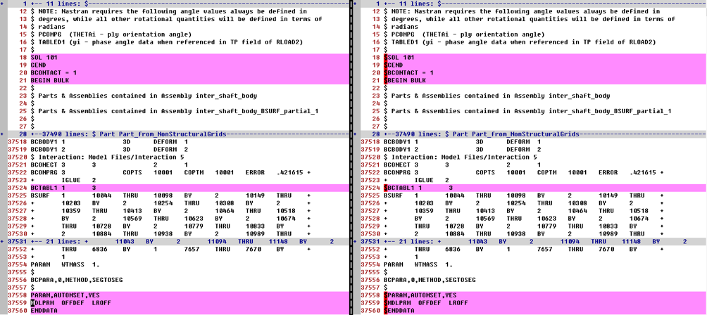
Figure 82 Original vs. cleaned up Shaft Input Deck BDF file
Currently there are following prerequisites for the user FE model of the shaft / wheel body:
■Shaft / wheel body outer diameter has to match the Rim diameter of the gear defined in the Shape Definition step - see Figure 83
■Gear element attachment node has to be located in the middle of gear width - see Figure 84
■all data must be defined in following consistent set of units: MGG, N, MM, S (WTMASS = 1.0)
■if there are other glue contacts defined in the Shaft Input Deck file, the FE elements on the common surface with gear rims, i.e. those which are supposed to be glued with the gear rim FE meshes should not be part of existing user defined contact bodies. In such a case the user defined contact body should be defined by depicting corresponding contact face rather than complete shaft / wheel body solid – see Figure 85
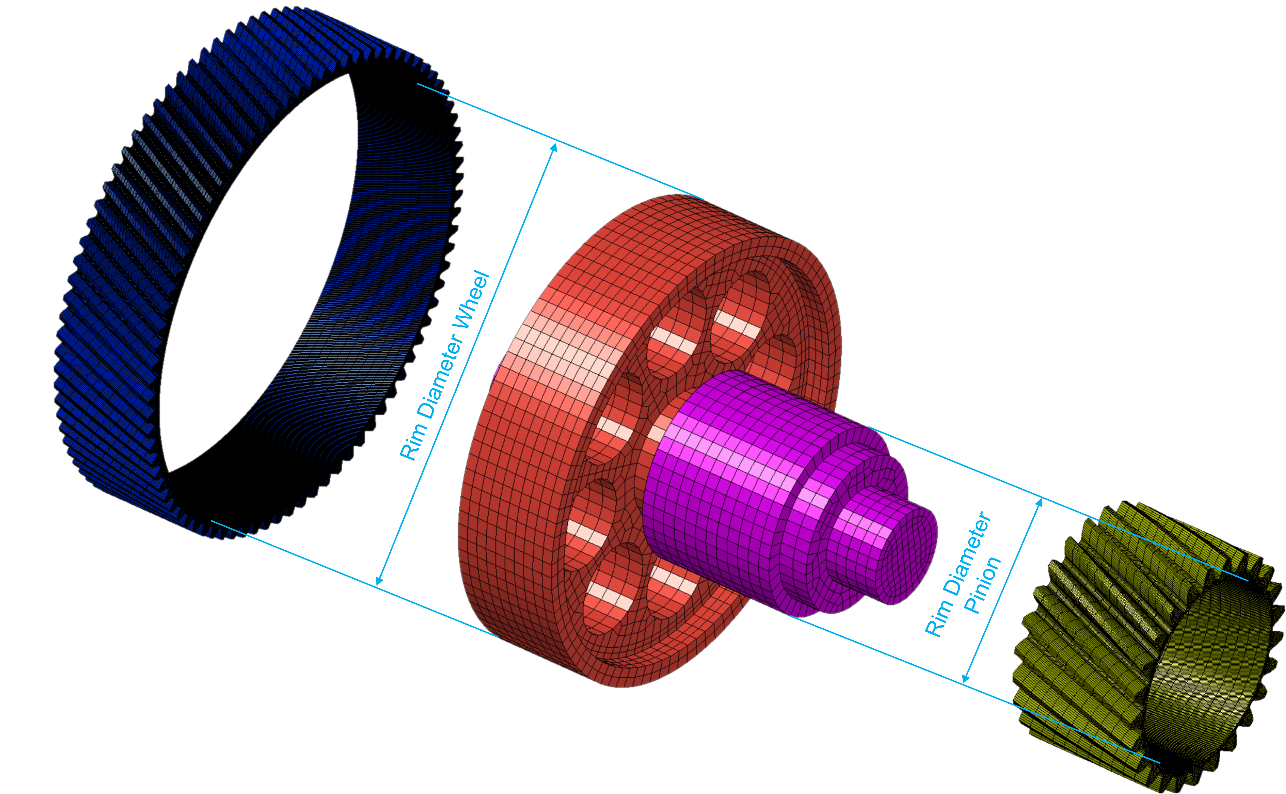
Figure 83 Rim diameter - modeling
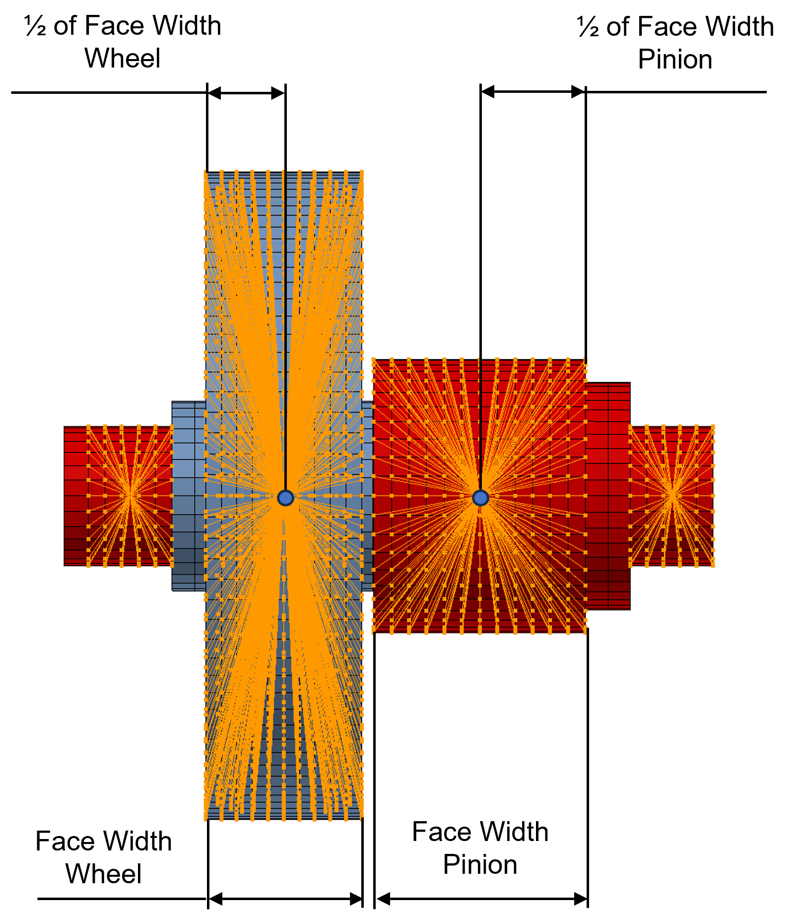
Figure 84 Attachment node location - modeling prerequisite
The Shaft Input Deck file could consist of several FE meshes glued together. Gear AT Mesher will accept those already defined and will create additional glue contact per gear rim by BCBODY1 with BCPROP card. The BCPROP internally creates BSURF with all elements of FE mesh with defined PSOLID ID. In case any user defined contact body contains the same elements, Nastran SOL103 will write following warning into *_SOL103.f06 file, which can be safely disregarded:
*** USER WARNING MESSAGE 22809 (mcnt_surf_geom2.cpp)
Some elements are shared by multiple BCBODY1, BCSURF or BCGRID entries, this may lead to unexpected results.
The element id, up to 3 BID's for each element are listed below.
EID BID1 BID2 BID3
1 BCBODY1 2 BCBODY1 3
2 BCBODY1 2 BCBODY1 3
…
unless following fatal message is present:
*** USER FATAL MESSAGE 8146
which means that the contact body defined by Gear AT Mesher contains no FE elements since all have been assigned to user defined contact body. To resolve that conflict, you have to redefine the contact body by selecting just those elements corresponding to assumed contact face rather than complete shaft / wheel body solid, hence the BSURF of user defined contact body will not contain of all elements – see bottom part of Figure 85

Figure 85 User contact body - modeling prerequisite
General
The parameters of the general tab give you the possibility to control modal content of the shaft flexible body. It also helps to align shaft rotational axis so the Gear AT Mesher pre-requisite is fulfilled.
Note: | Whenever possible, you should always correlate eigen frequencies of your FE model to the modal test data. It is advised to verify flexible body before incorporating it to your Adams model, for more information refer Verifying Flexible Bodies. |
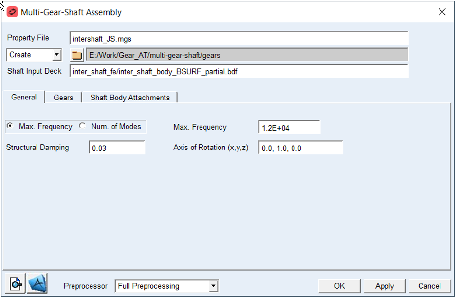
Figure 86 Multi-Gear Shaft dialog box - General tab
For the options | Do the following |
|---|---|
If Max. Frequency radio button is selected: | |
Max. Frequency | Enter value of Max. Frequency to define cut off frequency for fixed boundary normal modes extraction during SOL103 solution process (Nastran EIGRL card). Default option: 1.2E+04 |
If Number of Modes radio button is selected: | |
Number of Modes | Enter value of Number of Modes for fixed boundary normal modes extraction during SOL103 solution process (Nastran EIGRL card). Default: 10 |
Structural Damping | Enter value of Structural Damping to define Generalizes Damping of flexible shaft. Default: 3.0E-02 |
Axis of Rotation | Enter vector in 3D to define axis of the shaft rotation in FE basic coordinate system. It is used by Gear AT Mesher to define CORD2R card (coordinate system) so the FE structure is transformed to have the shaft flexible body rotational axis aligned with Z axis in Adams. Default: 0.0, 1.0, 0.0 |
Extended definition:
Maximum Frequency: The value defines upper limit for frequency range of interest for fixed boundary normal modes extraction during SOL103 solution process. It corresponds to V2 parameter of EIGRL card – for more information read Nastran documentation.
Number of modes: Enter appropriate number of fixed boundary normal modes (also known as component dynamic modes) to define sufficiently large modal basis of your shaft / wheel body. It corresponds to ND parameter of EIGRL card – for more information read the Nastran documentation. Note that the default value of 10 will be most probably insufficient to capture real deformations of the flexible wheel body structure.
Structural Damping: The value defines structural damping in the form of percentage of modal deformation for given mode. This damping is in contrast to modal damping proportional to deformation. The damping matrix is generated and stored in MNF file of the shaft / wheel body assembly.
Axis of Rotation: The shaft / wheel body FE model gets transformed by Gear AT Mesher:
■New FE basic system is located at RBE node of the gear Node ID in the 1st row of Gears table.
■Z axis of the FE basic system is directed along Axis of Rotation vector defined in the General tab.
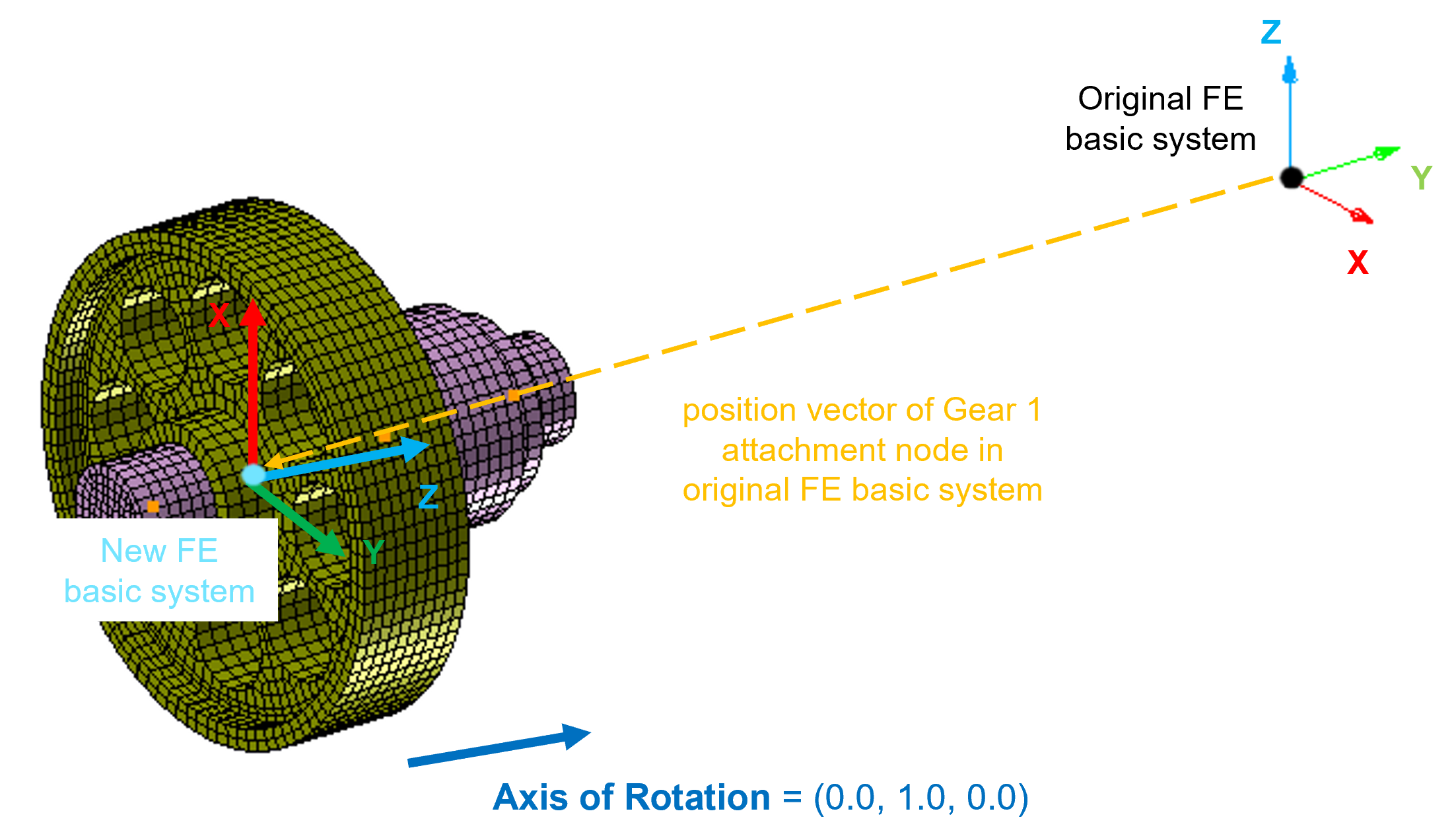
Figure 87 New FE basic system and shaft rotational axis
Gear
Fill up the table to define topology of the shaft / wheel body and related gears as well as FE mesh division of the gear rims.
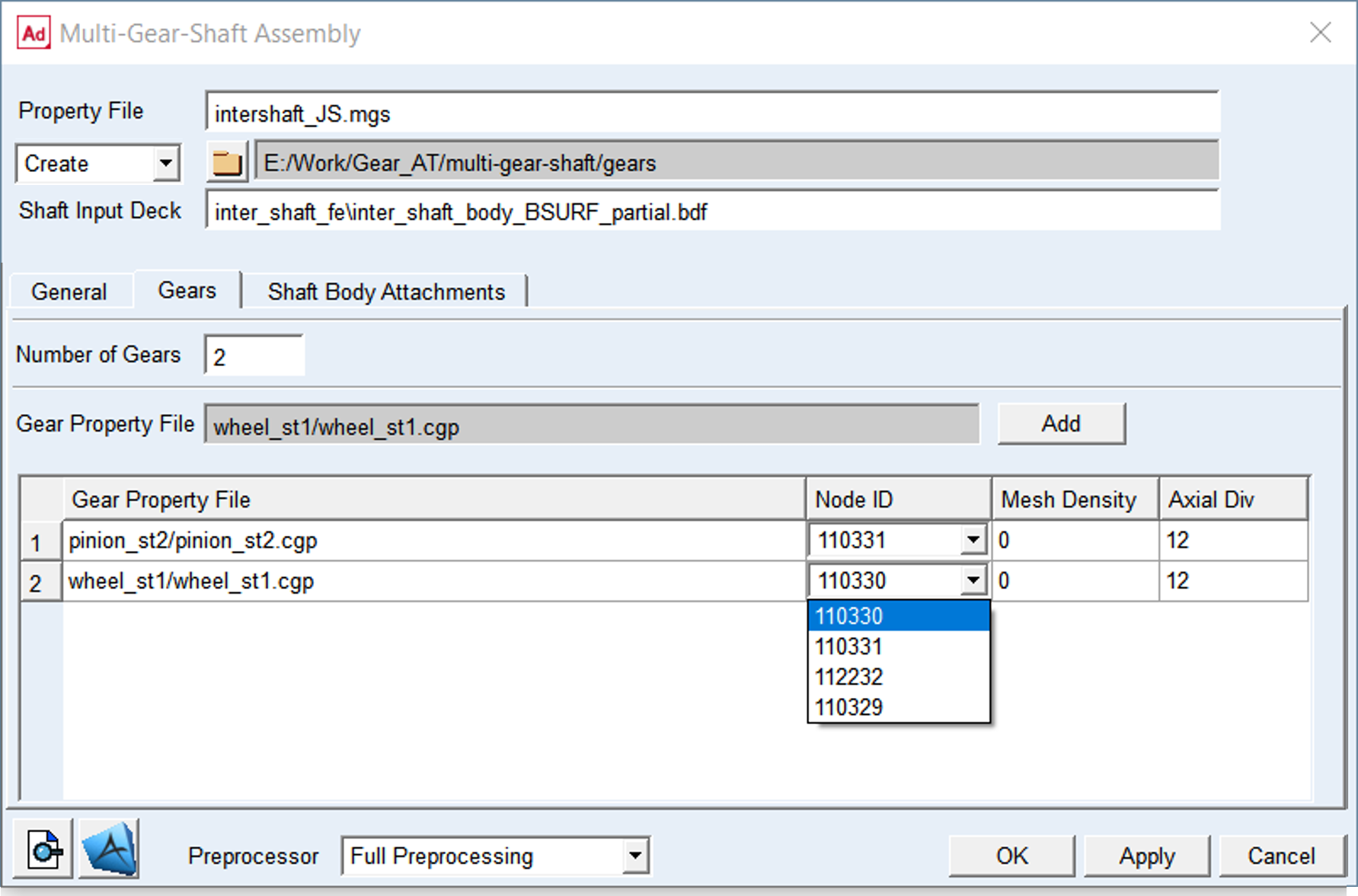
Figure 88 Multi-Gear Shaft dialog box – Gears tab
For the options | Do the following |
|---|---|
Number of Gears | Enter the number of gears per shaft before filling up the table. Default: 2 |
Gear Property File (gray field) | This file contains all essential gear geometrical parameters, such as number of teeth, normal module, etc. and the gear rim diameter required for gear rim FE mesh generation by Gear AT Mesher. To populate the Gears table, in gray field do a right mouse click to browse for Gear Property File (*.CGP / *.ISP file), then do left mouse click in a table cell and click the Add push button to fill up the cell. |
Dialog box table: Each row of the table defines location of a gear element based on coordinate of a node ID, and FE mesh division of the gear rim. | |
Gear Property File (dialog box cell) | Fill up the column of the table by browsing in the Gear Property File field, selecting appropriate cell and the Add button. |
Node ID | To position Gear Rim FE mesh relative to shaft body structure, select appropriate Node ID from the option menu If selected Create mode option: ■Select Node ID from an option menu which is auto populated by all RBE2 / RBE3 nodes from Shaft Input Deck ■From the choices of Node IDs, one need to choose the ID that relates to the gear in the corresponding row of the table If selected Edit mode option: ■After browsing the *.MGS file, the Node ID option per gear is filled up with the ID corresponding to the respective gear |
Mesh Density | Enter value from 0 to 5 representing 8, 16, 24, 32, 40, 48 elements along the involute. Default: 0 |
Axial Divisions | Enter number of FE elements along the lead direction of a gear (Z-axis). The number should be a multiple of 3. Default: 12 |
Extended definition:
Node ID: It defines the ID of attachment node (Nastran GRID card ID) per gear element to which appropriate toothed rim FE mesh will be located in assembled FE model. The option menu is populated by every node of RBE2 and RBE3 element found in the Shaft Input Deck BDF file.
The FE structure is transformed by Gear AT Mesher to coincide with attachment node of the first gear element in the table and the Z axis is aligned with the shaft rotational axis.
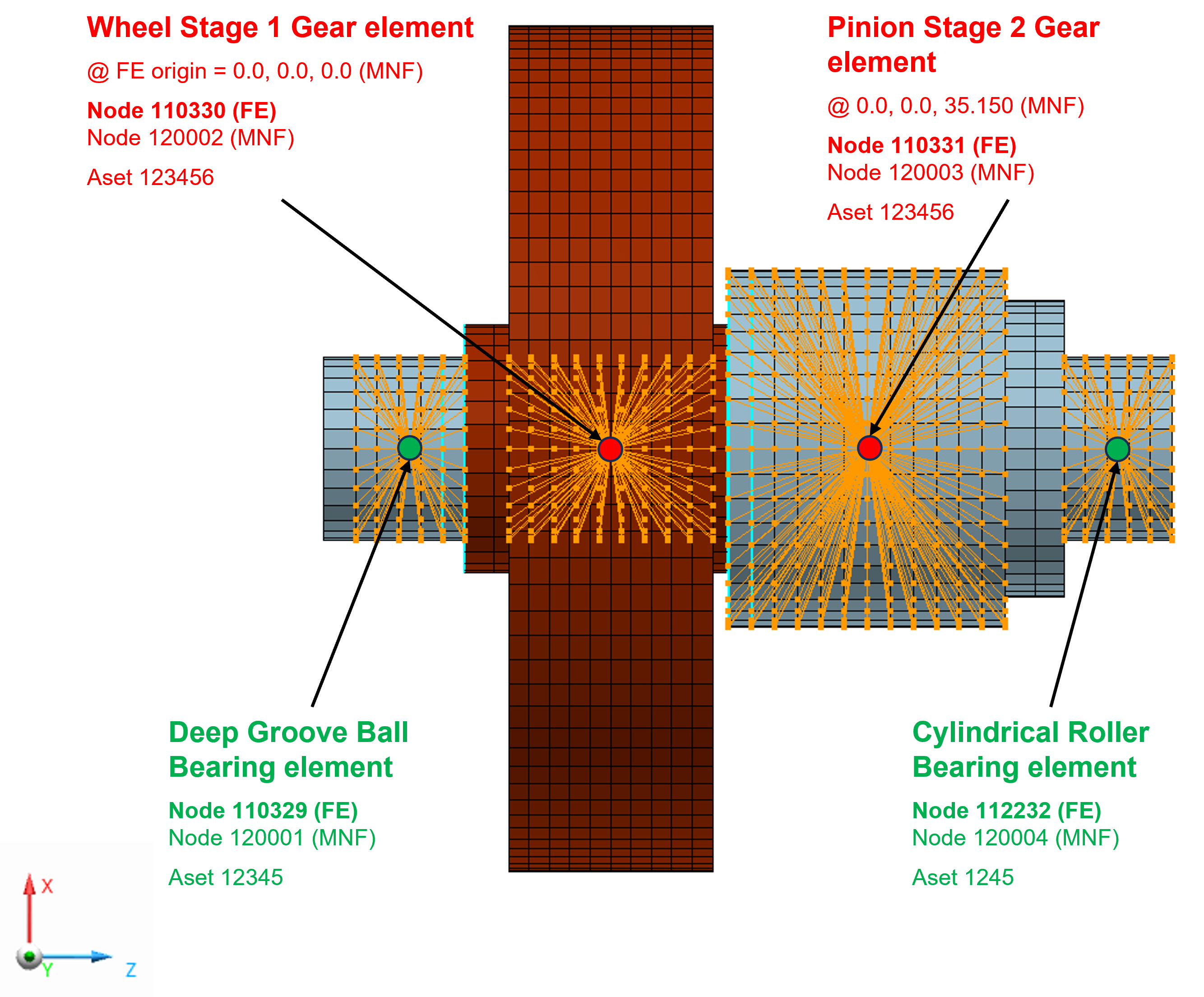
Figure 89 Gear and Attachment Node IDs
Mesh Density: It defines the number of finite elements along the involute curve of tooth profile – see Figure 90. Valid input entries for mesh density are 0 to 5, representing 8, 16, 24, 32, 40 or 48 elements along the contact line. For the Full Flex modeling, the value of 0 provides sufficient FE mesh resolution to capture flexibility of the gear rim.
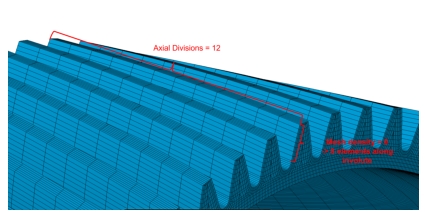
Figure 90 Full Flex Gear rim mesh divisions
Axial Divisions: It defines division of the tooth width into a number of equidistant sections in lead direction of a tooth flank.
It is suggested to use a number which is a multiple of 3. A default value is 12 axial divisions.
Shaft Body Attachments
To make flexible shaft body a part of your model, you need to connect it to elements in your model by use of kinematic or flexible connections and apply forces to it. To learn more about the rules, best practices, and limitations, refer Connecting Flexible Bodies to Your Model.
To capture the effects of attachments on the flexible body the modal basis also needs to include so called constraint modes (boundary DOF). This is achieved by usage of RBE2 and RBE3 elements and promoting its reference node to be so called attachment or interface node by ASET1 Nastran card. You also need to define attachment degrees of freedom in Nastran SOL103 analysis set which are defined in the new FE basic system, where X-axis and Y-axis are normal to the shaft axis of rotation and Z-axis coincides with rotational axis – see Figure 87.
The table in Shaft Body Attachment tab is automatically populated by all reference grids of RBE2, RBE3 and ASET cards found in the Shaft Input Deck you provided however it could be expanded and edited appropriately.
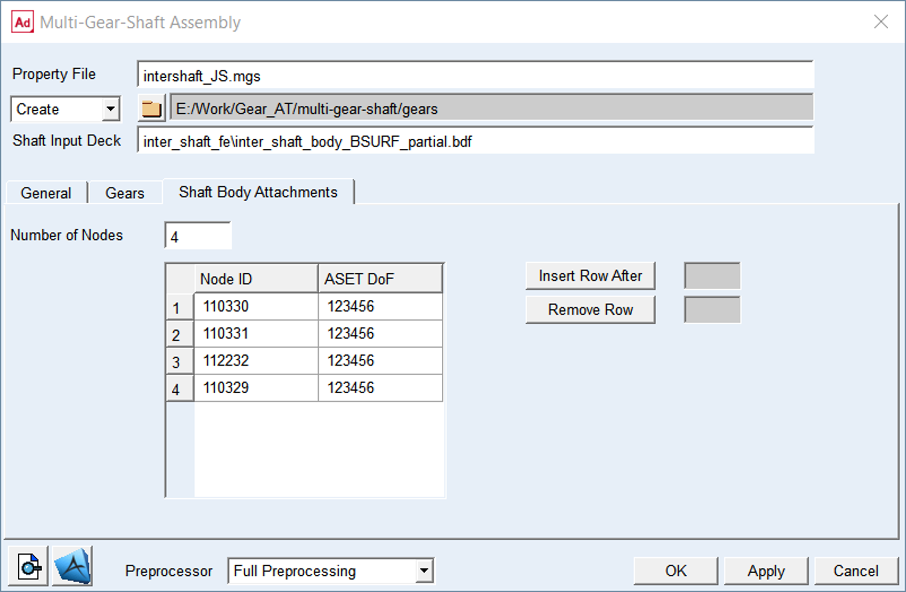
Figure 91 Multi-Gear Shaft dialog box – Shaft Body Attachment tab
For the options | Do the following |
|---|---|
Number of Nodes | Enter the number of required attachment nodes of all gears of the shaft including all shaft supports (bearings) and coupling connections. This field is auto populated by the content of the Shaft Input Deck you provided however it could be edited appropriately. Default is 5 |
Node ID | Enter the Node ID of the flexible shaft / wheel body attachments – see Figure 89. This column of the table is auto populated by the content of the Shaft Input Deck you provided however it could be edited appropriately. |
ASET DoF | Define degrees of freedom (DOF) per attachment node to be used in the modal analysis which refer to the new FE basic system – see Figure 87. 1 = X-axis translation 2 = Y-axis translation 3 = Z-axis translation 4 = X-axis rotation 5 = Y-axis rotation 6 = Z-axis rotation For example, if you want to apply fixed joint to attachment node enter 123456. To apply spherical joint enter 123. Default is 123456 Note: Make sure you hit the Enter key after you define the value in table. Otherwise your value will not be applied! |
Insert Row After | In case the value of Number of Nodes is small, one can increase the number. Enter the number of the row after which you want the new row to be added into the table, the value of Number of Nodes field will be updated automatically. Afterwards, enter the required Node ID value in the newly created cell and also enter the value of DoF. |
Remove Row | In case that the value of Number of Nodes is large, you can decrease the number. Enter the number of the row which you want to remove from the table, the value of Number of Nodes field will be updated automatically. |
 | The button displays the content of the *.MGS property file. |
 | The button allows you to browse for Nastran bulk data file and opens the FE model in MSC Apex. |
Extended definition:
Number of Nodes: Before executing Nastran SOL103 you need to define attachment nodes of all gears of the shaft including all shaft supports (bearings) and coupling connections (also known as interface node) which will be written in the MNF file and can be used to connect the flexible body to other parts and elements of your Adams model. When you create a Full Flex Gear element in your Adams model, you select reference marker on the flexible shaft / wheel body to attach the gear element to. Gear AT creates for you an appropriate constraint to attach gear element to the part which takes all 6 DoF. To capture the effects of applied load on the flexible body, the modal basis also needs to include so called constraint modes accompanied to that reference marker. Therefore the reference marker should be connected to so called attachment (interface) node.
Node ID: Enter the node id of each flexible shaft / wheel body attachment. This node could belong either to RBE2 or RBE3 element. In order to avoid the use of “PARAM, AUTOMSET, YES” which is required for defining ASET with attachment nodes belonging to RBE3 element, there is CBUSH element created per attachment node along with coincident node which becomes so called interface node in Adams.
Therefore, you will find a different ID of the interface node in Adams than specified in this table cell.
ASET DoF: Enter the degree of freedom (DoF) per attachment node of your flexible shaft / wheel body FE model. When you build a flexible body into an Adams model, you interface with the body using a variety of attachments, either joints or forces. In Adams Flex, you can model the variable boundary conditions at attachment points, which are nodes that have been idealized for attachment, by preserving all six Cartesian degrees of freedom (DoFs) of those points as you export the flexible body from your finite element analysis (FEA) program. An attachment point is equivalent to a super-element exterior grid point. Each attachment point normally contributes six modal DOF. Corresponding to each attachment point DOF is one constraint mode, which is a static mode shape due to a unit displacement of that DOF while holding all other DOFs of all attachment points fixed. A large number of attachment points can result in unwieldy data files and can significantly impact CPU time, if the associated modes are enabled during an Adams dynamic simulation. It is advised to limit the number of constraint modes by prescribing adequate DoFs per attachment node. For instance, if you intend to model spherical joint, it is enough to preserve translational DoF for the ASET (123). However, the ASET for attachment of the gear element to a shaft should always preserve all DoFs (123456).