Gear AT Mesh
Once the gear data are defined in the *.CGP property file you are ready to preprocess gear tooth FE model to get tooth flank contact surfaces and stiffness matrix for Gear AT contact simulation. The Figure 58 shows how to access Gear AT Mesher interface to preprocess your gear before you could define Gear AT Element in Adams model. The data flow involved in the mesh is depicted on Figure 59.
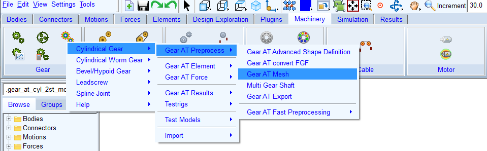
Figure 58 Launch of Gear AT Mesh
FE preprocessing starts by launching Gear AT mesher (orange color; see Figure 59) with input data from *.CGP file prepared in the Gear AT Advanced Shape Definition step and *.opt file which consists of data you input in the FE Data tab of the mesher dialog box. Output of the mesher is Adams geometry *.shl file, flank contact surface for rigid contact modeling in *.CGS file and updated *.CGP file by inertia data of the gear. In order to include gear tooth flexibility in contact simulation, Nastran SOL 101 needs to be executed (green color). The Gear AT op2_reader extends the content of *.CGS file with results from Nastran run. To take into account flexibility of the wheel body (blue color), Nastran SOL 103 is executed which produces MNF and OP2 result file. The MNF file is referenced in the gear property CGP file which is used to create the Full Flex Gear element. In addition, there is CNT file created by the mesher, which is updated by modal results of SOL103. The CNT file is also referenced in the gear property CGP file. Whenever the MNF file is recreated, the CNT file has to be updated with the result of OP2 file by the Mode Shape extraction preprocessor.
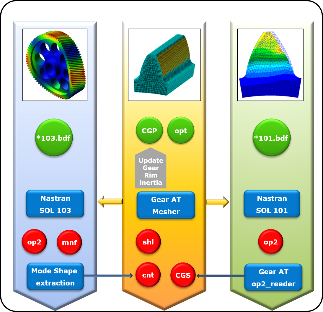
Figure 59 Data flow of Gear AT Mesh
The tab options of Create Gear AT Mesh dialog box are
Main
For the options | Do the following |
|---|---|
Property file | Browse for existing gear property file to preprocess FE mesh model |
Mode | Select one from available gear modeling options: ■Rigid Gear ■Flex Tooth ■Full Flex Gear |
Import *.opt | The parameters for the meshing are stored in a file with the extension *.opt. if this file exist, you can retrieve this data through the Import *.opt button. |
Preprocessor | Choose one from following options: ■Internal ViewFlex: use this option when there is no Nastran installation available and you don’t wont to draw additional Adams View license to execute the ViewFlex. Please note that additional ViewFlex license is required ■External ViewFlex: use this option when there is no Nastran installation available. On background there is SOL103 running by Adams embedded Nastran Solver. This option allows you to continue working since ViewFlex is executed in external shell window hence the main window remains active. Please note that additional Adams View and ViewFlex license is required. This option is not available on linux ■Internal Nastran: use this option when you have Nastran installation available. It makes use of Nastran SMP license if available ■External Nastran: use this option when you have Nastran installation available. It makes use of Nastran SMP license if available. This option allows you to continue working since standalone Nastran is executed in external shell window hence the main window remains active. Please note that additional Nastran license is required. This option is not available on linux ■Mesher Only: use this option to verify that FE Mesh is valid before running SOL101 and SOL103 or you need to run Nastran on different computer ■Mode Extraction Only (Full Flex Gear mode): use this option when you have run Nastran outside of Gear AT. Before execution make sure you provide Nastran OP2 result file from SOL103 in the directory where gear Property File is located ■OP2 Reader Only (Flex Tooth mode): use this option when you have run Nastran outside of Gear AT. Before execution make sure you provide Nastran OP2 result file from SOL101 in the directory where gear Property File is located |
General
The general tab (Figure 60) displays some parameters of the gear wheel, which are stored in the *.cgp file. However, none of them are editable as the tooth profile was defined in the Gear AT Advanced Shape Definition step already.
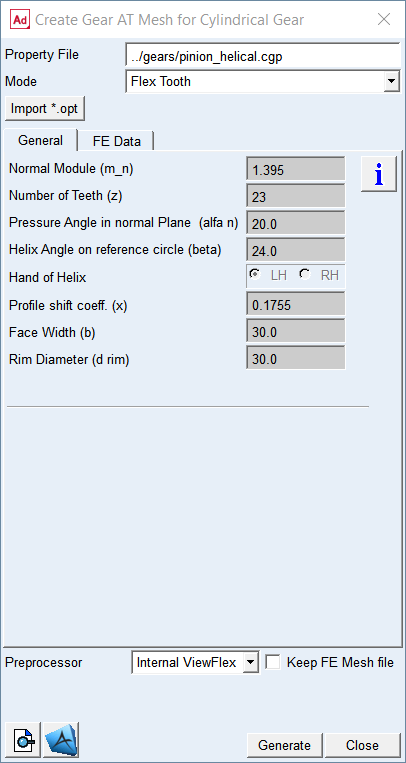
Figure 60 Gear AT mesh dialog box - General tab
FE Data
You can control resolution of FE mesh and contact mesh of flexible tooth as well as resolution of Adams shell graphics thus performance of the model.
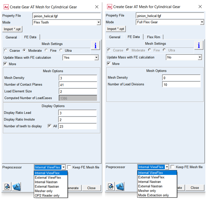
Figure 61 Gear AT mesh dialog box - FE data tab of Flex Tooth and Full Flex Gear
For the options | Do the following |
|---|---|
Mesh Settings | ■Coarse - Mesh Density = 2 ■Moderate - Mesh Density = 3 ■Fine - Mesh Density = 4 ■Ultra - Mesh Density = 5 Default option: Moderate |
Update Mass with FE calculation | Choose one of the options Yes or No. In case you select Yes the Gear AT Element mass properties will computed by the Gear AT Mesher and updated in the cgp file. NOTE: For Rigid Gear and Flex Tooth the mass properties correspond to the gear ring only. Wheel body is supposed to be modeled by the user. In case of Full Flex Gear the mass properties of flexible body are comprised in MNF file, hence the data from the MASS datablock of cgp file are not used. Default: No |
If selected More option: | |
Mesh density | For Flex Tooth option: Enter value from 2 to5 representing 24, 32, 40 or 48 elements along the involute; see Figure 63 Default: 3 For Full Flex Gear option: Enter value from 0 to 5 representing 8, 16, 24, 32, 40, 48 elements along the involute. Default: 0 |
If selected Full Flex Gear option: | |
Number of Lead Divisions | Enter a number of FE elements along lead direction of a gear (Z-axis) |
If selected Flex Tooth option: | |
Number of Contact Planes | It defines division of the tooth width into a number of equidistant sections in lead direction. Following default values are implemented: num. of cont. planes = 20 * (1 - u) + 30 * u where: u = width / (2 * module * 10) |
Load Element Size | Define the number of finite elements per section in lead direction. Enter value from 1 to 5 (2 means there are 2 elements between the contact planes); see Figure 63 |
Computed Number of LoadCases | This value indicates number of static load cases to be applied on tooth contact flank to define Flex Tooth stiffness matrix. It is computed based on the mesh settings defined above to inform user about size of FE model. |
Display Ratio Lead | Enter a value between 1 and 3 to define resolution of a gear shell graphics along lead direction. 1 means fine, 2 means normal and 3 means coarse resolution; see Figure 64. A coarse resolution with gears of high helix angle can result in tessellated display of tooth geometry. |
Display Ratio Involute | Enter the value between 1 and 3 to define resolution of a gear shell graphics along involute direction. 1 means fine, 2 means normal and 3 means coarse resolution for the shell graphics); see Figure 64 |
Number of Teeth to display | Enter a number of teeth to be created for a gear shell geometry. For full gear toggle All teeth of a gear. In case of segment gear enter required number of teeth. |
The parameters for the meshing are stored in a file with the extension *.opt. If this file exists, you can retrieve this data through the Import *.opt toggle.
Extended definition:
Update mass with FE calculation
Make your choice about Update mass with FE calculation option. In case you select Yes the Gear AT Element mass properties will correspond to the gear ring only, what is effectively the mass of solid represented by the shell graphics. It is assumed you will define the mass properties of the gear wheel body by the shaft part to which you attach the Gear AT Element. In case you defined mass by User Input in Mass tab of the Gear AT Advanced Shape Definition dialog box you should opt for No to not Update mass with FE calculation, hence the Gear AT Element you will define later on will represent mass properties of the gear ring and gear wheel body. In case of Full Flex Gear the mass properties of flexible body are comprised in MNF file, hence the data from the MASS data block of CGP file are not used.
Mesh settings
Choose from Coarse, Moderate, Fine, and Ultra options, which are predefined options to control FE mesh and load mesh division over the tooth flank. You can switch on the toggle More to manually enter all input parameters.
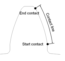
Figure 62 Definition contact line
Mesh Density
It defines the number of finite elements along the contact line (involute curve of tooth profile); see Figure 62 and Figure 63. The contact line represents portion of the tooth active profile (flank), where contact is assumed which is bounded by start contact and end contact. The start contact is close to the root for external and internal gears. Valid input entries for mesh density are 2 to 5, representing 24,32,40 or 48 elements along the contact line. For stress post-processing, the mesh density is always set to 5, thus ensure good quality of results for stress computations in Adams/Durability.
This input parameter allows you to select the preference with respect to accuracy versus CPU-time. A low value for mesh density will result in a coarser Nastran model, what gives generally a short CPU-time. One has to keep in mind, that a coarse model is generally slightly stiffer.
The accuracy of the contact computations in Adams by the Gear AT force is not influenced strongly in quality and in CPU-time by mesh density, as the contact algorithm uses constant mesh division along contact line thus ensure accurate definition of the tooth flank surface.
Number of Contact Planes
It defines division of the tooth width into a number of equidistant sections in lead direction; see Figure 63. It is suggested, that one uses a similar distance between the contact planes for the mating gears defined in Gear AT Force.
Contact between gear wheels is checked at each contact plane of wheel 1 of the Gear AT force. Having too small number of contact planes may leads to some numerical noise. The amount of CPU time increases with increasing number of contact planes. You need to verify the appropriateness of your selection.
Following default values are implemented:
number contact planes = 20 * ( 1 - u ) + 30 * u
where:
u = width / ( 2 * module * 10 )
Load Element Size
It defines the number of finite elements in lead direction per section (between adjacent contact planes); see Figure 63. The length of the section is given by the face width divided by number of contact planes. You can select a value between 1 and 5, where for instance, 2 means there are 2 elements between the contact planes.
A larger number of this input will increase the size of the FE-mesh and hence the CPU-time of the Nastran analysis. However, it does not influence the value of Computed Number of LoadCases.
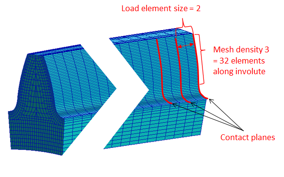
Figure 63 Load element size
Computed Number of Load Cases
This field returns the number of load cases that are calculated in the Nastran Solution 101 what is proportional to the rank of tooth stiffness matrix. This number is proportional to the value of Mesh density and Number of Contact Planes.
Say, for Mesh Density = 2 there are 24 load elements along involute; let’s take 20 Number of Contact Planes =>
(24+1) * (20 + 1) = 525 load cases
Display Ratio Lead
It controls resolution of geometrical representation of a gear element in Adams View. It defines the number of FE elements per one shell geometry element in lead direction. The input value of 1 means fine, 2 is for normal and 3 for coarse resolution for the shell graphics.
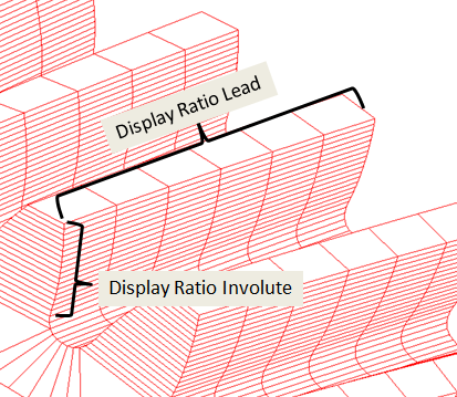
Figure 64 Display ratio involute
Display Ratio Involute
It controls resolution of geometrical representation of a gear element in Adams View. It defines the number of FE elements per one shell geometry element along involute direction. The input value of 1 means fine, 2 is for normal and 3 for coarse resolution for the shell graphics.
Number of teeth to display
It defines the number of teeth to be created for shell geometry. The purpose of this entry is to define segment of the gear wheel.
The Gear AT Mesh will be started and you will see the echo of the input data (contents of the *.opt file and *.CGP file) and the start of the actual meshing as shown in Figure 65. The option 'quiet' suppresses the output to the screen. The *.CGS file contains all information about the geometry of the tooth. If a flexible tooth has been requested, the *.CGS file will be expanded by the op2-reader with results from Nastran.
The file name of the *.CGS file and bulk data file of the gear tooth is composed as *_xxx_yy_zz.CGS and *_xxx_yy_zz.dat where:
■xxx number of contact planes
■yy mesh density
■zz load element size
The filename of the *.shl file is composed as *_xxx_yy_zz.shl where:
■xxx number of contact planes
■yy display ratio lead
■zz display ratio involute
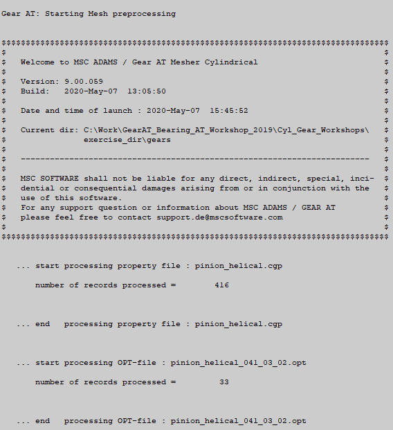
Figure 65 Start of Gear AT Mesh
Gear AT mesh also reports the results of the curve-fitting as shown in Figure 66; 'difference' shows the distance between the input point and its curve-fitted location. These values should be generally very small. Figure 67 shows the successful termination of the Gear AT Mesh.
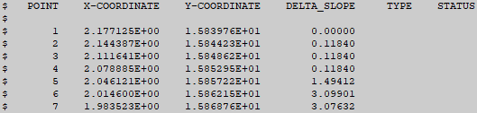
Figure 66 Results of curve-fitting
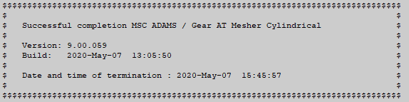
Figure 67 Termination of Gear AT mesh
If you requested generation of a flexible tooth, Nastran or ViewFlex will be launched (Figure 59 and Figure 68). Please be reminded, that the CPU-time for Nastran increases with increasing number of contact planes, mesh density and load element size.
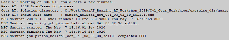
Figure 68 Launch of Nastran
The process of Figure 68 proceeds by execution of Gear AT op2-reader; see Figure 69. This processor reads the data stored by Nastran in the *.op2 file and appends retrieved data to the *.CGS file.
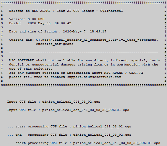
Figure 69 Execution Gear AT op2-reader
If Nastran computation was not successful, Gear AT op2-reader should issue an information message and indicate unsuccessful termination. Please check the *.f06 file and mesher.log file; there you should find a hint about the cause of the abort by Nastran.
The button displays the contents of the *.CGP file.
displays the contents of the *.CGP file.The button  opens the Nastran bulk data file in Apex. Please, make sure you opt to Keep FE Mesh file in order to preserve Nastran input deck (*.bdf, *.dat) file. Figure 70 shows the example of mesh for a tooth.
opens the Nastran bulk data file in Apex. Please, make sure you opt to Keep FE Mesh file in order to preserve Nastran input deck (*.bdf, *.dat) file. Figure 70 shows the example of mesh for a tooth.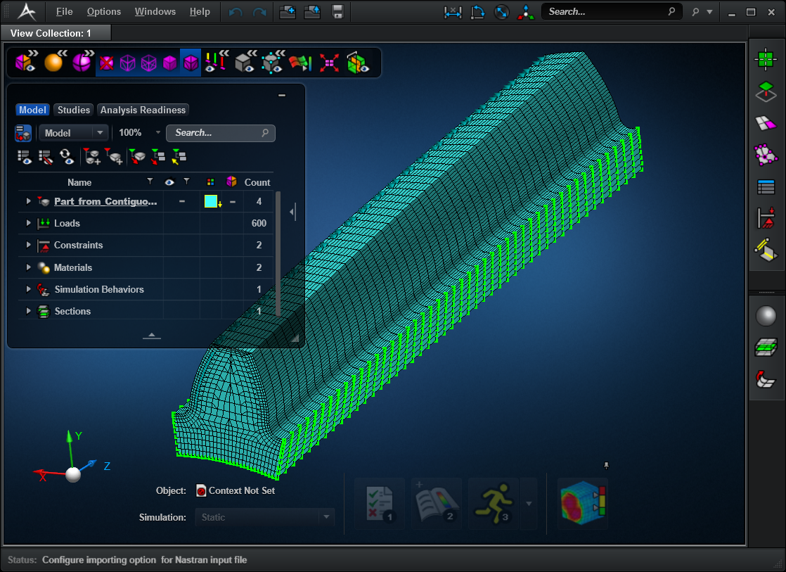
Figure 70 Nastran mesh of tooth
Flex Rim
To preprocess Full Flex Gear one has to define FE properties of a flex rim. Here you need to input FE model of wheel body in Nastran format and interface node to attach Adams flexible body to a shaft. As result you get MNF and CNT file which will be referenced in *.CGP so you can create full flex gear element in Adams.
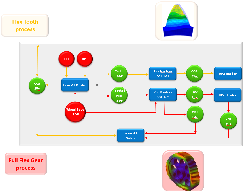
Figure 71 Flex Tooth and Full Flex Gear process
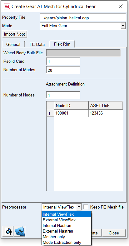
Figure 72 Gear AT mesh dialog box - Flex Rim tab
For the options | Do the following |
|---|---|
Wheel Body Bulk File | Browse for Wheel Body Bulk File in Nastran format. Important: ■MAT1 card -> DTI UNITS: MGG, N, MM, S (WTMASS = 1.0) ■RBE for attachment node - location 0.0, 0.0, 0.0 |
Psolid Card | Enter ID of PSOLID card of wheel body FE structure from Wheel Body Bulk File to make a glued contact with; see Figure 73 |
Number of Modes | Number of Fixed boundary normal modes - EIGR card Default value is 10 |
Number of Nodes | Enter number of attachment nodes. That should be at least one attachment node to fix gear to shaft. Default is 1 |
Node ID | Enter a Node ID for attachment definition Important: make sure that attachment node to a shaft has location in FE basic system = 0.0, 0.0, 0.0 and that wheel body rotation axis lies on the Z axis od FE basic system |
ASET DoF | Define degrees of freedom (DOF) to be used in the modal analysis. 1 = X-axis translation 2 = Y-translation 3 = Z-axis translation 4 = X-axis rotation 5 = Y-axis rotation 6 = Z-axis rotation For example, if you want to apply fixed joint to attachment node enter 123456. To apply spherical joint enter 123. Important: make sure you hit enter key after you define the value in table. Otherwise your value will be not applied! |
Extended definition:
Before preprocessing the Full Flex Gear element, you might find helpful to read the Adams Flex online help - see Translating FE Model Data - FE Model Requirements.
Wheel Body Bulk File
The full flex gear FE model consists of the wheel body provided by the user and toothed rim generated by the Gear AT mesher. These two FE models are joined together by Nastran glued contact. The distance below which a node is considered touching a body is set to 0.05 mm - see ERROR parameter in BCONPRG card of a *_SOL103.bdf file and read Nastran documentation.
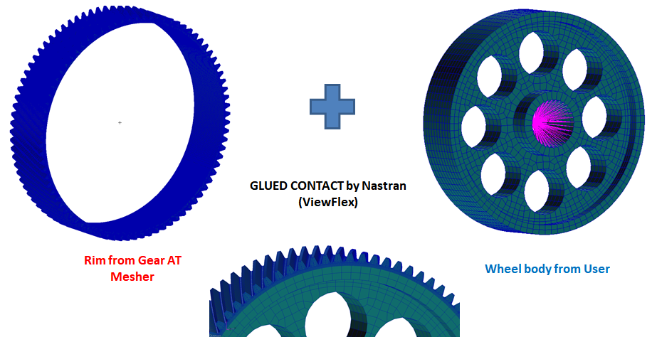
Figure 73 Flex Rim & Wheel Body glued contact
Currently there are following prerequisites for the user FE model of wheel body; see Figure 74 and Figure 75:
■Wheel body outer diameter has to match the Rim diameter of the gear defined in the Shape Definition step
■FE Origin has to be located in the middle of gear width
■Wheel attachment node has to be at FE origin [0.0, 0.0, 0.0]
■Z axis of FE basic coordinate system has to be rotational axis of a gear wheel
■There can be one gear wheel per Adams flex body
■Wheel body has to be separate from shaft FE structure
■all data have to be defined in following consistent set of units: MGG, N, MM, S (WTMASS = 1.0)
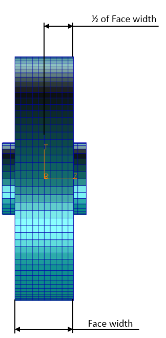
Figure 74 FE Origin location - modeling prerequisite
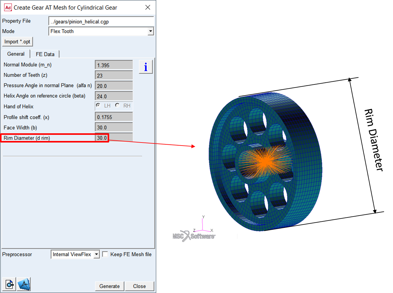
Figure 75 Rim diameter - modeling prerequisite
Please make sure your wheel body bulk file has following Nastran cards comment out; see Figure 76:
■BEGIN BULK
■EIGRL
■PARAM, AUTOMSET, YES
■PARAM, AUTOQSET, YES
■ASET / ASET1
■DTI
■ENDDATA
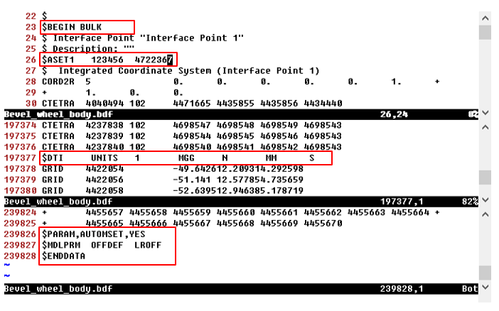
Figure 76 Wheel body BDF - Nastran cards to be removed
Psolid Card
Make sure you enter correct ID of PSOLID Nastran card of wheel body thus Nastran can make glue contact between wheel body and tooth rim; see Figure 77
Number of modes
Enter appropriate number of fixed boundary normal modes (also known as component dynamic modes) to define sufficiently large modal basis of your wheel body. Whenever possible, you should always correlate eigen frequencies of your FE model to the modal test data. Note that default value of 10 will be most probably insufficient to capture real deformations of the flexible wheel body structure.
Number of Nodes
When you create a Full Flex Gear element in your Adams model, you select reference marker on a part to attach the gear element to. Gear AT creates for you an appropriate constraint to attach gear element to the part which takes all 6 DoF. Therefore, there should be at least one attachment node (also known as interface node) defined in the MNF file.
Nodes ID
Enter the node id of a gear attachment. This node could belong either to RBE2 or RBE3 element, see Figure 77. The one which is used to attach a gear element to a shaft should be located at origin of basic system of your FE model. In order to avoid the use of “PARAM, AUTOMSET, YES” which is required for defining ASET with attachment nodes belonging to RBE3 element, there is CBUSH element created per attachment node along with coincident node which becomes so called interface node in Adams. Therefore, you will find a different ID of the interface node than specified in this table cell.
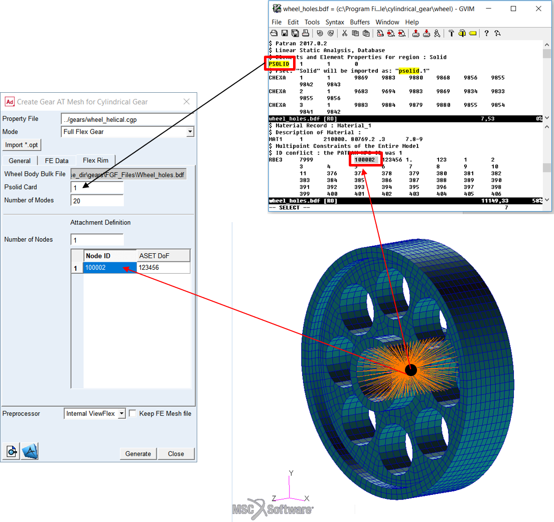
Figure 77 Wheel body BDF - Attachment node and Psolid card
ASET DoF
Enter the degree of freedom (DoF) per attachment node of your wheel body FE model. When you build a flexible body into an Adams model, you interface with the body using a variety of attachments, either joints or forces. In Adams Flex, you can model the variable boundary conditions at attachment points, which are nodes that have been idealized for attachment, by preserving all six Cartesian degrees of freedom (DoFs) of those points as you export the flexible body from your finite element analysis (FEA) program. An attachment point is equivalent to a superelement exterior grid point. Each attachment point normally contributes six modal DOF. Corresponding to each attachment point DOF is a constraint mode, which is a static mode shape due to a unit displacement of that DOF while holding all other DOFs of all attachment points fixed. A large number of attachment points can result in unwieldy data files and can significantly impact CPU time, if the associated modes are enabled during an Adams dynamic simulation. It is advised to limit number of constraint modes by prescribing adequate DoFs per attachment node. For instance, if you intend to model spherical joint, it is enough to preserve translational DoF for the ASET (123). However, the ASET for attachment of the gear element to a shaft should always preserve all DoFs (123456).
It is good practice to always verify flex body after importing to Adams View (after Gear AT element for Full Flex Gear has been created). Especially check the flexible body mass and make sure that the first 6 frequencies are very close to 0.0 Hz (rigid body modes) and ensure that all these rigid body modes are disabled. In case there are 12 rigid body modes the glue contact failed most probably due to higher distance between wheel body and toothed rim FE structures than the ERROR specified in a *_SOL103.bdf file.
For more information about verifying flexible bodies, see Building Flex Body Models - Verifying Flexible Bodies in the Adams Flex online help.