About Pacejka '89 and '94
The Pacejka '89 and '94 handling models are special versions of the Magic-Formula Tire model as cited in the following publications:
■Pacejka '89 - H.B Pacejka, E. Bakker, and L. Lidner. A New Tire Model with an Application in Vehicle Dynamics Studies, SAE paper 890087, 1989.
■Pacejka '94 - H.B Pacejka and E. Bakker. The Magic Formula Tyre Model. Proceedings of the 1st International Colloquium on Tyre Models for Vehicle Dynamics Analysis, Swets & Zeitlinger B.V., Amsterdam/Lisse, 1993.
PAC2002 is technically superior, continuously kept up to date with latest Magic Formula developments, and MSC’s recommended handling model. However, because many Adams Tire users have pre-existing tire data or new data from tire suppliers and testing organizations in a format that is compatible with the Pacejka '89 and '94 models, the Adams Tire Handling module includes these models in addition to the PAC2002.
The material in this help is intended to illustrate only the formulas used in the Pacejka '89 and '94 tire models. For general information on the PAC2002 and the Magic Formula method, see the papers cited above or the PAC2002 help.
History of the Pacejka Name in Adams Tire
The formulas used in the Pacejka '89 and '94 tire models are derived from publications by Dr. H.B. Pacejka, and are commonly referred to as the Pacejka method in the automotive industry. Dr. Pacejka himself is not personally associated with the development of these tire models, nor does he endorse them in any way.
About Coordinate Systems
The coordinate systems used in tire modeling and measurement are sometimes confusing. The coordinate systems employed in the Pacejka ’89 and ’94 tire models are no exception. They are derived from the tire-measurement systems that the majority of Adams Tire customers were using at the time when the models were originally developed.
The Pacejka '89 and '94 tire models were developed before the implementation of the TYDEX STI. As a result, Pacejka ’89 conforms to a modified SAE-based tire coordinate system and sign conventions, and Pacejka ’94 conforms to the standard SAE tire coordinate system and sign conventions. MSC maintains these conventions to ensure file compatibility for Adams Tire customers.
Future tire models will adhere to one single coordinate system standard, the TYDEX C-axis and W-axis system. For more information on the TYDEX standard, see Standard Tire Interface (STI) for PAC2002.
Contact Methods
The Pacejka '89 and '94 tire model supports all Adams Tire contact methods.
■One Point Follower Contact, used by default for 2D Road, 3D Spline Road, OpenCRG Road and RGR Road.
■3D Equivalent Volume Contact, used by default for 3D Shell Road.
■3D Enveloping Contact, can be used with all road types when the keyword CONTACT_MODEL = '3D_ENVELOPING' is specified in the [MODEL] section of the tire property file.
The contact method supplies the tire model with the (effective) road height and road plane for the tire deflection calculation.
Normal Force
The normal force Fz is calculated assuming a linear spring (stiffness: kz) and damper (damping constant cz), so the next equation holds: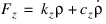
If the tire loses contact with the road, the tire deflection  and deflection velocity
 become zero, so the resulting normal force Fz will also be zero. For very small positive tire deflections, the value of the damping constant is reduced and care is taken to ensure that the normal force Fz will not become negative.
and deflection velocity become zero, so the resulting normal force Fz will also be zero. For very small positive tire deflections, the value of the damping constant is reduced and care is taken to ensure that the normal force Fz will not become negative.In stead of the linear vertical tire stiffness cz , also an arbitrary tire deflection - load curve can be defined in the tire property file in the section [DEFLECTION_LOAD_CURVE], see also the example tire property files, Example of Pacejka ’89 Property File and Example of Pacejka ’94 Property File. If a section called [DEFLECTION_LOAD_CURVE] exists, the load deflection datapoints with a cubic spline for inter- and extrapolation are used for the calculation of the vertical force of the tire. Note that you must specify VERTICAL_STIFFNESS in the tire property, but it does not play any role.
Definition of Tire Slip Quantities
Slip Quantities at combined cornering and braking/traction
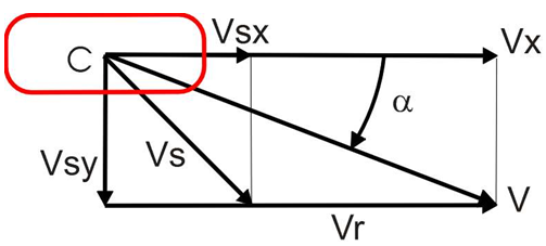
The longitudinal slip velocity Vsx in the SAE-axis system is defined using the longitudinal speed Vx, the wheel rotational velocity Ω, and the loaded rolling radius Re:
The lateral slip velocity is equal to the lateral speed in the contact point with respect to the road plane:

The practical slip quantities κ (longitudinal slip) and α (slip angle) are calculated with these slip velocities in the contact point:

and

The rolling speed Vr is determined using the effective rolling radius Re:

Note that for realistic tire forces the slip angle  is limited to 900 and the longitudinal slip Ss (= κ) in between -1 (locked wheel) and 1.
is limited to 900 and the longitudinal slip Ss (= κ) in between -1 (locked wheel) and 1.