Edit Appearance Dialog Box
Edit → Appearance
Sets how individual objects or types of objects appear in Adams View. You can set the appearance of any modeling object in your Modeling database or for a group of objects.
Learn about:
For the option: | Do the following: |
|---|---|
Entity | To explicitly specify an object, enter the name of the object whose appearance you want to set. Tips on Entering Object Names in Text Boxes. Once the name of the object is in the text box, press Enter to update the dialog box. |
Types | |
Visibility | Select how you want to set the visibility of the selected object or objects. You can select: ■On - Turns on the display of the objects. ■Off - Turns off the display of the objects. ■Inherit - Lets the objects simply inherit the display settings from its parent. For example, a coordinate system marker inherits settings from its parent part. |
Name Visibility | Select whether or not you want the name of the objects displayed in the View window. Refer to the options above for Visibility for an explanation of the choices. |
Color and Color Scope | Enter the color you want used for the objects and set which elements of the objects should be affected by the selected color. You can select: ■Polygon Fill - Sets the color of those areas of a graphic that can be shaded (they include sides of a cylinders, frustums, boxes, and so on). ■Edge - Sets the color of the lines making up the edges of the facets of a graphic that can be shaded. ■Outline - Sets the color of the lines that make up those graphics that cannot be shaded or filled like the coil of a spring damper. ■Text - Sets the color of the text. ■All - Sets the selected color for all elements of an object. To browse for a color in the Database Navigator or create a new color, right-click the Color text box, and then select Browse or Create. Below is an image of predefined colors used in Adams. Also refer Edit Color for more information. 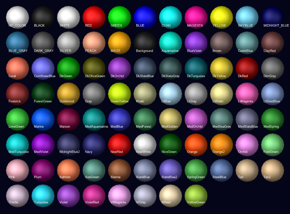 |
Render | Set the rendering for the geometry: ■Filled - Adds shading to a solid fill to give a more realistic appearance. It does not show edges. The light source is from the upper left. ■Wireframe - Shows only the edges of objects so that you can see through the objects. Helps you select points and edges. |
Transparency | Set how transparent the object or objects are. The higher the value, the more transparent the object is, allowing other objects to show through. The lower the value, the more opaque the object is, covering other objects. Note: Setting the transparency of objects can have a negative impact on graphical performance if you are using a graphics card without hardware acceleration for OpenGL. Instead of setting an object’s transparency, consider setting the object’s render mode to wireframe. |
Icon Size/Icon Scale | Enter the size you want for the icons or the amount by which you want to scale the icons. The scale factor is relative to the current size set. A scale factor of 1 keeps the icons the same size. A scale factor less than 1 reduces the size of the icons and a scale factor greater than 1 increases the size of the icons. Note that these changes take precedence over the size you specify globally for the modeling database. |