Adams View Interface
Learn about the different aspects of the Adams View interface.
Using Shortcut Menus
The four different types of Shortcut menus are explained in the table below.
To display and select a command from a shortcut menu:
1. Right-click the appropriate type of object.
2. Select the desired command.
When cursor is over: | The shortcut menu lets you: |
|---|---|
Modeling object in the main window (for example, a rigid body) | Select, modify, duplicate, delete, measure, rename, deactivate, set appearance, and display information about the object. |
Main window (over no modeling object) | Set the display of the main window, such as zoom in on your model or change the view orientation. See an Example of shortcut menu. |
Text box in a dialog box | |
Strip charts that monitor a measure | Transfer the plot to the full plotting window, display information about the measure, and delete the measure. |
Using Main Menu tools
Please refer the Main Menu section for various available tools. You can display many of them as floating dialog boxes.
As you create objects, such as parts or constraints, Adams View provides settings to assist in defining the objects. It provides the settings in a definition container at the left side of the page below the Main Menu toolbar. For example, as you create a link, Adams View lets you specify its width, length, and depth before you create it. Then, as you create the link, these dimensions are set regardless of how you move the cursor. You can also define Design variables or Expressions for these setting values.
To select a default tool from the Main Menu:
■Click the tool once with the left mouse button.
To select a default tool so you can use it several times or set the display in all view windows:
■Double-click the tool with the left mouse button.
To stop using a tool:
■Select another tool, Esc key, or the Select Tool.
Working with Text Boxes
Text boxes in dialog boxes let you input information into Adams View. Adams View text boxes provide you with a visual cue as to whether or not the information in the text box is required to run the command. If the information in the text box is required, the text box appears in a lighter shade of gray. If the information is not required, the text box appears in a darker shade of gray. Also, you can use the shortcut menu in a text box to determine if the information is required.
Learn more:
Using Shortcut Menus in Text Boxes
The text boxes also contain Shortcut menus to access commonly used commands that pertain to the information to be entered in the text box. For example, if a text box requires a file or model name, you can click the right mouse button to display a command for browsing your directories or modeling database. The types of commands that appear on shortcut menus depend on the type of object required in the text box. The table below shows the different menu commands that appear for each type of object.
When the text box requires: | The shortcut menu lets you: | |
|---|---|---|
Modeling object (for example, a rigid body) | ■Browse the Modeling database, select an object from the screen, or create an object. ■Copy, cut, and paste text. ■Manage and parameterize objects. These are the same commands available through the pull-down menus. ■Display information about the required values. |  |
File name and location | ■Browse directories. ■Search a specified path. ■Copy, cut, and paste text and display information about the required values. |  |
Text, such as a value | ■Copy, cut, and paste text. ■Parameterize the text, if appropriate. ■Display information about the required values. | 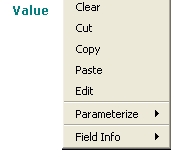 |
Entering Modeling Objects in Text Boxes
Many of the dialog boxes in Adams View require the name of a modeling object, such as a part or model. To help you enter the object name, Adams View provides commands on the Shortcut menus in text boxes for selecting the object from the screen or for browsing your modeling database using the Database Navigator.
The shortcut menu also has a command called Guesses. Guesses displays the five most recently created objects of that type. Depending on the object required, the shortcut menu also contains a command to create a new object of the required type.
To enter a modeling object by typing:
■Place the cursor in the text box, and then type the name of the modeling object in the text box.
Be sure to enter the entire name of the object, including its model and parent, if the name of the object is not unique within the entire database. For example, if you had two markers called mar_1 on two different parts, you need to enter .model_1.par_1.mar_1 to uniquely identify the marker. Learn about the Adams View modeling database hierarchy.
To enter a modeling object by picking, browsing, or creating the object:
1. Right-click the text box. The first command on the menu is the type of object to be entered. For example, the first command is Model if you are to enter a model, Constraint if you are to enter a constraint.
2. Point to the type of object and then do one of the following:
♦Select Pick and click on the desired object in the main window.
♦Select Browse to display the Database Navigator, and then select the desired object from the Database Navigator.
♦Point to Guesses and select the desired object from the list of recently created objects of that type.
♦Select Create to create an object of the type required.
Searching for Files
If a text box requires the name and location of a file, you can browse for it or look for it in a specified search path. The next sections explain how to browse and search for files:
Browsing Directories
You can use the Select File dialog box to browse for a file.
To browse for a file:
1. Right-click a text box that requires a file name to display a shortcut menu.
2. Select Browse to display the Select File dialog box.
3. Double-click the directory that contains the file.
4. In the File Name box, type the file name you want to open, or highlight the file in the list.
5. Select Open.
Tip: | Clear the text box, if necessary, and double-click to display the File Selection dialog box |
Using a Search Path
The file aview.pth in the aview directory defines search paths for different types of files. For example, there is a path defined for database modeling files (binary files), paths defined for command files, and so on. Adams View displays the search paths defined for a particular object when you select Search from a shortcut menu in a text box. You can use these search paths to quickly locate files.
To search for a file in a search path:
1. Right-click a text box that requires a file name to display a shortcut menu.
2. Point to Search, and then select a search path that contains the file you are looking for. For example, if you are searching for a modeling database (binary file), select $LOCAL_AVIEW.
The Select File dialog box appears.
3. Locate the file in the list, and then select Open.
Cutting, Copying, Pasting, and Clearing Text
You can use the shortcut menu commands that appear in text boxes to cut or copy the text in the box to the clipboard (a temporary storage area) and paste text saved in the clipboard into the text box. You can also quickly clear text in a text box using a keyboard shortcut.
To cut and copy text in a text box:
1. Select the text that you want to cut or copy.
2. Right-click the text box to display the shortcut menu and do one of the following, depending on the type of text in the text box:
3. If the text is a value, select Cut or Copy.
4. If the text is a name of an object, point to Text, and then select Cut or Copy.
To paste text stored in the clipboard:
1. Place the cursor in the text box where you want to paste the text.
2. Right-click the text box to display the shortcut menu and do one of the following depending on the type of text in the text box:
3. If the text is a value, such as a real number, select Paste.
4. If the text is a name of an object, point to Text, and then select Paste.
To quickly clear a text box:
■Left-click at the start of the text box, and then press Ctrl-k.
Viewing and Validating Text in Text Boxes
To help you ensure that you enter the correct type of information and to see if the information is required, the Shortcut menus in text boxes contain a submenu called Field Info. Field Info does the following:
■Indicates whether or not the information in the text box is required to execute the command. The following text appears in the menu. They are for information only and do not execute a command.
■Required appears if the information is required.
■Optional appears if the information is not required.
■Displays the type of information you should enter (text, integer, model, and so on).
■Validates the information you have entered in the text box. This is particularly helpful if you entered a function in the text box. Adams View also automatically validates the information when you move the cursor out of the text box.
To view and validate the information required in a text box:
1. Right-click the text to display the shortcut menu.
2. Point to Field Info, and then do either of the following:
■To verify that the information you already entered was correctly enter, select Validate. If you enter invalid information, Adams View highlights the text box in red and displays an error message.
■View the type of information to be entered and whether or not it is required for Adams View to execute the command.
Also see Entering Unit Measurements in Text Boxes.
Working with the Coordinate Window
You can use the Coordinate window to help you identify the coordinates of any location in a View window. You can also measure the distance between objects based on their coordinate locations.
The sections below explain how to work with the coordinate window:
Displaying the Coordinate Window
To toggle on and off the display of the coordinate window, do one of the following:
■On the View menu, select Coordinate Window.
 .
.The coordinate window appears in the lower right corner of the screen. You can move and size it as you do any window in your operating system.
Tip: | Press the F4 key to toggle the display of the coordinate window. |
Measuring the Distance Between Points
In Delta mode, you can use your mouse and the coordinate window to find the distance between two points
To measure the distance between two points:
1. Move the cursor to the point in a view window where you want to begin, and press and hold down the mouse button.
2. Drag the cursor to the next point. As you drag the cursor, Adams View displays the distance the cursor moves in the coordinate window.
3. To end delta mode, release the mouse button.
Using Tables to Enter Values
Adams View has two types of tables for entering values as shown in the table below. To learn more, click:
The table: | Lets you: | Example: |
|---|---|---|
Enter values for all types of objects. |  | |
Enter values for multiple locations, such as the locations for the points on a spline. |  |
Entering Values in Cells
To enter values in a cell of a table:
1. Click the cell.
The text cursor appears in the cell.
2. Enter the values in the selected cell.
Moving Between Cells
You can quickly move from one cell to another using the following shortcuts. Note that you must press the Enter key to enter information into the cells.
To move to the next cell:
■Press Tab.
To move to the previous cell:
■Press Shift + Tab.
To move up to the previous row or down to the next row:
■Press the up or down arrow keys.
Selecting Cells and Rows
To work with information in a table, you must select the information you want to change.
To select: | With the mouse: |
|---|---|
A cell | Click the cell. |
A range of cells | Click the upper left cell and drag across the cells you want to select. OR: Hold down the Ctrl key and select individual cells. |
An entire row | Click the row header. |
An entire column | Click the column header. |
Cutting, Copying, and Pasting Text in Cells
You can cut or copy text from one cell of a table and paste it in another cell.
To cut or copy text:
■Right-click the text in the cell that you want to cut or copy and then select Copy or Cut.
To paste text:
■Right-click the cell where you want to insert the text, and select Paste.
Viewing Entire Contents of a Cell
Often, information displayed in a cell is longer than the width of the cell. When this happens, Adams View displays an arrow next to the cell to indicate that there is more information than can fit in the cell. The following figure shows the Location Table as it appears in Linux when cells contain more information than can be displayed at once.
To view the rest of the cell:
■Click the cell.
Adams View displays the last portion of the information in the cell.
Resizing Columns
You can change the size of any column in a table. In addition, in the Location table, you can resize all columns equally.
To resize a column:
1. Point to the right border of the column heading that you want to resize. The cursor changes to a double-sided arrow.
2. Drag the cursor until the column is the desired size.
3. Release the mouse button

 Undoing and Redoing Operations
You can undo the effects of most Adams View commands. Adams View remembers up to 20 Adams View operations. For example, if you accidentally delete a joint, you can undo the deletion by selecting Undo. Note that you cannot undo the effects of some commands, such as the commands in the File menu.
To undo an operation, do one of the following:
■On the Edit menu, select Undo.
■Type Ctrl + Z.
To redo an operation, do one of the following:
■On the Edit menu, select Redo.
■Type Ctrl + Shift + Z.
Canceling Operations
You can cancel any operation that you started in Adams View. For example, you can exit from a dialog box or from a drawing operation or stop a simulation or animation.
To cancel an operation, do one of the following:
■Select the Cancel button on a dialog box, if available.
 .
.Managing Messages
Types of Messages
Adams View displays informational messages, errors, warnings, and faults in the following interface elements.
The element: | Displays: |
|---|---|
Informational status messages, brief descriptions of commands, and the time remaining in an operation. It also displays messages to assist you in creating and editing objects. Be sure to watch it as you work with Adams View. The status bar appears at the bottom of the main window | |
Alert boxes | Errors or messages about the command that you selected. For example, it appears when you select to perform an operation on an object and there are no objects of that type in the database. |
Messages about the execution of a command. By default, the message window only displays messages about commands you execute from the user interface. You can also set it to display messages about commands that you execute from the Command Window, Command Navigator, and Adams View command file. |
Setting the Messages Displayed
By default, the Message Window only displays error and fatal messages and messages from commands that you execute from the user interface (for example, menus and dialog boxes). You can also display messages that you execute from the Command Window, Command Navigator, and Adams View command file. In addition, you can set the severity level of the messages displayed, from informational to fatal messages.
To set the messages displayed in the message window:
1. From the Message window, select Settings.
The Message Settings dialog box appears.
2. Set the messages that you want displayed as explained in the table below, and then select OK.
To display: | Select one of the following: |
|---|---|
Only certain types of messages | ■Only Graphical User Interface (GUI) widgets to display messages that are generated from commands you execute from the user interface. ■The GUI, the command line, and command files to display messages that you execute from the user interface, command window, Command Navigator, and command files. ■Don't display messages to turn off the display of all messages. |
Messages at or above a specified severity level | ■Information - Displays messages about what is occurring during a command. Setting the message window to display these types of messages helps you understand what is happening in Adams View but requires no action from you. ■Warning - Displays messages that warn you that something unusual occurred but the operation can continue. You may want to fix or change something to complete the operation without warnings. ■Error - Displays messages that indicate that the operation cannot be executed. You need to fix or change something to complete the operation. ■Fatal - Displays messages that indicate that a programming error occurred. You should report the message to MSC's Technical Support staff. |
Clearing the Message Window
Each time you receive a message in the Message Window, Adams View adds the message to the bottom of the message window without removing the previous message. You can, however, clear all previous messages.
To clear the message window:
■From the Message window, select Clear.
Setting Screen Icon Display
When you first start Adams View, it displays Screen icons. As you add objects to your model, however, these icons can clutter your view of the model. To clear the display of a window, you can turn off the icons. You can select to turn off:
■All icons
■Only icons of certain types of objects, for example, all joints
■Only icons for individual objects, such as FORCE_1
In addition, you can set the size of the icons either in current units or as a factor of their current size.
Learn more about how to set the display of screen icons by database and object type.
For information on quickly toggling the display of all screen icons, see Displaying View Accessories. For information on setting the display of icons for individual objects, see Setting Object Appearance.
Setting Screen Icon Display by Database
You can set up how you want Screen icons to be displayed for an entire Modeling database. By default, all models and objects in the modeling database inherit the screen icon settings that you specify for the database. You can, however, override the inheritance for different types of objects as explained in Setting Screen Icon Display by Object Type, or for individual objects as explained in the Setting Object Appearance.
To set up the screen icon display for the entire database:
1. On the Settings menu, select Icons.
The Icon Settings Dialog Box appears.
2. Set New Value to one of the following to select whether or not you want to turn on screen icons:
■No Change - Select No Change to not change the current settings.
■On - Turns on all icons regardless of how you set the icon display for individual objects or types of objects.
■Off - Turns off all icons regardless of how you set the icon display for individual objects or types of objects.
3. In the New Size text box, enter the size you want for the screen icons. Note that any changes you make to the size of icons for individual objects or types of objects take precedence over this size setting.
4. To save the settings for each new database in the Adams View settings file (aviewBS.cmd), select Save new size as default. Learn about Saving and Restoring Settings.
5. Select OK.
To reset the screen icon display to the previous values:
■On the Icon Settings dialog box, select Reset.
Setting Screen Icon Display by Object Type
You can set up how you want Screen icons displayed for a particular type of object, such as all parts or joints. By default, all objects inherit the screen icon display options that you specify for the modeling database. You can set screen icon options for the following types of objects:
■Equations (System elements)
■Forces
■Joints
■Markers (Note that markers belong to parts and, therefore, by default, inherit screen icon display options for parts.)
■Motion
To set screen icon display options for objects of a particular type:
1. On the Settings menu, select Icons.
The Icon Settings Dialog Box appears.
2. Set Specify Attributes for to the type of object for which you want to set the screen icon options.
3. From the Visibility area of the Icon Settings dialog box, select whether or not you want to turn on screen icons for the selected object type. You can select:
■On - Turns on the display of screen icons for the selected type of object.
■Off - Turns off the display of screen icons for the selected type of object. Remember, however, that turning on the display of screen icons for the entire database overrides this setting.
■Inherit - Lets the object type simply inherit the display settings from its parent. For example, a coordinate system marker inherits settings from its parent part.
■No Change - Does not change the current settings. Lets you make changes to other display options without affecting the visibility of the icons.
4. Enter the size you want for the icons or select the amount by which you want to scale the icons. The scale factor is relative to the current size set. A scale factor of 1 keeps the icons the same size. A scale factor less than 1.0 reduces the size of the icons and a scale factor greater than 1.0 increases the size of the icons. Note that these changes take precedence over the size you specify globally for the modeling database.
5. Enter the color you want to use for the icons.
To browse for or create a color, right-click the Color text box, and then select Browse or Create.
1. Set Name Visibility Option to whether or not you want the names of objects of the selected type displayed in the view. Refer to Step 3 for an explanation of the choices.
2. Select OK.
Display Options
Setting Part Display
You can set a View window so it displays a particular part in the current Model. You will find this helpful when you want to compare or work with different parts at the same time.
To display a single part in a view window:
1. Click the view window in which you want to display the part.
2. On the View menu, select Part Only.
The Database Navigator appears listing the parts in the current model.
3. Select the part you want to display.
4. Select OK.
The selected part appears in the currently active view.
Displaying View Accessories
When you first start Adams View, it displays several accessories to help you manage the view of your model:
To use a dialog box to toggle on and off the display of view accessories:
1. Click the view window whose accessories you want to change.
2. On the View menu, select View Accessories, and then select the accessories that you want to turn on or off from the View Accessories dialog box that appears.
3. Enter the title you want displayed in the currently active view window, and then press Enter.
4. On the Window menu in the View Accessories dialog box, select Exit.
To use tools in the Main menu to toggle on and off the display of view accessories:
1. If you want to change the view accessories for only one view window, click that view window.
2. On the Main Menu, from the Status Toolbar  , select a view accessory tool. Double-click any of the tools to apply the accessory changes to all view windows. Note that the tool must be on top of the tool stack to double-click it.
, select a view accessory tool. Double-click any of the tools to apply the accessory changes to all view windows. Note that the tool must be on top of the tool stack to double-click it. 3. Select the buttons Icons or Grid on the Main toolbox to toggle on and off the display of screen icons and the working grid.
Tip: | ■Type a lowercase g while the cursor is in the view window to toggle on and off the display of the working grid in the active view window ■Type a lowercase v to toggle on and off the display of screen icons. |
Setting Rendering Mode
Adams View provides six Rendering mode in which you can display a model in a view window.
To select a rendering mode:
■Click the View window whose rendering mode you want to change.
■On the View menu, point to Render Mode, and then select a rendering mode.
To toggle the display between wireframe and smooth-shaded mode:
Do one of the following:
■Type an uppercase S in the view window.
Displaying Toolbox and Toolbars
You can turn on and off the display of the Model Browser, the Ribbon and Status Toolbar. You can also set where the Standard and status toolbars appear—either at the top of the main window under the menu bar or at the bottom of the window.
To turn toolbars on and off:
1. On the View menu, select Toolbox and Toolbars.
The Toolbar Settings dialog box appears.
2. Select the visibility of each toolbar and its placement in the main window. Your changes take place immediately.
3. Close the dialog box.
Setting Stereo Viewing
You can set up stereo viewing. Stereo viewing is available on all Linux platforms but not Windows.
To run stereo viewing, before running Adams View, set the MDI_STEREO environment variable MDI_STEREO (setenv MDI_STEREO 1). See Adams View Environment Variables for more information.
Stereo viewing is only available when running Native OpenGL graphics with the OpenGL_Software_Assisted registry setting set to disabled. You use the Registry Editor.
To set this registry setting:
1. From the Adams Toolbar, right-click the Toolbar tool  , and then select Registry Editor.
, and then select Registry Editor.The Registry Editor appears.
2. Select AView -> Preferences -> Graphics -> OpenGL_Software_Assisted.
Using Stereo Viewing on SGI Machines
There are two types of stereo views available on SGI machines:
■Above-and-below viewing - The first, and least useful, is above-and-below viewing. This type of viewing is used with non-stereo- ready hardware and splits the screen into two halves, a top half and bottom half. The result is that the screen size in pixels is effectively cut in half in the vertical direction. For example, on a monitor set for a screen size 1024 x 768 pixels, the screen size changes to 1024 x 384. This changes the aspect ratio of the screen and of the resulting images displayed within Adams View and Adams PostProcessor. They appear to be one half as tall as they should be.
■Interlaced stereo viewing - The second type of viewing is Interlaced stereo viewing, which is available on stereo-capable graphics cards. This approach has the advantage that the screen aspect ratio is not changed and, therefore, the resulting images maintain the same proportions has their non-stereo counterparts. To enable this mode in the current Adams code, the video format for the monitor must be set to a format that supports interlaced stereo viewing. To do this, use the SGI setmon(1) shell command. For example, on a SGI tezro machine with a V12 graphics card, you could use the following command:
/usr/gfx/setmon -n 1280x1024_100s
To turn on stereo viewing and set options for it:
1. From the Settings menu, select Stereo Viewing.
2. Select Stereo viewing.
3. Set the following options as desired:
For the option: | Do the following: |
|---|---|
Depth of Field | Slide to control the depth of the perspective matrix. |
Eye Separation | Slide to control of offset between the left and right modeling views. |
Parallax | Control the type of parallax view used to display the model: ■Positive - Positive parallax viewing produces images that appear to be within the space of the monitor. For engineering purposes where objects are often cut off by the window borders or partially obscured by dialog boxes, positive parallax viewing produces images that are less confusing to the viewer and are, therefore, easier to view. ■Negative - Negative parallax viewing produces images that appear to float in space in front of the display. Viewing floating images that are partially obscured by interface items produces confusing cues to the viewer. While the image appears in front of the screen, the interface items appear to be on the screen but these interface items can obscure part of the image. These conflicting inputs can be confusing and lead to extra strain. |
Eye Position | Use with Negative parallax viewing and use it to control how far the image floats in front of the screen. |
Setting View Background Colors
By default, Adams View uses a blue background to display the Main window and any View window that you create. It also provides a set of colors in which you can display the background. You can set the view to any color by setting the red, green, and blue colors directly.
Learn more:
Selecting a Preset Background Color
You access the palette of background colors using:
■View Background Color command on the Settings menu.
■Background color on the Status Toolbar.
The View Background Color command contains all the pre-set colors, while the Background Color tool stack contains only four of the most commonly used colors.
To select a color from the Background Color Status Toolbar:
■Select a color from the Background Color tool stack.
To select from the entire palette of background colors:
1. From the Settings menu, select View Background Colors.
The Edit Background Color dialog box appears.
2. Select a color from the palette of preset background colors.
The color appears in the Current color box and its color values appear in the Red, Green, and Blue color value sliders.
3. Select OK.
Creating a Background Color
You can create a background color by setting its red, green, and blue light percentages and change the background of all view windows to this new color. You cannot add the color to the preset palette of colors or change the colors in the preset palette.
To create a color:
1. From the Settings menu, select View Background Colors.
The Edit Background Color dialog box appears.
2. If desired, select a color near to the color that you want to create from the palette of preset background colors.
The color appears in the Current color box, and its color values appear in the Red, Green, and Blue color value sliders. Adams View creates the color by mixing the red, green, and blue light percentages as specified in the color value sliders.
3. Change the color values for the color in the Red, Green, and Blue color value sliders, as desired.
As you change the color values, the New color box changes to reflect the new values.
4. Select OK.
To reset a color to the original background color:
■Select the R tool in the Edit Background Color dialog box.
Setting Up the Working Grid
By default Adams View displays a Working grid. You can set the appearance of various elements in the grid, such as its color, location, and orientation.
Learn more:
Setting Up the Appearance of the Working Grid
Settings → Working Grid
You can set the appearance of various elements in the Working grid and toggle their visibility. You can also set the working grid to represent Polar working grid or Rectangular working grid coordinates.
To set the appearance of the working grid:
1. Do one of the following:
■On the Settings menu, select Working Grid.
The Working Grid Settings dialog box appears.
2. Select whether or not you want to display the working grid.
3. Select the type of working grid you want to use (Rectangular or Polar). Adams View changes the coordinate system settings accordingly. For more information on coordinate systems, see Setting Default Coordinate System.
4. Select the size and spacing of the working grid. The options for setting the size and spacing depend on the type of working grid you select, as listed below.
■For a rectangular working grid, set the following:
Size - Enter the size of the grid in the x and y directions in length units.
Spacing - Enter the spacing between each point in the grid in the x and y directions in length units.
■For a polar coordinate system, set the following:
Maximum Radius - Enter the radius of the working grid from its origin to its outermost circle.
Circle Spacing - Enter the amount of space between each circle in the working grid. The smaller the spacing, the more circles Adams View defines.
Radial Increments - Enter the number of lines radiating from the origin of the working grid. Adams View spaces the lines equally around the working grid. The lines do not include the axes. The number of lines (N) determines the angle increment between lines (q), as shown in the formula:
θ = 360×/N
For example, if you specify 8 lines, the angle increment between the lines is 45.
5. Select the color and weight (thickness) of each object in the grid. You can also set the color of the objects to Contrast, which indicates that Adams View should select a color that contrasts with the color currently set for the view background. Setting the color to Contrast is particularly helpful when you set each of your view windows to a different background color or when you frequently change the view background.
The colors listed for the working grid elements are the same colors provided for setting the color of objects. The colors do not include any new colors that you created.
The weight values are from 1 to 3 screen pixels.
6. Select OK.
Setting Up the Location and Orientation of the Working Grid
You can set the center location and orientation of the Working grid as desired. This is particularly helpful when you are moving or creating objects because, by default, Adams View moves and creates objects in the plane of the working grid.
To set the location and orientation of the working grid:
1. Do one of the following, if you haven't already:
■On the Settings menu, select Working Grid.
 .
.The Working Grid Settings dialog box appears.
2. Set the center location of the working grid by setting Set Location to one of the following:
■Global Origin to set the center location of the working grid to the center of the view window.
■Pick and click a location on the screen to set as the center of the working grid.
3. Set Set Orientation to how you want to orient the working grid. You can set its orientation by picking points or by aligning it with the screen plane. Note that if you select Pick for orientation, you will also set the location of the working grid.
View Options
Setting Up the Window Layout
By default, Adams View displays the front of your model in the entire main window. Adams View also provides 12 View window layouts for the Main window. The layouts vary from a single view window of your model up to six windows. Each window displays a different view of your model. Adams Views displays the current model (if there is one) into any of the views that are empty.
You select the layout you’d like for your main window from a palette of layouts or from the Window Layout Tool Stack on the Main Toolbox. The palette and tool stack contain the same set of view layouts. If you display the palette, you can keep it open so that you can quickly select another layout.
To select a layout:
1. Do one of the following:
■On the View menu, select Layout to display the Window Layout palette.
■Select the Window Layouts tool stack.
2. Select a layout.
3. If you used the palette, select Close to close it. You can keep it open to quickly switch between layouts.
Activating a View Window
By default, Adams View changes the display of your model only in the active View window, leaving the other windows the same. The active window is outlined in red. Adams View also provides shortcuts from the Tool stacks that let you change the display in all your view windows at once.
To activate a view window so that any display changes occur in it:
■Click anywhere in the view window using the left mouse button. Be sure the border changes to red.
Changing the View in a Window
Adams View provide seven pre-set views of your model that you can display in any of your view windows. You can access the pre-set views using the Pre-set command on the View menu or using the set of View Orientation Tool Stacks on the Main Toolbox.
Learn about the different Orientations and the tools that activate them.
To set a view in a view window:
1. Click the view window whose view you want to change.
2. Do one of the following:
■On the View menu, point to Pre-Set, and then select a view.
■On the Main toolbox, select one of the tools on the View Orientation tool stacks.
3. Double-click any of the tools to apply the view orientation to all view windows. Note that the tool must be on top of the tool stack to double-click it.
Tip: | Type one of the following uppercase letters while the cursor is in a view window to change to the corresponding view: ■F - Front view ■T - Top view ■R - Right view ■I - Iso |
 Setting the Center of a View Window
You can move a particular point in your model to the center of the current View window. This is particularly helpful when you have zoomed in on your model and you want to rotate the View because it lets you set the center about which Adams View rotates the view. You can also reposition the model so that the origin (0,0) of the window is again at the center of the window.
To set a particular point as the center of window:
1. Do one of the following:
■On the View menu, point to Position/Orientation, and then select Center.
Tip: | Type a lowercase c. |
2. Click the left mouse button on the point in the model that you want at the center of the window.
To return the origin (0,0) of the window to the center of the window:
■On the View menu, point to Position/Orientation, and then select Origin.
Setting the View Perspective
By default, Adams View displays your model as though it were drawn on a flat piece of paper. This is called orthographic projection mode. You can change the depth of the screen to perspective mode. Perspective mode causes a vanishing point effect by showing the size of parts relative to their distance from the viewer. It does not show the true proportions of all parts. The figure below shows a solid box in the two different view projection modes. Once in perspective mode, you can set the distance the objects are from the viewer.
To set the current View to perspective mode, do one of the following:
■On the View menu, point to Projection, and then select Perspective.
To set the perspective in the window:
Tip: | Type a lowercase d to change the perspective. |
2. Place the cursor in the view window and click and hold down the left mouse button.
3. Drag the cursor in the window as follows:
■To increase perspective, drag the cursor upward.
■To decrease perspective, drag the cursor downward.
4. When the window contains the desired perspective, release the mouse button.
To set the view back to orthographic mode, do one of the following:
■On the Main toolbox, clear the Depth check box again.
■On the View menu, point to Projection, and then select Orthographic.
 Dynamically Translating a View
To move the display of the model so that you can see objects that are outside the current view window boundaries, you can translate the view. Translating the view moves the view in the x and y directions as you move the cursor. You can also more precisely control the translation of the view by specifying the amount by which Adams View translates the view each time you move the cursor.
You can translate the View by selecting the Translate command from the View menu or View shortcut menu that appears in the main window. In addition, there is a Translate tool on the Main toolbox. If you want to control the amount by which Adams View moves the view, you must use the Translate tool on the Main toolbox.
To dynamically translate the view:
1. Do one of the following:
■On the View menu, point to Position/Orientation, and then select Translate.
2. Place the cursor in the view window and click and hold down the left mouse button.
3. Drag the cursor in the window in the direction you want to translate the view. The view of the window follows the movement of the mouse.
4. When the window contains the desired view, release the mouse button.
Tip: | Type a lowercase letter t while the cursor is in a view window. |
To dynamically translate a view by specified increments:
Use the Translate tool on the Main toolbox as explained above, but also:
1. On the Main toolbox, in the Increment box, enter the amount by which you want to increment the view translations.
2. As you translate the view, hold down the Shift key. Holding down the Shift key limits Adams View to the increments you specified. To translate the view continuously, release the Shift key.
Dynamically Rotating a View
You can rotate the display of the model about any of the View’s three axes (x, y, or z). You can also more precisely control the rotation of the view by specifying the amount by which Adams View rotates the view each time you move the cursor. All the rotation operations work using screen axes. Screen axes are fixed with x to the right, y up, and z out of the screen.
You can rotate a view the Position/Orientation submenu on the View menu or from the View shortcut menu. In addition, you can use the View Manipulation Strip on the Main Menu to rotate the view about the screen x-, y-, and the z-axes. If you want to set the amount by which Adams View rotates the view, you must use the Dynamic Rotation tool stack on the Main toolbox.
To rotate a view dynamically:
1. Do one of the following:
■On the View menu, point to Position/Orientation, and then select one of the Dynamic Rotation commands.
■Select a tool from the Dynamic Rotation tool stack on the Main toolbox. Select either:
Rotate XY tool  to rotate the view about the screen’s x- and y-axes at the same time.
to rotate the view about the screen’s x- and y-axes at the same time.Rotate Z tool  to rotate the view about the screen’s z-axis.
to rotate the view about the screen’s z-axis. 2. Place the cursor in the view window, hold down the left mouse button, and move the cursor to rotate the view in the specified direction. As you move the cursor, the view changes.
3. When the window contains the desired view, release the mouse button.
Tip: | Type a lowercase r while the cursor is in the view window to rotate the view about the x- and y-axes and type a lowercase s to rotate (spin) the view about the z-axis. |
To dynamically rotate a view by specified increments:
Use a Dynamic Rotation tool on the Main toolbox as explained previously, but also:
■On the Main toolbox, in the Increment box, enter the amount by which you want to increment the view rotations. You can enter any value, but we suggest that you use a value between 0 and 360. Try 5.
■As you rotate the view, hold down the Shift key. Holding down the Shift key limits Adams View to the increments you specified. To rotate the view continuously, release the Shift key.
 Orienting the View Using an Object XY
You can rotate the View to that of any object in your model. Adams View rotates the view so that the front of the selected object appears in xy plane of the view. The front of an object is the location where its positioning handle is set to the screen axes. For example, if you have two blocks as shown in the following figure, you can orient the view to the front of BLOCK_1 simply by selecting any part of BLOCK_1.
To orient the view using an object:
1. Select one of the following:
2. Select an object.
Tip: | Type a lowercase e when the cursor is in the view window. e stands for entity orient. |
 Orienting the View Using Three Points
You can specify three points to define a new View orientation in the View window. The first point defines the center of the view and the second and third points define the x- and y-axes. You can define the points for the x- and y-axes using any edge, face, or point in your model.
For example, if you have two blocks as shown in the figure below, you can rotate the view to see the front of the first block, BLOCK_2, by selecting the center of mass of BLOCK_2 as the center of the view and selecting two points along the edges of BLOCK_2 that define the new view. In the figure, the points that you would select are indicated with X’s.
To orient a view using three points:
1. Do one of the following:
2. Select the point you want to define as the center of the view.
3. Select an edge, face, or point to define the x-axis and then select another edge, face, or point to define the y-axis.
Adams View rotates the view to the new view.
 Dynamically Zooming the Display
Changes the magnification of your model in the window. Dynamic zooming automatically zooms the current window in and out as you move the cursor. You can more precisely control the magnification by specifying an increment by which Adams View zooms the window.
To dynamically zoom the current window:
1. Select one of the following:
■On the View menu, point to Position/Orientation, and then select Zoom In/Out.
2. Position the cursor in the window you want to zoom and hold down the left mouse button.
3. Move the cursor in the window:
■To enlarge the display of the model, move the cursor toward the outside of the window. Do not move the cursor outside of the window or Adams View turns dynamic zooming off.
■To shrink the display of the model, move the cursor in toward the center of the window.
4. When the model is at the desired magnification, release the mouse button.
Tip: | Type a lowercase z while the cursor is in the window to dynamically zoom the view. |
To dynamically zoom the window by increments:
1. On the Main Menu, in the Increment box, enter the amount by which you want to increment the zoom. For example, to magnify the view 3 times, enter 3. To magnify it by 1/2, enter.5.
2. As you move the cursor in the window, hold down the Shift key.
Zooming In and Out by Pre-Set Values
You can quickly enlarge and shrink the display of the model in the current window by 1/2 (50%) its current magnification.
To magnify the display by 1/2:
■On the View menu, point to Position/Orientation, and then select Zoom In.
To shrink the display by 1/2:
■On the View menu, point to Position/Orientation, and then select Zoom Out.
 Fitting a Model in a Window
You can fit the entire model into the current window using the Fit and Fit - No Ground commands.
■Fit - Fits the entire model into the window, including the ground part and any geometry attached to it.
■Fit - No Ground - Excludes the ground part and its geometry.
For example, if you have a model of a car that also has a very large piece of geometry on ground representing a road, and you use Fit to view the entire model, the view contains all of the geometry, as shown in the image on the left. The car appears very small after the fit to accommodate the road. If you use Fit - No Ground, the view is only of the car, as shown in the image on the right.
To fit the entire model, including ground, into the window:
Do one of the following:
■On the View menu, point to Position/Orientation, and then select Fit.
■Right-click the background of the screen, and, from the shortcut menu, select Fit to View.
Tip: | Type a lowercase f. |
To fit the model, excluding ground, into the window:
■On the View menu, point to Position/Orientation, and then select Fit - No Ground.
■Right-click the background of the screen, and, from the pop-up menu, select Fit to View.
Tip: | Type Ctrl f. |
Refreshing the Model Display
You can redraw the Main window to return the model to its initial configuration and display all geometry in the Model. This is particularly useful if you selected to view only certain parts and now want to view the entire model.
To refresh the model display:
■On the View menu, select Refresh.
Purging Cache Files
Flexible-body cache files (.fcf) used to achieve the performance of flexible-body animations can accumulate on your disk after repeated simulation-animation iterations. You can purge the cache files from your disk through the Tools menu in both Adams View and Adams PostProcessor (animation mode).
Learn more about cache files.
To purge cache files:
■From the Tools menu, select Purge Cache Files.