Generating Parametric Extrusions
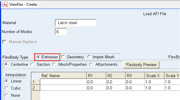
ViewFlex enables the generation of a flexible body automatically that is defined as a geometric extrusion of a section profile along a generic centerline. Using this option, rigid parts previously defined on the model to generate flexible bodies are not needed.
To generate a flexible body from an extrusion following points have to be defined:
■Centerline along which the extrusion will be created
■Geometry of the section
■Its mesh and material properties
After creating the geometry attachment points need to be defined. See section Defining Attachment Points for more information.
Accessing the Extrusion Method Options
To access the extrusion method options:
■In the ViewFlex dialog box, set FlexBody Type to Extrusion.
Defining the Centerline
When Centerline mode is selected for the Extrusion Method, the ViewFlex dialog box displays a data table in which to define the centerline, along with the extrusion to be created. Each row in the data table contains those characteristics of a reference marker, used to define the centerline path for the extrusion that can be modified. At least two reference markers have to be selected. The z-axis of these markers defines the direction of the centerline, as shown below.
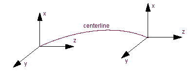 Direction of Centerline
Defining the centerline points
1. Fill the data table, as explained in the ViewFlex dialog box help.
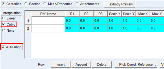
2. Set the interpolation options to control the type of interpolation between the different parts of the centerline. Interpolation methods include:
a. Linear - Linear interpolation.
b. Cubic - Cubic interpolation (may require more than two reference markers to capture curvature events).
c. None - No interpolation is used.
If you select Cubic, the Auto Align option becomes available for you to select. If you select Cubic in Adams View, ViewFlex automatically calculates the orientation of the points of the centerline (aligned along the path of the centerline). In this way, you can avoid any mesh distortion problems related to improper alignment of the centerline points. ViewFlex calculates the orientation values, but does not write them to the ViewFlex input file (AFI) nor display them in the data table. Therefore, there is no effect on the current orientation of the markers used to define the centerline.
3. Select OK.
Selecting an existing marker or construction point
■Select a cell in an existing row of the data table.
■Below the table on the ViewFlex dialog box, select Pick Coord. Reference or Browse Coord. Reference.
■From the screen or Database Navigator, select the coordinate system for which, if available, the orientation appears in the data table.
■R1, R2 and R3 are Euler angles to define the XY plane of the section. The default values are REULER values of selected Marker.
■Scale X and Y are the scale factors of each direction of the section. The default values are 1.0 respectively.
■Max X and Y are the maximum size of each direction and the out of range area is trimmed away automatically. The default values are zero (no maximum size).
The name of the entity you selected appears in the Ref. Name column of the selected row.
Marking a preview of the defined centerline
■Define the points on all of the desired rows.
■Below the table on the ViewFlex dialog box, select View Centerline Geometry.
Modeling the Section
Section modeling lets you define the section to be extruded along the previously defined centerline for the Extrusion Method. You can select:
Define an elliptical section
■In the ViewFlex dialog box, select Section.
■Select Elliptical.
The dialog box changes to display options for defining an ellipse, as shown below.
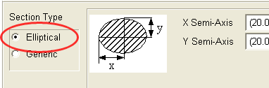
■Enter the semi-axis lengths of the ellipsoid along the x- and y-axes of the frames defining the centerline. A circular section is obtained when x = y.
Define a generic section
■In the ViewFlex dialog box, select Section.
■Select Generic.
The dialog box changes to display options for defining a generic section, as shown below
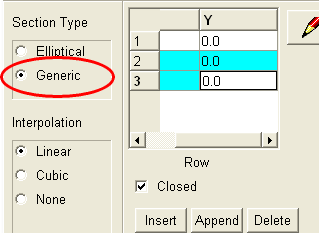
■Enter values in the X and Y columns. For information on adding or deleting rows of points, see Working with the ViewFlex Dialog Box.
■Use the Interpolation options to control the type of interpolation between the different parts of the centerline. Interpolation methods include linear, cubic, and none.
Note: | The origin of the sketch area represents the centre line point for that node. |
Preview a generic section
1. Select the Sketcher tool. 
A window appears for sketching the contents of the data table.
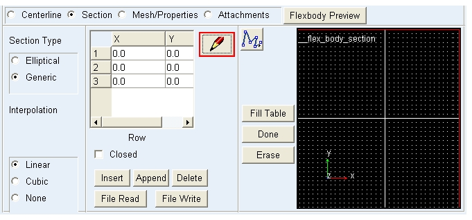
2. Select the Polyline tool to begin sketching in the window. Click the mouse at each data point. Right-click to stop sketching. 
a. To create a closed section, select Closed.
b. To transfer the sketched points to the data table, select Fill Table.
c. To erase the profile you sketched, select Erase.
3. Click on Done to close the sketch window.
Defining Mesh Types, Sizes, and Materials
For a flexible body you are creating using the Extrusion Method, you can define its mesh type (shell or solid), its dimensions, and material type.
To define the mesh:
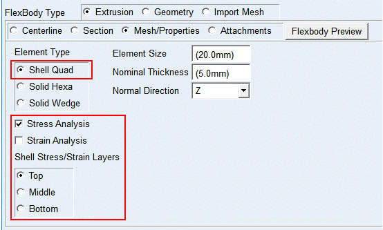
From the ViewFlex dialog box, select Mesh/Properties. Options for setting the mesh appear.
■Define the mesh as explained in Mesh/Properties topic
Previewing the Mesh of a Flexible Body
To preview only the mesh of a flexible body created using the Extrusion Method without performing the modal analysis:
■In the ViewFlex dialog box, select Flexbody preview.
ViewFlex generates a preview of the mesh of the flexible body with all the spider webs between the attachment points and secondary nodes. After mesh preview generation, Del Mesh Preview is automatically selected, so you can delete the previously generated mesh, if it does not look according to your wishes or you want to change its properties.
A message window displays the steps performed by ViewFlex during mesh creation.
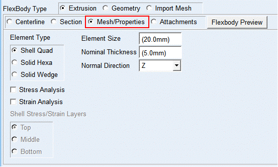
Performing Pre-Stress/Strain Calculation
During the creation of a flexible body using the Extrusion Method, stress and/or strain calculation can be selected. It is available for shell quad, solid hexa and solid wedge element. For shell elements, the surface (top, middle, bottom) can be defined on which the stress/strain is supposed to be calculated.
Note: | Adams Durability is a prerequisite for the stress/strain calculation in Adams Postprocessor. |
To calculate the stress/strain:
■While defining the mesh and material properties, select Stress Analysis and/or Strain Analysis from the ViewFlex dialog box (see below).
■For a shell, under Stress/Strain Analysis, select the layer on which you want the stress/strain calculated.