aevhybrid_shared database
ebattery_controls
Overview
This ebattery system is defined as battery pack. This is a power source to the electric motors in electric vehicle models. The battery pack is showcased as general rigid part in Adams Car and the control system GSE is used to control the regenerative braking and battery status.
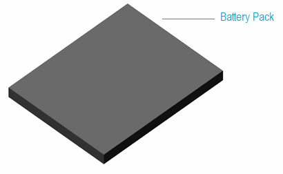
Figure 83 Battery Pack
Template name
_ebattery_controls
Major role
control_system
Application
Full-vehicle assemblies
Files referenced
Control system ECU (.dll) from EV-Hybrid shared database external_system_libraries.tbl
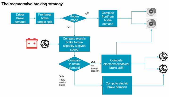
Figure 84 Flowchart of regenerative braking strategy
Based on battery state of charge, it calculates brake demand to brake system. The mechanical brake and electrical brake will be distributed based on control system logic for simulating regenerative braking application.
The SDI driver issue throttle and brake demand signals from the full vehicle event simulation. From these signals, the ECU computes the desired driving torque and braking torque to be applied to the vehicle. When throttle demand is 100% (maximum) then the driving torque applied should be 100% of the max driving torque characteristic. When the driver is braking, and the regen mode is OFF, the ECU simply transfer the brake demand to the brake system.
When regen mode is ON, the ECU computes the equivalent braking torque to be applied to the vehicle, and compares it the electric braking torque capacity (which may depend on the vehicle velocity).When the maximum achievable electric braking torque is reached, the ECU issues mechanical brake demand to the brake torque.
Communicators
The communicator: | Entity class: | From minor role: | Matching name: |
|---|---|---|---|
cis_steering_wheel_angle | solver_variable | inherit | steering_wheel_angle |
cis_brake_demand | solver_variable | inherit | brake_demand |
cis_throttle_demand | solver_variable | inherit | throttle_demand |
cis_brake_bias | real | inherit | brake_bias |
cis_power_demand_EM_front | solver_variable | inherit | power_demand_EM_front |
cis_power_demand_EM_rear | solver_variable | inherit | power_demand_EM_rear |
cis_max_torque_EM_front | solver_variable | inherit | max_torque_EM_front |
cis_max_torque_EM_rear | solver_variable | inherit | max_torque_EM_rear |
cis_longitudinal_velocity | solver_variable | inherit | longitudinal_velocity |
cis_left_front_wheel_omega | solver_variable | inherit | left_front_wheel_omega |
cis_right_front_wheel_omega | solver_variable | inherit | right_front_wheel_omega |
cis_left_rear_wheel_omega | solver_variable | inherit | left_rear_wheel_omega |
cis_right_rear_wheel_omega | solver_variable | inherit | right_rear_wheel_omega |
cos_throttle_demand_EM_front | solver_variable | inherit | throttle_demand_EM_front |
cos_throttle_demand_EM_rear | solver_variable | inherit | throttle_demand_EM_rear |
cos_brake_demand_front | solver_variable | inherit | brake_demand_front |
cos_brake_demand_rear | solver_variable | inherit | brake_demand_rear |
cos_throttle_demand_ECU | solver_variable | inherit | throttle_demand_ECU |
cos_brake_demand_ECU | solver_variable | inherit | brake_demand_ECU |
Control System Inputs/Outputs
Pinputs from Control System |
|---|
brake_demand_front |
brake_demand_rear |
throt_demand_EM_front |
throt_demand_EM_rear |
steering_wheel_angle |
throttle_demand_SDI |
brake_demand_SDI |
left_front_wheel_omega |
right_front_wheel_omega |
left_rear_wheel_omega |
right_rear_wheel_omega |
longitudinal_velocity |
max_brake_torque_front |
max_brake_torque_rear |
front_brake_bias |
front_drive_bias |
max_torque_EM_front |
max_torque_EM_rear |
electric_power_demand_front |
electric_power_demand_rear |
Notes: | Please refer following control system models created in Easy5. These are available in evhybrid_shared database under table external_system_libraries.tbl. ■battery_management_regen_ECU..ezmf ■simple_electric_motor.ezmf ■induction_motor_PWM.ezmf The control system ECU logic is as follows: 1. SDI driving torque is divided for front/rear throttle_demand_front = MIN(100,1*throttle_demand_from_SDI*front_drive_bias) throttle_demand_rear = MIN(100,1*throttle_demand_from_SDI*(1-front_drive_bias)) 2. SDI braking torque is divided for front/rear brake_demand_front = brake_demand_from_SDI*front_brake_bias brake_demand_rear = brake_demand_from_SDI*(1-front_brake_bias) 3. If regenerative flag is On then compute theoretical braking torque demand from the SDI brake demand brake_torque_demand_front=front_brake_bias*brake_demand_from_SDI/100*max_brake_torque_front brake_torque_demand_rear=(1-front_brake_bias) * brake_demand_from_SDI / 100 * max_brake_torque_rear 4. Electric motor brakes, no mechanical brake Computes part of the braking torque demand to be applied by the electric motor a. If brake_torque_demand_front is less than or equal to (abs(max_torque_EM_front) * 0.5 * final_drive_ratio)) then brake_torque_EM_front=brake_torque_demand_front/(0.5*final_drive_ratio) //*** electric brake front brake_demand_front = 0 //*** no mechanical brake front b. If brake_torque_demand_rear is less than or equal to (abs(max_torque_EM_rear) * 0.5 * final_drive_ratio)) then brake_torque_EM_rear=brake_torque_demand_rear/(0.5*final_drive_ratio) //*** electric brake rear brake_demand_rear = 0 //*** no mechanical brake rear |
Notes: | 5. Maximum electric motor brake and partial mechanical brake a. If brake_torque_demand_front is greater than (abs(max_torque_EM_front)*0.5*final_drive_ratio)) brake_torque_EM_front = abs(max_torque_EM_front) //*** electric brake front brake_demand_front =100 * (brake_torque_demand_front - brake_torque_EM_front * (0.5*final_drive_ratio)) brake_demand_front = brake_demand_front / max_brake_torque_front //*** mechanical brake front b. Similarly, for rear If brake_torque_demand_rear is greater than (abs(max_torque_EM_rear)*0.5*final_drive_ratio)) brake_torque_EM_rear = abs(max_torque_EM_rear) //*** electric brake rear brake_demand_rear =100 * (brake_torque_demand_rear - brake_torque_EM_rear * (0.5*final_drive_ratio)) brake_demand_rear = brake_demand_rear / max_brake_torque_rear //*** mechanical brake front 6. Battery management Total power demand = front motor power demand + rear motor power demand Distance travelled in km= derivative of (-VX/1E6) Energy consumed = derivative of (Total power demand/3600/1000) Autonomy = min(450, max(0.01,dist travelled in km) / (max(0.001,total energy consumed))) Autonomy = battery_energy_stored * autonomy |
ebattery_mech
Overview
This ebattery system is defined as battery pack. This is a power source to the electric motors in electric vehicle models. The battery pack is showcased as general rigid part in Adams Car. This template is similar to ebattery_controls template, except it doesn’t use GSE. Instead, this template is using Mechatronics actuators and transducers signals and the control systems are created using external system libraries.
Figure 85 Battery Pack
Template name
_ebattery_mech
Major role
control_system
Application
Full-vehicle assemblies
Files referenced
External system libraries (.esl) for battery management, ABS system and front/rear motor system is referenced from table external_system_libraries.tbl available in evhybrid_shared database.
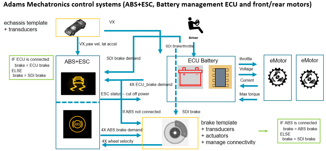
Figure 86 The signal architecture of the control systems
The ebattery_mech template have controls systems for battery management, ABS and ESC, and front/rear motors. the control system inputs and outputs are created to communicate the data between these models when simulation is running.
In ABS and ESC control system, four independent ABS channels are added based on a simple tire slip estimation. The Electronic Stability Control acting on the front brakes are based on a slip angle velocity estimation. This system takes inputs from ECU battery system if ECU is connected else it takes inputs from SDI driver. The vehicle speed, yaw rate and lateral acceleration is passed from body subsystem’s transducer signals to calculate the slip angle. The wheel speed inputs from brake subsystem to get the brake demand.
Similarly, battery management ECU system takes SDI throttle, brake demand, wheel speed, ESC status, motor power requirements to calculate the ECU brake, throttle demands and displays battery state of charge based on its usage.
Similarly, battery management ECU system takes SDI throttle, brake demand, wheel speed, ESC status, motor power requirements to calculate the ECU brake, throttle demands and displays battery state of charge based on its usage.
ABS and ESC control system inputs and outputs
N | Control System Inputs | Units |
|---|---|---|
1 | SDI_brake_demand | no units |
2 | ECU_brake_demand_fl | no units |
3 | ECU_brake_demand_fr | no_units |
4 | ECU_brake_demand_rl | no units |
5 | ECU_brake_demand_rr | no_units |
6 | wheel_speed_fl | rad/s |
7 | wheel_speed_fr | rad/s |
8 | wheel_speed_rl | rad/s |
9 | wheel_speed_rr | rad/s |
10 | body_long_vel | m/s |
11 | body_lat_accel | m/s2 |
12 | body_yaw_rate | rad/s |
N | Control System Outputs | Units |
|---|---|---|
1 | ESC_status | no units |
2 | ABS_brake_demand_fl | no units |
3 | ABS_brake_demand_fr | no_units |
4 | ABS_brake_demand_rl | no units |
5 | ABS_brake_demand_rr | no_units |
Battery Management ECU control system inputs and outputs
N | Control System Inputs | Units |
|---|---|---|
1 | SDI_steering_wheel_angle | rad |
2 | SDI_throttle_demand | no units |
3 | SDI_brake_demand | no units |
4 | SDI_transmission_demand | no units |
5 | SDI_clutch_demand | no units |
6 | wheel_speed_fl | rad/s |
7 | wheel_speed_fr | rad/s |
8 | wheel_speed_rl | rad/s |
9 | wheel_speed_rr | rad/s |
10 | ESC_status | no units |
11 | body_long_vel | m/s |
12 | body_lat_accel | m/s2 |
13 | body_yaw_rate | rad/s |
14 | max_torque_EM_front | N.m |
15 | max_torque_EM_rear | N.m |
16 | current_demand_front | no units |
17 | current_demand_rear | no units |
N | Control System Outputs | Units |
|---|---|---|
1 | ECU_brake_demand_fl | no units |
2 | ECU_brake_demand_fr | no units |
3 | ECU_brake_demand_rl | no_units |
4 | ECU_brake_demand_rr | no units |
5 | ECU_throttle_demand_EM_front | no_units |
6 | ECU_throttle_demand_EM_rear | no_units |
7 | battery_voltage | no units |
8 | battery_SOC | no units |
9 | autonomy_KM | no units |
Electric motors front and rear control system inputs and outputs
N | Control System Inputs | Units |
|---|---|---|
1 | ECU_throttle_demand | no units |
2 | rotor_velocity | rad/s |
3 | battery_voltage | no units |
N | Control System Outputs | Units |
|---|---|---|
1 | torque | N.m |
2 | max_torque | N.m |
3 | current_demand | no units |
Notes: | Please refer following control system models created in Easy5. These are available in table external_system_libraries.tbl under evhybrid_shared database. ■regen_ECU_for_adams_mechatronics.ezmf ■ABS_and_ESC_model.ezmf ■front_motor_for_adams_mech.ezmf ■rear_motor_for_adams_mech.ezmf |
ebrake_controls_system
Overview
The disc-brake system template represents a device that applies resistance to the motion of a vehicle.
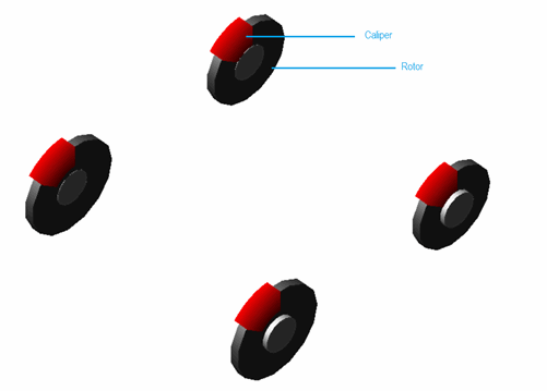
Figure 87 Brake System
Template name
_ebrake_controls_system
Major role
brake_system
Application
Full-vehicle Analysis to simulate the effect of braking on the dynamics of the vehicle.
Description
The disc-brake system template represents a simple model of a brake system. It applies a rotational torque between the caliper and the rotor. This brake system from evhybrid_shared is similar to the brake system from the acar_shared database. Except, the brake demand is communicated though the control system. For more information please refer ebattery_controls template from evhybrid_shared database.
Communicators
The front and rear brake demand input communicators are created to get the value from the output communicators of ebattery_controls template. The rest of the input and output communicators are same as brake system from the acar_shared database.
ebrake_mech_system
Overview
The disc-brake system template represents a device that applies resistance to the motion of a vehicle. This system uses Mechatronics signals.
Figure 88 Brake System
Template name
_ebrake_mech_system
Major role
brake_system
Application
Full-vehicle Analysis to simulate the effect of braking on the dynamics of the vehicle.
Description
This brake system is similar to ebrake_controls_system from evhybrid_shared database. In ebrake_controls_system, the brake demand is passed though the communicators from ebattery_controls. In this, the brake demand is passed using Mechatronics actuators and transducers signals. Please refer ebrake_mech template from evhybrid_shared database for more information.
Mechatronics Transducers Signals
The individual wheel speed is sent to battery management ECU system through run-time expressions.
The transducer signals | Takes the value: | Its units are: |
|---|---|---|
ues_cst_wheel_speed_fl | Run time expression | Angular Velocity |
ues_cst_wheel_speed_fr | Run time expression | Angular Velocity |
ues_cst_wheel_speed_rl | Run time expression | Angular Velocity |
ues_cst_wheel_speed_rr | Run time expression | Angular Velocity |
Mechatronics Actuators Signals
The individual wheel brake demand is received from the battery management ECU control system if ECU is active and ABS control system is inactive and vice versa. If both control systems are inactive then SDI brake demand is given.
The actuators signals | Takes the value: | Its units are: |
|---|---|---|
ues_csa_ABS_brake_demand_fl | Run time expression | no units |
ues_csa_ABS_brake_demand_fr | Run time expression | no units |
ues_csa_ABS_brake_demand_rl | Run time expression | no units |
ues_csa_ABS_brake_demand_rr | Run time expression | no units |
echassis
Overview
The echassis template represents the base frame of a vehicle.
Figure 89 Rigid Chassis
Template name
_echassis
Major role
body
Application
Suspensions, tires, and steering systems in full-vehicle assemblies
Description
A single rigid body part models the chassis, and a trim part mass is used to adjust the weight distribution.
Files referenced
Shell elements create the chassis graphic. All the shell files are stored in the evhybrid_shared database, in the shell_graphics.tbl directory.
Topology
The ges_chassis part is unconstrained, and the ges_trim_mass part fixed to ges_chassis.
Parameters
The rigid chassis template defines a series of parameter variables, most of which are used to compute the aerodynamic forces acting on the body. The following table lists the parameters in the template. For a detailed description of the force function,see Force Function Description..
Refer to the Rigid Chassis template for more information.
The parameter: | Takes the value: | Its units are: |
|---|---|---|
pvs_aero_drag_active | Integer | No units |
pvs_aero_frontal_area | Real | Area |
pvs_air_density | Real | Density |
pvs_drag_coefficient | Real | No units |
Mechatronics Transducers Signals
The transducer signals | Takes the value: | Its units are: |
|---|---|---|
ues_cst_body_yaw_rate | Run time expression | Angular Velocity |
ues_cst_body_long_vel | Run time expression | Velocity |
ues_cst_body_lat_accel | Run time expression | Acceleration |
Note: | The echassis template is inherited from the rigid chassis template (_rigid_chassis), but with different trim mass and shell graphic geometry. |
epowertrain_body_mounted
Overview
This epowertrain system is designed to simulate electric vehicle models. It is designed to be open and easy to understand. This epowertrain_body_mounted template is included in evhybrid_shared database. The motor torque is modelled through spline-based model. The pre-defined front/rear motor driving torque and regenerative torque is defined with the data elements in the form of motor speed vs motor torque. It is compatible with Adams Driver and quasi-static setup.
This system has also been included the rotational mass and inertia such as parts motor rotor, internal shaft and reduction gears to visually demonstrate the electric motor system. The motor body showcased as shell graphics and the mount parts are for the attachment of motor system to vehicle body and subframe.
The differential outputs for front left/right and rear left/right are connected to the suspension driveline. The Point-Torque Actuators are used to define front/rear motor torque and regenerative brake torque.
This powertrain also has the Adams Mechatronics integration to support both spline & mechatronics-based modelling. The motor torque is controlled with external control system and communicated through mechatronics transducer and actuators signals. It is designed to support co-simulation FMU.
Figure 90 Epowertrain Body Mounted System
Template name
_epowertrain_body_mounted
Major role
Powertrain
Application
Full-vehicle assemblies
Description
This powertrain can be configured as FWD, RWD and AWD using design options. The motor speed vs torque spline can be easily modified to simulate with different motor outputs. The splines can be selected in standard interface with Powertrain Parameters dialog box.
Powertrain Parameters
The vas_front/rear_motor_torque_scale_factor & vas_regen_braking_ratio is defined as Variable Actuators and not as state variables.The purpose of this is, the Variable-Actuators are easily tunable during the simulation, their expression can be activated/deactivated per mini maneuver, change as a function of time/mini-manouver or reference to a condition sensor in each mini maneuver.
Figure 91 Electric Motor Signal Flowchart
Torque state variable takes values from ebattery mech template (mechatronics) when control system is active and from spline when control system in inactive. The Mechatronics plugin’s signal manager is used, to easily connect transducer and actuator signals with control system parameters.
Files referenced
The file, emotor_torque.spl, stored in the gen_splines.tbl directory, defines the emotor speed vs torque map. The file emotor_regen_torque.spl is used to apply regenerative brake torque. The motor speed also references etransmission_spline.spl.
Topology
The epowertrain_body_mounted template contains very simple topological information because it is a functional representation of the electric powertrain. The only general rigid parts, besides the motor body, motor housing and motor shaft, are the diff outputs and the revolute joints that connect the rigid bodies to the engine body.
Parameters
The parameter: | Takes the value: | Its units are: | Integer |
|---|---|---|---|
pvs_drive_torque_bias_front | Integer | No units | Nominal percentage of drive torque sent to the front axle (1 fwd, 0 rwd) This is only used for computation of the optimum speed profile prior to the dynamic Adams simulation in case of SmartDriver event. Note: This variable is not used for distribution of torque for front and rear axle. |
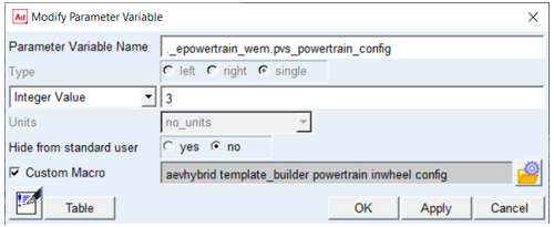
pvs_powertrain_config | Integer | No units | (1 = FWD, 2 = RWD, 3 = AWD) |
pvs_max_throttle | Integer | No units | 100 |
phs_kinematic_flag | Integer | No units | Flag that determines if kinematic joints or bushings are active |
pvs_front_motor_torque_scale_factor | Integer | No units | 0 - no torque to front motor 1 - 100 % torque |
pvs_rear_motor_torque_scale_factor | Integer | No units | 0 - no torque to rear motor 1 - 100 % torque |
pvs_epowertrain_type | Integer | No units | 1 – additional flag to define powertrain type |
Communicators
Mount parts provide the connectivity from the template to the body subsystems. Output communicators publish information, such as motor speed and etransmission spline. The following tables list the input and output communicators in the powertrain system template.
Input Communicators
The communicator: | Entity class: | From minor role: | Matching name: |
|---|---|---|---|
ci[lr]_[fr]_diff_tripot_loc | location | inherit | tripot_to_differential |
ci[lr]_[fr]_tire_force | force | inherit | tire_force |
cis_clutch_demand | solver_variable | inherit | clutch_demand |
cis_[fr]_engine_to_subframe | mount | inherit | engine_to_subframe |
cis_[fr]_powertrain_to_body | mount | inherit | powertrain_to_body |
cis_sse_diff1 | diff | inherit | sse_diff1 |
cis_throttle_demand | solver_variable | inherit | throttle_demand |
cis_transmission_demand | solver_variable | inherit | transmission_demand |
cis_regenerative_demand | solver_variable | inherit | regenerative_demand |
Output Communicators
The communicator: | Entity class: | To minor role: | Matching name: |
|---|---|---|---|
cos_drive_torque_bias_front | parameter_real | inherit | drive_torque_bias_front |
co[lr]_[fr]_tripot_to_differential | mount | inherit | tripot_to_differential |
cos_transmission_spline | spline | inherit | transmission_spline |
cos_transmission_input_omega | solver_variable | inherit | transmission_input_omega |
cos_motor_rpm | solver_variable | inherit | engine_rpm |
cos_motor_speed | parameter_real | inherit | engine_speed |
cos_max_motor_driving_torque | solver_variable | inherit | engine_maximum_driving_torque |
cos_max_motor_braking_torque | solver_variable | inherit | engine_maximum_braking_torque |
cos_max_gears | parameter_integer | inherit | max_gears |
cos_max_throttle | parameter_real | inherit | max_throttle |
cos_powertrain_type | parameter_integer | inherit | gse_powertrain_type |
Mechatronics Actuators Signals
The actuator signals | Takes the value: | Its units are: |
|---|---|---|
ues_csa_front/rear_motor_regen_torque | Run time expression | torque |
ues_csa_front/rear_motor_driving_torque | Run time expression | torque |
ues_csa_front/rear_motor_max_driving_torque | Run time expression | torque |
ues_csa_front/rear_motor_max_braking_torque | Run time expression | torque |
Mechatronics Transducers Signals
The transducer signals | Takes the value: | Its units are: |
|---|---|---|
ues_cst_front/rear_motor_deg_s | Run time expression | Angular Velocity |
ues_cst_brake_demand | Run time expression | user |
ues_cst_throttle_demand | Run time expression | user |
epowertrain_gse
Overview
This epowertrain system is mainly defined as GSE and doesn’t have any rotational parts. This epowertrain_gse template is included in evhybrid_shared database. This system can be configured with different electric motor characteristics and simulate it to evaluate the regenerative braking effects.
The only general rigid parts, electric_motor_front/electric_motor_rear and left/right diff outputs are showcased for the visualization.
The Joint-Force Actuators are used to define left/right motor torque functions.
The Adams Controls plugin is used for embedding the electric motor model and electric control unit (ECU) as Easy5 External System Libraries (ESL) and use an example of Easy5 FMU.
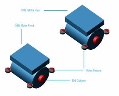
Figure 92 Epowertrain GSE System
Template name
_epowertrain_body_mounted
Major role
Powertrain
Application
Full-vehicle assemblies
Files referenced
Controls systems electric_motor_front and electric_motor_rear (.dll) from table external_system_libraries.tbl available in evhybrid_shared database.
Model and Subsystems Architecture
The SDI driver is applying the throttle and brake demands to control the vehicle during the event simulation. The throttle and brake signals are re-wired to the ECU control system. The ECU block is then computing the throttle demand to be applied to the electric motors. This demand could be positive (traction) or negative (electric braking).
According to the regenerative braking strategy, the ECU may activate the mechanical brake subsystem. When the vehicle is braking with the electric motor, the ECU block is using the recovered mechanical energy for charging the battery with a simple electric model.
The ECU and the front/rear electric motors are modelled by different Adams Controls ESL control systems. These are connected through communicators and state variables.
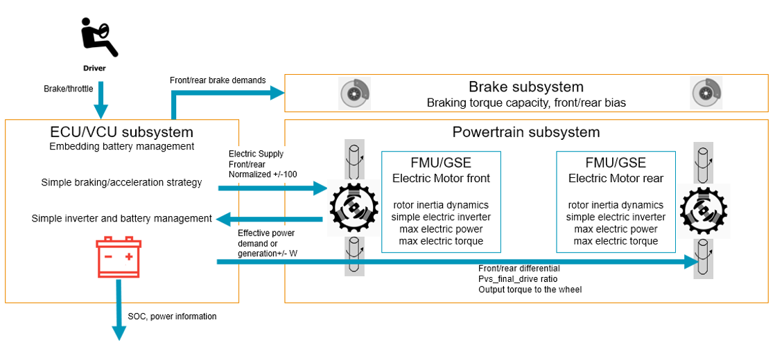
Figure 93 Overall architecture of Adams Car Electric Vehicle model
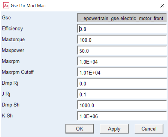
GSE motor parameters:
Parameters
The parameter: | Takes the value: | Its units are: | Integer |
|---|---|---|---|
pvs_drive_torque_bias_front | Integer | No units | nominal percentage of drive torque sent to the front axle (1 fwd, 0 rwd) This is only used for computation of the optimum speed profile prior to the dynamic Adams simulation in case of SmartDriver event. Note: This variable is not used for distribution of torque for front and rear axle. |
pvs_powertrain_config | Integer | No units | (1 = FWD, 2 = RWD, 3 = AWD) |
pvs_max_throttle | Integer | No units | 100 |
phs_kinematic_flag | Integer | No units | Flag that determines if kinematic joints or bushings are active |
pvs_motor_rev_limit | real | No units | 8000 |
pvs_motor_idle_speed | real | No units | 1000.0 |
pvs_epowertrain_type | Integer | No units | 2 – additional flag to define powertrain type |
Communicators
Mount parts provide the connectivity from the template to the body subsystems. Output communicators publish information, such as motor speed and etransmission spline. The following tables list the input and output communicators in the powertrain system template.
Input Communicators
The communicator: | Entity class: | From minor role: | Matching name: |
|---|---|---|---|
ci[lr]_[fr]_diff_tripot | location | inherit | tripot_to_differential |
ci[lr]_[fr]_tire_force | force | inherit | tire_force |
cis_clutch_demand | solver_variable | inherit | clutch_demand |
cis_[fr]_engine_to_subframe | mount | inherit | engine_to_subframe |
cis_[fr]_powertrain_to_body | mount | inherit | powertrain_to_body |
cis_sse_diff1 | diff | inherit | sse_diff1 |
cis_throttle_demand | solver_variable | inherit | throttle_demand |
cis_transmission_demand | solver_variable | inherit | transmission_demand |
cis_throttle_demand_EM_front/rear | solver_variable | inherit | throttle_demand_EM_front |
Output Communicators
The communicator: | Entity class: | To minor role: | Matching name: |
|---|---|---|---|
cos_drive_torque_bias_front | parameter_real | inherit | drive_torque_bias_front |
co[lr]_[fr]_tripot_to_differential_front/rear | mount | inherit | tripot_to_differential |
cos_motor_map | spline | inherit | engine_map |
cos_motor_idle_rpm | parameter_real | inherit | engine_idle_rpm |
cos_motor_revlimit_rpm | parameter_real | inherit | engine_revlimit_rpm |
cos_motor_stall_rpm | parameter_real | inherit | engine_stall_rpm |
cos_max_engine_driving_torque | solver_variable | inherit | engine_maximum_driving_torque |
cos_max_engine_braking_torque | solver_variable | inherit | engine_maximum_braking_torque |
cos_max_gears | parameter_integer | inherit | max_gears |
cos_max_throttle | parameter_real | inherit | max_throttle |
cos_powertrain_type | parameter_integer | inherit | gse_powertrain_type |
cos_motor_speed_gse | solver_variable | inherit | motor_speed_gse |
cos_motor_rpm_gse | solver_variable | inherit | motor_rpm_gse |
cos_diff_ratio_gse | parameter_real | inherit | diff_ratio |
epowertrain_in_wheel_electric_motor
Overview
In wheel epowertrain system is modeled to simulate electric vehicles that uses emotor directly to actuate wheels.
The in-wheel motor is a type of electric vehicle drive system. The conventional EVs feature a design where the gasoline engine is substituted with an electric motor. The In-wheel motor EV motors are installed right around each of the driving wheels to directly power the wheels.
This powertrain also has the Adams Mechatronics integration to support both spline & mechatronics-based modelling. The motor torque is controlled with external control system and communicated through mechatronics transducer and actuators signals. It is designed to support co-simulation FMU.
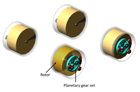
Figure 94 e-powertrain in wheel electric motors on a AWD configuration.
Template name
epowertrain_wem.tpl
Major role
Powertrain
Application
Full-vehicle assemblies
Description
This powertrain can be configured as FWD, RWD and AWD using design options pvs_powertrain config.
The motor and regenerative torque splines are defined as general data elements.
The front/rear_motor_torque_scale_factor & regen_braking_ratio are defined as parameter variables.
Torque state variable takes values from _emotor_control_wem.tpl template when control system is active and from spline when control system in inactive. The Mechatronics plugin’s signal manager is used, to easily connect transducer and actuator signals with control system parameters.
Files referenced
emotor_torque.spl, stored in the gen_splines.tbl directory, defines the emotor speed vs torque map. The file emotor_regen_torque.spl is used to apply regenerative brake torque. The motor speed also references etransmission_spline.spl.
Topology
The epowertrain_wem template contains very simple topological information because it is a functional representation of the electric powertrain.
The joint: | Connects the part: | To the part: |
|---|---|---|
jo[lr]fix_front_housing_to_knuckle | ge[lr]_front_wheel_housing | mt[lr]_front_suspension_upright |
jo[lr]rev_front_rotor_to_housing | ge[lr]_front_wheel_rotor | ge[lr]_front_wheel_housing |
jo[lr]fix_rear_housing_to_knuckle | ge[lr]_rear_wheel_housing | mt[lr]_rear_suspension_upright |
jo[lr]rev_rear_rotor_to_housing | ge[lr]_rear_wheel_rotor | ge[lr]_rear_wheel_housing |
The wheel rotor is fixed to sun gear, carrier gear is fixed to wheel housing and ring gear is attached to wheel using a fixed joint.
Parameters
The parameter: | Takes the value: | Its units are: | Integer |
|---|---|---|---|
pvs_drive_torque_bias_front | Integer | No units | Nominal percentage of drive torque sent to the front axle (1 fwd, 0 rwd This is only used for computation of the optimum speed profile prior to the dynamic Adams simulation in case of SmartDriver event. Note: This variable is not used for distribution of torque for front and rear axle.) |
pvs_powertrain_config | Integer | No units | (1 = FWD, 2 = RWD, 3 = AWD) |
pvs_max_throttle | Integer | No units | 100 |
phs_kinematic_flag | Integer | No units | Flag that determines if kinematic joints or bushings are active |
pvs_front_motor_torque_scale_factor | Integer | No units | 0 - no torque to front motor 1 - 100 % torque |
pvs_rear_motor_torque_scale_factor | Integer | No units | 0 - no torque to rear motor 1 - 100 % torque |
Communicators
Mount parts provide the connectivity from the template to the other subsystems. The following tables list the input and output communicators in the powertrain system template.
Input Communicators
The communicator: | Entity class: | From minor role: | Matching name: |
|---|---|---|---|
ci[lr]_[fr]_tire_force | force | inherit | tire_force |
cis_clutch_demand | solver_variable | inherit | clutch_demand |
ci[lr]_front_suspension_upright | mount | inherit | suspension_upright |
ci[lr]_rear_suspension_upright | mount | inherit | suspension_upright |
cis_sse_diff1 | diff | inherit | sse_diff1 |
cis_throttle_demand | solver_variable | inherit | throttle_demand |
cis_transmission_demand | solver_variable | inherit | transmission_demand |
cis_regenerative_demand | solver_variable | inherit | regenerative_demand |
Output Communicators
The communicator: | Entity class: | To minor role: | Matching name: |
|---|---|---|---|
cos_drive_torque_bias_front | parameter_real | inherit | drive_torque_bias_front |
cos_transmission_spline | spline | inherit | transmission_spline |
cos_transmission_input_omega | solver_variable | inherit | transmission_input_omega |
cos_motor_rpm | solver_variable | inherit | engine_rpm |
cos_motor_speed | parameter_real | inherit | engine_speed |
cos_max_motor_driving_torque | solver_variable | inherit | engine_maximum_driving_torque |
cos_max_motor_braking_torque | solver_variable | inherit | engine_maximum_braking_torque |
cos_max_gears | parameter_integer | inherit | max_gears |
cos_max_throttle | parameter_real | inherit | max_throttle |
cos_powertrain_type | parameter_integer | inherit | gse_powertrain_type |
Mechatronics Actuators Signals
The actuator signals | Takes the value: | Its units are: |
|---|---|---|
ues_csa_front/rear_motor_regen_torque | Run time expression | torque |
ues_csa_front/rear_motor_driving_torque | Run time expression | torque |
ues_csa_front/rear_motor_max_driving_torque | Run time expression | torque |
ues_csa_front/rear_motor_max_braking_torque | Run time expression | torque |
Mechatronics Transducers Signals
The transducer signals | Takes the value: | Its units are: |
|---|---|---|
ues_cst_front/rear_motor_deg_s | Run time expression | Angular Velocity |
ues_cst_brake_demand | Run time expression | user |
ues_cst_throttle_demand | Run time expression | user |
powertrain_hybrid_parallel
Overview
This powertrain is designed to simulate hybrid vehicle models in rear wheel drive configuration. It is designed to be open and easy to understand. This powertrain_hybrid_parallel template is included in evhybrid_shared database. This is combination of Powertrain Advanced from Adams Car concept database and epowertrain_body_mounted from EV-Hybrid shared database.
This powertrain also has the Adams Mechatronics integration to support both spline & mechatronics-based modelling. The motor torque is controlled with external control system and communicated through mechatronics transducer and actuators signals. It is designed to support co-simulation FMU.
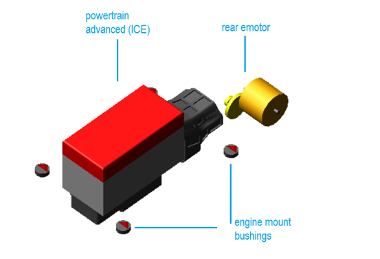
Figure 95 Powertrain_Hybrid_Parallel
Template name
_powertrain_hybrid_parallel
Major role
Powertrain
Application
Full-vehicle assemblies
Description
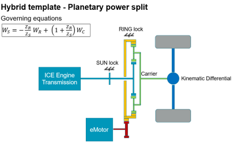
Figure 96 Hybrid Layout
This hybrid template is based on a kinematic model of a planetary gear set. The ICE engine transmission output is connected to the Sun gear. The eMotor output is connected to the Ring gear. The planetary Carrier output is connected to the kinematic differential output.
The typical planetary governing equations and parameters  ,
,  , and
, and  (gears number of teeth) are constraining the kinematic velocity ratios:
, , and (gears number of teeth) are constraining the kinematic velocity ratios: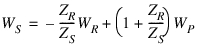
With 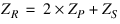
When the Sun is locked, the model is acting as a pure EV (eMotor only mode). The power flows from the eMotor to the wheel differential. The kinematic ratio is  .
.
.When the Ring is locked, the model is acting as a pure ICE (Engine only mode). The power flows from the powertrain to the wheel differential. The kinematic ratio is  .
.
.In hybrid mode, the Sun and Ring can be locked and unlocked at runtime by the Variable Actuators vas_ev_ring_lock and vas_ice_sun_lock.
When the Ring and Sun are unlocked, the model is acting as a hybrid power split layout (hybrid mode). The power flow from the eMotor and the ICE are merged by the planetary component. The kinematic ratio is variable and governed by the velocity equation.
In hybrid mode, a basic power split strategy is controlling the eMotor throttle input. The Variable Actuator vas_rpm_control is controlling the Engine speed (RPM) by adjusting the eMotor power and velocity with a simple feedback control loop (the loop gain is defined by pvs_rpm_control_gain). The eMotor throttle control can be superseded by connecting the Adams Mechatronics actuator signal ues_csa_throttle_demand_EV. The user is then able to define its own control strategy.
Files referenced
The file, emotor_torque.spl, stored in the gen_splines.tbl directory, defines the emotor speed vs torque map. The file emotor_regen_torque.spl is used to apply regenerative brake torque. The motor speed also references etransmission_spline.spl. The file, V12_engine_map.pwr stored in acar_shared database used for ICE.
Parameters
The parameter: | Takes the value: | Its units are: | Integer |
|---|---|---|---|
pvs_max_throttle | Integer | No units | 100 |
pvs_rear_motor_torque_scale_factor | Integer | No units | 0 - no torque to rear motor 1 - 100% torque |
pvs_hybrid_mode | Integer | No units | 1 – Hybrid 2 – Engine only 3 – eMotor only |
pvs_no_of_teeths_planet_gear | Integer | No units | Planetary gear number of teeth |
pvs_no_of_teeths_ring_gear | Integer | No units | Ring gear number of teeth |
pvs_no_of_teeths_sun_gear | Integer | No units | Sun gear number of teeth |
pvs_rpm_control_gain | Real | No units | ICE RPM control loop gain |
pvs_lock_damping | Real | Torsion Damping | Sun/Ring lock damping |
pvs_lock_stiffness | Real | Torsion Stiffness | Sun/Ring lock stiffness |
Mechatronics Actuators Signals
The actuator signals | Takes the value: | Its units are: |
|---|---|---|
ues_csa_throttle_demand_EV | Run time expression | user |
Mechatronics Transducers Signals
The transducer signals | Takes the value: | Its units are: |
|---|---|---|
ues_cst_rear_motor_deg_s | Run time expression | Angular Velocity |
ues_cst_ICE_rpm | Run time expression | user |
ues_cst_throttle_demand | Run time expression | Angular Velocity |
ues_cst_longitudinal_velocity | Run time expression | Velocity |