Adams Tire Data and Fitting Tool (TDFT)
The Tire Data and Fitting Tool (TDFT) is cable of calculating a complete set of PAC2002 or PAC-MC tire model parameters out of tire measurement data for the whole range of tire behavior:
■Force and Moment data characterizing the tire tire's steady-state response under pure and combined slip conditions.
■Basic tire properties, such as vertical tire stiffness, loaded and effective rolling radius, tire contact patch length and width, and relaxation length.
■And for PAC2002 also the Enveloping and Belt dynamics properties.
Next to this tire parameter optimization core, the TDFT provides an automatic conversion of non-PAC2002 or non-PAC-MC. Adams Tire model tire property files towards respectively a PAC2002 or PAC-MC tire property file.
The plotting capabilities allows easy plotting of tire characteristics, comparing fitted tire characteristics to measurement data and comparing them to other tires loaded into the TDFT database.
Following sections explain the use of the Tire Data Fitting Tool in more detail:
Generic capabilities, import, export and plotting
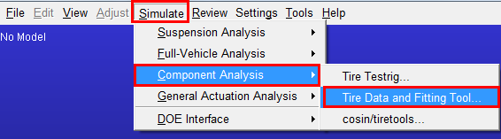
The TDFT can be started from the Adams Car graphical interface by clicking Simulate - Component Analysis - Tire Data and Fitting Tool…
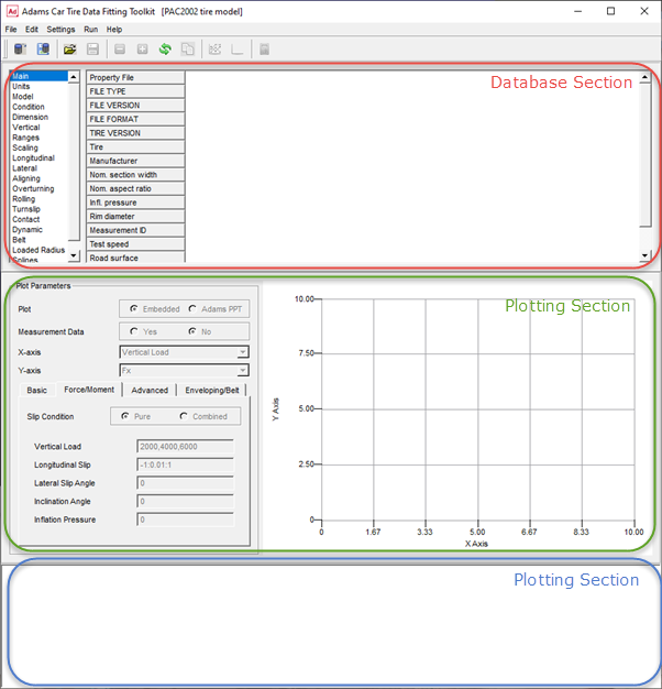
Once the TDFT has started following, the windows shown can be divided in three parts:
■The database section
■The plotting section
■The message window
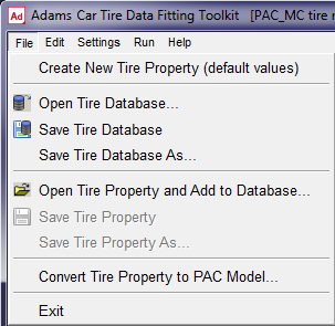
With the Option Create New Tire Property File under File in the menu toolbar, a new tire property file can be opened. Typically this is done when the user wants to calculate PAC2002 or PAC-MC tire model parameters out of tire test data.
The option Open Tire Database… allows you to open a tire data base file (.xml format) that has been saved with Save Tire Database (As)… in a previous session.
With Open Tire Property and Add to Database… any PAC2002 or PAC-MC tire property file can be loaded into the database.
Note that the database can only deal with one type of tire model at the time. When having one PAC2002 tire property loaded, it expects the next tire property file also to be a PAC2002 tire model dataset. If you load another type of property file, it will empty the database and load the new type.
The option Convert Tire Property to Property to PAC Model… offers you to open a non-PAC2002 or non-PAC-MC tire property file, convert this file to PAC2002 or PAC-MC and load the converted parameters to the database. This conversion will work for any Adams Tire model tire property file, except 521-Tire. Note that FTire has a feature in the cosin/tiretools for generating PAC2002 parameters.
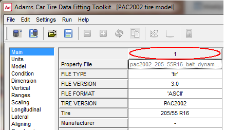
Once having a database with tires a certain tire can be selected by clicking on the column header with the sequence number.
Save Tire Property and Save Tire Property As… will save the selected tire as a tire property file in the common TeimOrbit Format as being used by the Adams Solver.
With the options under Edit item in the menu bar, a tire can be activated or deactivated. Clicking respectively on the Deactivate Tire Property in Database  and the Update Database
  option will remove the selected tire from the database.
and the Update Database option will remove the selected tire from the database.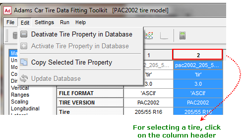
With Copy Select Tire Property, the selected tire will be copied and added to the Database.
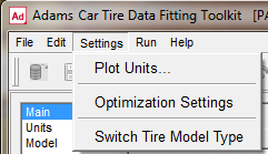
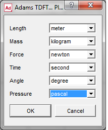
The next menu bar item involves the Settings. The Plot Units can be set as listed in the dialog window listed below:
The second set of Settings, Optimizer Settings is related to the parameter optimizer. You can switch to the other tire model with 'Switch Tire Model Type', that is, from PAC2002 to PAC-MC or backwards. However, this can also be done by importing a tire property file of the other model type.
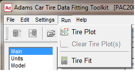
The Run attribute at the menu bar contains the Tire Plot  button for drawing the specified plot as specified in the Plotting section, as well as the Clear Tire Plot(s) button for clearing the graph in the plot section.
button for drawing the specified plot as specified in the Plotting section, as well as the Clear Tire Plot(s) button for clearing the graph in the plot section.Run - Tire Fit will launch the Tire Fit dialog box window from which the user can control the parameter optimization process.
Most of the menu toolbar functions can also be found in the toolbar buttons:

 Open Tire Database
 Save Tire Database
 Open Tire Property and Add to Database
 Save Tire Property
 Deactivate selected Tire
 Activated selected Tire
 Update Database (removes the deactivated tires)
 Copy the selected Tire
 Tire Plot
 Clear Tire Plot(s)
 Tire Fit
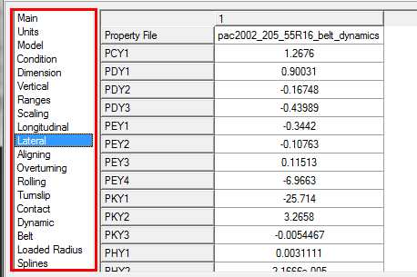
Once a tire has been loaded in the Tire Database, browsing in the tire data selector allows you to display all tire model parameters per section. The user may change each parameters in the database.
Plotting Tire Characteristics
In the plotting section graphs of tire characteristics can be made, either just plots created by the tire model or plots of the tire model against measurement data.
The tire characteristics have been divided in four categories:
■The Basic tire properties. These concern the loaded radius, effective rolling radius, relaxation length and contact patch size as function of vertical load.
■The tire's Force and Moment properties: the steady state tire force response as function of slip, camber and load.
■The Advanced Dynamics properties, determined by the non-rolling longitudinal and lateral stiffness, as well as the parking torque at stand-still.
■The Enveloping and Belt dynamics response when rolling over a cleat with fixed axle height. This option is not applicable for the PAC-MC tire. For this response the TDFT will run simulations of the tire rolling over the specified cleat.
For Creating a plot:
1. Click on File - Open Tire Database or File - Open Tire Property and add to Database
2. Select the tire in the database by clicking on the tires column header:
Note: | Selecting two or more tires will allow you to plot tire characteristics of multiple tires. |
3. Specify the Plot input (Embedded or Adams PPT), the Measurement Data Yes/No selection, X- and Y-axis and click on the tab for the desired tire characteristics:
Embedded or Adams PPT
When selecting Embedded, the TDFT plotting will be used to visualize the graph, otherwise the plot will be generated in the Adams post processor.
Measurement Data
With the Measurement Data radio button the user can select for plotting just the tire model characteristics of the selected tire or compare these model characteristics to the measurement data files as defined in the 'Run - Tire Fit' dialog window. If Measurement Data 'Yes' has been selected no inputs such as Forward Speed, Longitudinal Slip and son on, can be selected because these are defined by in the measurement data conditions.
Basic tire properties
The basic tire properties contain the loaded tire radius, the effective tire radius, the rolling resistance moment, the longitudinal and lateral tire relaxation length, the contact patch length and width, the 'advanced longitudinal relaxation length' and the 'advanced lateral relaxation length'. These can be visualized as function of vertical load, longitudinal slip and lateral slip angle. The user can specify the conditions for the graph in terms of forward speed, vertical load, longitudinal slip (-1 to 1), the slip angle, inclination angle and inflation pressure. When inflation pressure is set to 0, the nominal tire inflation pressure (IP_NOM) will be used.
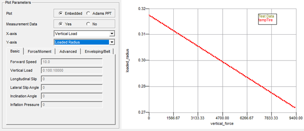
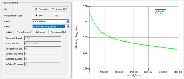
Example of the effective rolling radius and loaded radius as function of the vertical load:
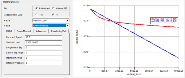
Note: | For the chosen X-axis parameter, one needs to define a sweep with the minimum value, the step size and the maximum value, separated by a colon. min value : increment : max value 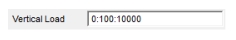 |
The tire (standard) longitudinal and lateral relaxation is calculated with PAC2002 or PAC-MC with the linear transient model (USE_MODE = 11 - 14), while the advanced longitudinal and lateral relaxation is calculated with the PAC2002 or PAC-MC model in advanced transient mode (USE_MODE = 21-25). For calculating the (standard) longitudinal and lateral the formulae (121) and (122) are used as listed in the section 'Linear transient model'.
In order to calculate the advanced relaxation length (see Transient Behavior in PAC2002) the Tire Data Fitting Tool will start tire testrig simulations in the background in which the tire is excited with a step slip input. The tire's step response is used to calculate the relaxation.
In the figure below an example plot of the lateral relaxation as function of the slip angle step as a constant load is shown:
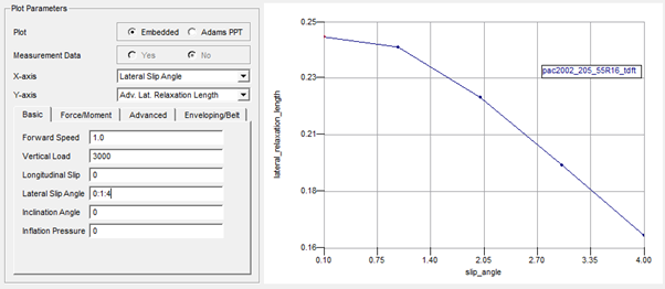
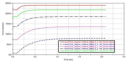
The simulations ran by the TDFT in the background for generating this plot will show following lateral force response on the slip angle step excitation (as function of time):
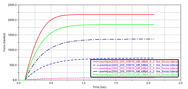
The lateral force response data is used to calculate the lateral relaxation length assuming that the tire dynamics response system to be a first order system: the relaxation length is the distance travelled by the tire for reaching 63% of the final force value. Note that this direct simulation result (lateral force as function of time) cannot be plotted within the TDFT.
Note: | The forward velocity specified for this test should be low, preferably below 5 m/s. |
The simulation run for deriving the relaxation length values can be run in 'parallel' mode, the number of maximum parallel simulation can be defined in the Optimization Settings dialog box.
Force and Moment properties
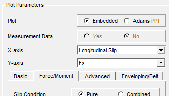
The force and moment properties can be plotted in pure slip conditions or combined slip:
■Pure slip conditions means either:
♦A free rolling tire subject to lateral slip (slip angle) and camber
♦A tire rolling straight (no lateral slip) subject to longitudinal slip (by brake or driving torque)
■Combined slip means a combination of longitudinal and lateral slip.
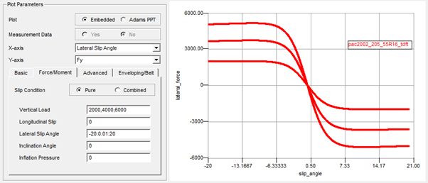
Next to the Slip Condition radio button, the user needs to specify the Vertical Load, Longitudinal Slip, Lateral Slip Angle, Inclination Angle and Inflation Pressure.
One of these input boxes needs to specify the sweep variable: the variable that is varied over a specific range, with the minimum value, maximum value and the increment, to be defined with a colon separator:
min value : increment : max value
The other input boxes should specify at least one value. If more than one condition is specified, separated by a comma, for each condition a curve will be plotted.
value1 , value 2, value 3
Advanced Dynamics properties (not applicable to PAC-MC)
When having the tire use mode > 20, the advanced transient model is used, which allows a more accurate transient dynamics modeling over the linear transient model (10 < use mode < 14). With the advanced dynamics, also the non-rolling longitudinal, lateral and yawing (parking torque) behavior of the tire is considered.
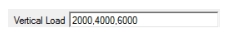
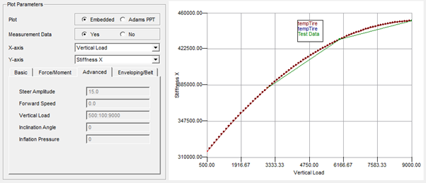
When clicking on the Advanced tab, the longitudinal (Stiffness X) and lateral (Stiffness Y) stiffness for the non-rolling as function of the vertical load can be plotted:
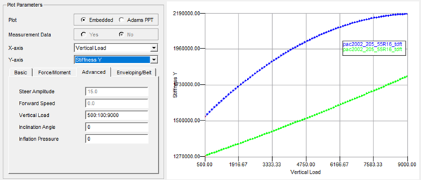
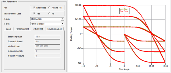
For the torque response of the tire when rotating about the vertical z-axis the so-called parking torque can be plotted:
In this case the tire is simulated in a tire test rig model applying a sinusoidal steer angle with the specified ‘Steer Amplitude’ and the ‘Vertical Load’ at a zero forward speed.
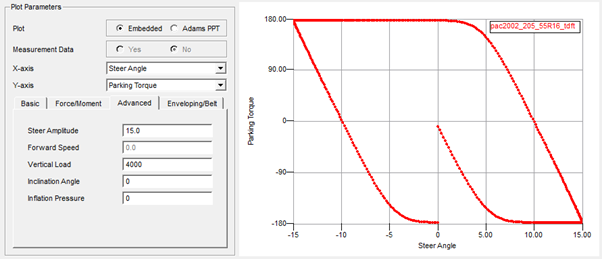
Enveloping and Belt Dynamics properties (not applicable to PAC-MC)
This section visualizes the tire force response of a tire rolling over a cleat obstacle at fixed axles height.
These tire cleat tests are considered to be best method for analyzing the tire's enveloping and belt dynamics properties. The Enveloping forces are estimated with a cleat test under following conditions:
■Forward speed < 2 m/s (for avoiding inertia effects)
■Free rolling tire
■The cleat is perpendicular to the wheel plane
■The cleat height and length are in the range of 5% of the tire radius, max 10%.
For tire Belt dynamics the cleat tests are similar but:
■Forward speed is larger (> 2m/s), the cleat will excite the tire belt eigen modes.
■The angle of the cleat with respect to the wheel plane can be varied.
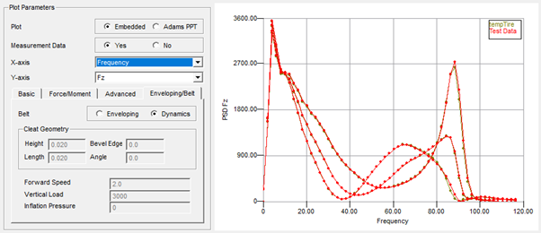
The forces (Fx, Fy, Fz) plotted in the graphs are the forces of the tire/wheel on the wheel axis (hub forces), they can be plotted as function of time, distance or frequency. For the frequency - force plot the force PSD is calculated using an FFT transformation.
Enveloping / Dynamics (not applicable to PAC-MC)
When clicking on the Enveloping button, tire belt mass effects are neglected (PAC2002 is running in use mode 14 with the 3D Enveloping Contact).
Note: | If a Forward Speed is specified larger than 2 m/s, a warning message will be generated: Warning: For forward speed larger than 2 m/s tire dynamics will play an important role. |
Cleat Geometry
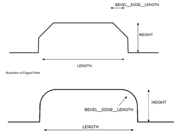
The cleat geometry is defined in line with the 'Plank' obstacle in 2D Road and 3D Spline Road:
■A negative Bevel Edge value will create the lower obstacle with rounded corners.
■A Cleat Angle of 0 degree defines a cleat perpendicular to the wheel plane.
■At Inflation Pressure input of zero the nominal inflation pressure will be taken (IP_NOM).
When creating Enveloping or Belt dynamics plots, clicking on the Tire Plot button  will start the tire testrig simulation(s) required to calculate the tire hub force response, following message will appear in the message window:
will start the tire testrig simulation(s) required to calculate the tire hub force response, following message will appear in the message window:Please wait, simulating cleat tests…
After the simulation(s) have finished the plot will be displayed, for example:
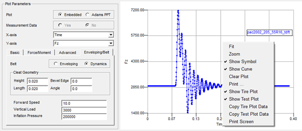
Note: | A right mouse click on the plot area will show you the menu for zooming, changing the line properties, symbol size and printing. |
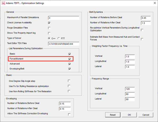
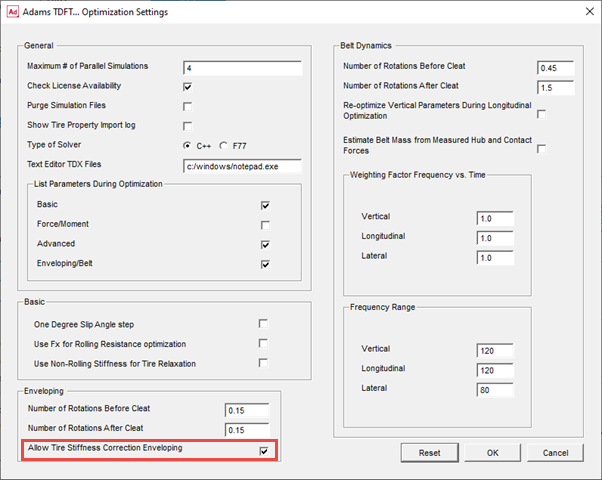
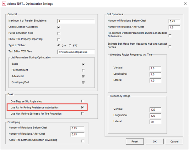
More detailed options for the cleat simulations can be defined in the Optimization Settings dialog box window, click on Settings - Optimization Settings.
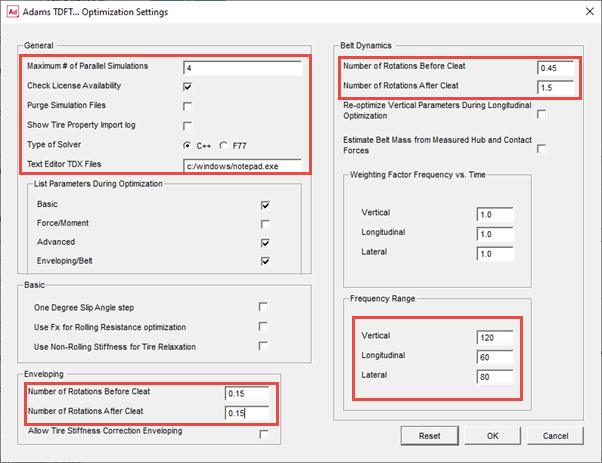
Though most of the settings in this dialog are valid for the optimizer that calculates the Enveloping and Belt Dynamics parameters, some of them are used for the plotting as well, indicated with the red boxes.
Maximum Number of Parallel Simulations
The tire rolling over cleat simulations can be performed parallel, in case more than one is required. Here the maximum number of parallel simulations can be defined.
Check License Availability
The license availability can be checked when the user is closing this window, this to avoid problems when multiple parallel simulations are run. When clicking Ok, following will appear in the message window:
Checking if number of requested licenses is available, please wait...
Succes: sufficient licenses available for 5 parallel simulations
Purge Simulation Files
For removing all (intermediate) files generated for the tire cleat simulations and by the Adams Solver.
Show Tire Property Import Log
When clicking on the 'Import Tire Properties' button in the 'Run - Tire Fit' view, the common tire properties found in the TYDEX files will be imported into the database. The log file ('TDFT_tire_property_import.log') explaining the details about this process will be shown to the user when this checkbox is set.
Type of Solver
Let's you select the type of solver to be used for plotting and optimization activities that require tire testrig simulations.
Text Editor TDX Files
Here one can specify the editor to be used for editing the >TDX files in the Fit View TDX file matrix table.
Number of Rotations Before Cleat
For specifying the number of rotations (usually a part of a full rotation) that the tire should have rotated before hitting the cleat. Different values can be specified for Enveloping and Belt Dynamics.
Number of Rotations After Cleat
For specifying the number of rotations (usually a part of a full rotation) that the tire should rotate after hitting the cleat. Different values can be specified for Enveloping and Belt Dynamics.
Frequency Range Vertical Force PSD
Specifies the max frequency range for the vertical force PSD. Note that this range is not only for the plotting but is also used for the Belt Dynamics parameter optimizer. For the optimizer, the range should cover the vertical force related eigen frequencies of the belt.
Frequency Range Longitudinal Force PSD
Specifies the max frequency range for the longitudinal force PSD. Note that this range is not only for the plotting but is also used for the Belt Dynamics parameter optimizer. For the optimizer, the range should cover the longitudinal force related eigen frequencies of the belt.
Frequency Range Lateral Force PSD
Specifies the max frequency range for the lateral force PSD. Note that this range is not only for the plotting but is also used for the Belt Dynamics parameter optimizer. For the optimizer, the range should cover the lateral force related eigen frequencies of the belt.
Reset
When clicking the Reset button, the TDFT default settings will be taken.
Calculating the PAC2002 or PAC-MC tire model parameters out of tire measurement data
When having the appropriate tire measurement data, the PAC2002 or PAC-MC tire model parameters can be calculated using the TDFT optimizers. First the fitting process, starting with a new tire and calculating all tire model parameters, will be explained, then the requirements tire on the test data and tire data file format will be described.
Fitting process from begin to end
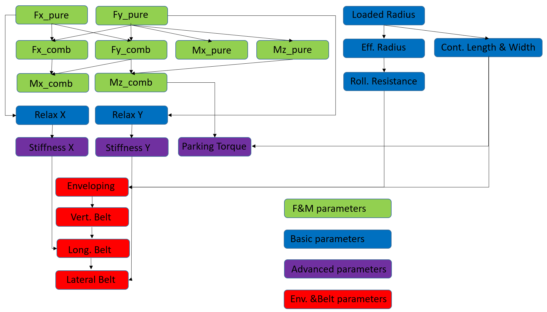
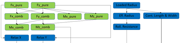
The TDFT controls four optimizers each for the following groups of test data:
■Force and Moment properties
■Basic tire properties
■Advanced Dynamics Properties
■Enveloping and Belt Dynamics properties (not applicable for PAC-MC)
Each group in itself contains different tire properties, and requires following related tire test data:
■Force and Moment properties:
■Pure slip condition data:
♦Lateral force (Fy), Overturning Moment (Mx), Aligning Moment (Mz) measured during a change of slip angle and camber on a free rolling tire at certain vertical loads or
♦Longitudinal force (Fx) measured during a change of longitudinal slip and camber on a straight running tire at certain vertical loads.
■Combined slip condition data:
♦Measured forces and moments (Fx, Fy, Fz, Mx, Mz) on a tire under combined cornering and longitudinal slip conditions.
■Basic tire properties
■Loaded tire radius as function load, forward speed, lateral and longitudinal force and inflation pressure
■Effective tire rolling radius as function of load and speed
■Rolling resistance as a function of load
■Tire contact patch length and width as function of load
■Tire relaxation length as function of load, or tire lateral of longitudinal stiffness (non-rolling) as function of load.
■Optional: If more accuracy is required for transient response, but no belt dynamics data is available, one can consider to use the advanced (non-linear) transient of PAC2002 or PAC-MC. In that case the USE_MODE should be set in the range of 21 until 25, see section 'Non linear transient model' of PAC2002 or section 'Non linear transient model' of PAC-MC.
■Advanced Dynamics properties
■Longitudinal stiffness of the non-rolling tire
■Lateral stiffness of the non-rolling tire
■Yaw stiffness and peak torque on the non-rolling tire (Parking torque)
■Enveloping and Belt Dynamics properties (not applicable for PAC-MC)
■Vertical tire hub force measured when rolling over a cleat (perpendicular to the wheel plane) at fixed axle height at low speed (< 2 m/s).
■Vertical and longitudinal tire hub force measured when rolling over a cleat (perpendicular to the wheel plane) at fixed axle height at moderate speeds (> 2 m/s).
■Lateral tire hub force measured when rolling over a cleat (having an angle close to 45 deg) at fixed axle height at moderate speeds (> 2 m/s).
The fit process exists of different steps in a certain sequence:
The fit process starts with creating a new tire in the database and selecting the appropriate tire measurement data:
1. Click on File - Create New Tire Property
2. Select the type of tire model that you want to apply:
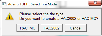
3. Select the tire (at the top of the column) and click on Run - Tire Fit
4. Click on the Add measurements by file or directory button  .
.
.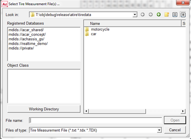
5. Select all TYDEX (.tdx) files [1] in the motorcycle or car directory, depending on the type of tire model that you selected. In this example the car tire data files are selected.
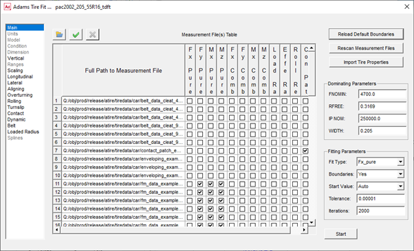
The TDFT will scan all files and detect the kind of data that is available in each file, so that each file can be used for the right optimization process. This checkmark matrix will also allow the user to de-select a certain file for a certain optimization process.
Note: | A double click on the measurement file name will open the file with an ASCII editor. The editor can be specified in the 'Optimization Settings' dialog. |
6. The first step when the tire data files have been imported is to transfer the tire information (tire size, diameter and so on) available in the TYDEX (.tdx) files [1] into the database by clicking the button Import Tire Properties. The message window will list the info transferred:
Importing NOMWIDTH, value: 0.205
Importing ASPRATIO, value: 0.55
Importing RIMDIAME, value: 0.4064
Importing RIMWIDTH, value: 0.1651
Importing TYREMASS, value: 9.3
Importing TRCKCOND, value: dry
Importing NOMPRES, value: 250000
Importing FZ_NOM, value: 4700, FZMIN set to: 23.5, FZMAX set to: 9400
Importing RFREE, value: 0.3169
7. Next is to check the Dominating Parameters: these parameters must have the right value before starting the optimizer with the first optimization process:
FNOMIN | is the nominal load of the tire (Fz0), this should be a value close to the nominal tire load under the vehicle. |
RFREE | is the unloaded tire radius |
IP_NOM | is the nominal inflation pressure of the tire |
WIDTH | is the tire width |
TYREMASS | Is the mass of the tire (important for belt dynamics only) |
Note: | When changing one of the Domination parameters, the full tire optimization has to be repeated! |
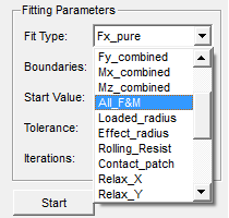
8. Now, the first fitting process can be started with calculating the parameters for the tire's Force & Moment properties. The F&M fit process can be done step by step or in one step all F&M parameters.
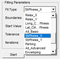
By clicking at the Fit Type combo box, one can click on the appropriate fit process.
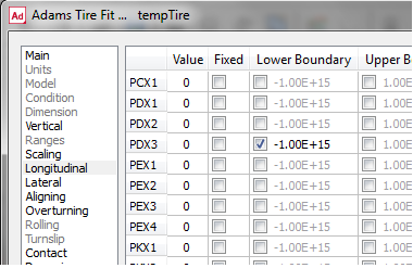
Boundaries
The optimizer can apply minimum and maximum allowable values for each parameter. When clicking on the left tire parameter section browser, the Fit View will display the value, starting value, and boundaries for each parameter:
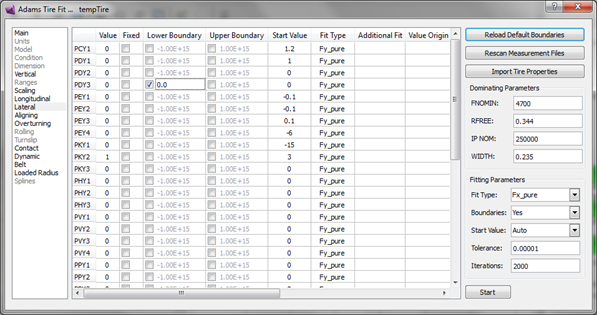
When Boundaries is set to 'No', none of the boundaries is applied. If Boundaries is set to 'Yes', the boundaries are applied that have their checkbox clicked (see example with PDX3). For editing a boundary, use right mouse click.
Start Value
Start Value has three options for selecting the starting value of each parameter for starting the optimization process with:
♦Auto: appropriate values are estimated from the measurement data
♦Start Value: the value in the 'Start Value' column is taken as starting value. The user can adjust this value.
♦Value: the value in the 'Value' column is taken. The parameter value in the 'Value' column is identical to the value in the Tire Database.
With clicking the checkbox in the Fixed column, a parameter can be discarded from the fitting process. In that case the value in the 'Value' column will be taken as fixed value and will not be optimized.
The Tolerance value is used by the optimization process as the criterion to stop the fitting process, while the Iterations number defines the maximum allowed number of iterations. When reaching the maximum, the optimizer will abort the optimization process.
Fit Type
In the column Fit Type, the type of fit is specified in which the corresponding parameter is calculated during an optimization process. In case of special needs, the user can change the Fit Type. Changes will be saved when the tire is saved in a database (File - Save Tire Database).
Additional Fit
In this column possible use of other Fit Types are listed, for example. If LMUX is not fixed, it will be added to the optimization process for 'Fx_combined'. Note: Changes in this column will have no effect on the selection of parameters by the optimizer.
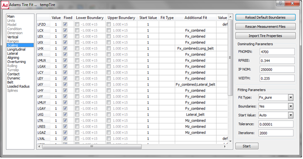
Value Origin
The Value Origin supplies information about parameters that are not calculated by the optimization.
Comment
In the 'comment' column a brief explanation about the parameters is listed.
When clicking on Start, the fit process for Fx_Pure will start, and the message window will list:
Fittype: Fx_Pure Number of points: 2400
Standard deviation of the residuals: 0.000006 [N]
The standard deviation is the average difference in between the measurement data points and the tire model representation according to:
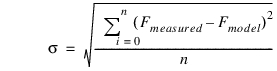
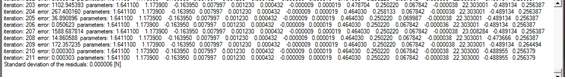
If interested, one can have the parameter variations printed during the fitting process when changing the 'List Parameters During Optimization' setting in the Optimization Settings dialog box.
In addition to the information printed in the message window, a log file will be created and stored in the working directory, with the name: <tire_name>_<Fit_Type>.log.
The log file will report the fitting process in detail (tire test data file used, starting values, boundaries set, parameter variations per iteration step and so on.).
9. After a fit has been performed the agreement in between the data and the model representation can be visualized in the plot window.
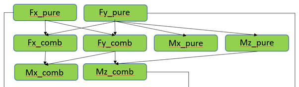
Before continuing with the plotting, please make sure all fits for the F&M parameters have been performed. To do so, click on Fit Type 'All_F&M':
all Force and Moment parameters will be calculated in the right sequence.
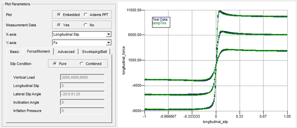
For the plotting, close the Tire Fit window, and click on the Force/Moment tab in the plotting section.
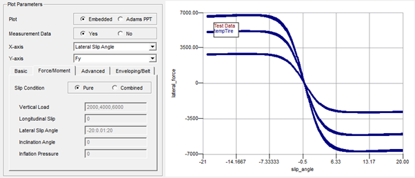
Click on Plot Embedded, Measurement Data - Yes, slip Condition Pure and click on the Run - Tire Plot button.
A comparison will be showed in between the model representation and the test data for the pure longitudinal slip data. Because the example data is 'virtual test data' and has been derived using the PAC2002 or PAC-MC model, the differences are almost not visible.
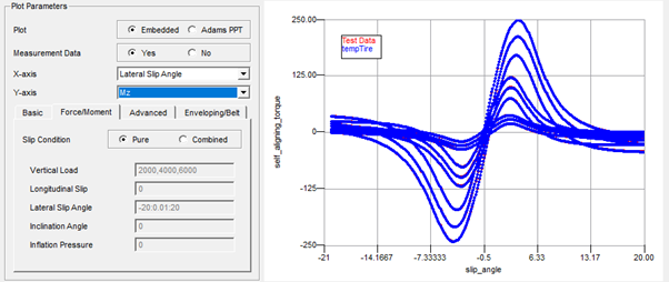
Similar a plot can be made for the pure cornering data:
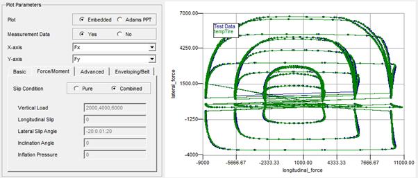
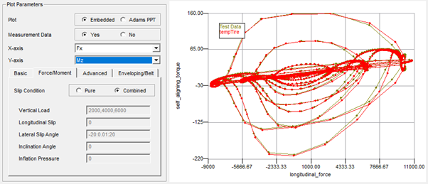
And the combined slip data:
10. Next step is the calculation of the Basic property parameters, click on Run - Tire Fit for the Tire Fit View. Again several Fit Types exist for the Basic properties:
When selecting the Fit Type, the optimization can be done step by step or all in one sequence (All_Basic).
After all steps have been executed, returning to the plot section, following plots can be made comparing the fit with the data:
Loaded Radius:
Effective Rolling Radius:
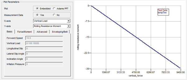
Rolling Resistance Moment
Longitudinal Relaxation Length:
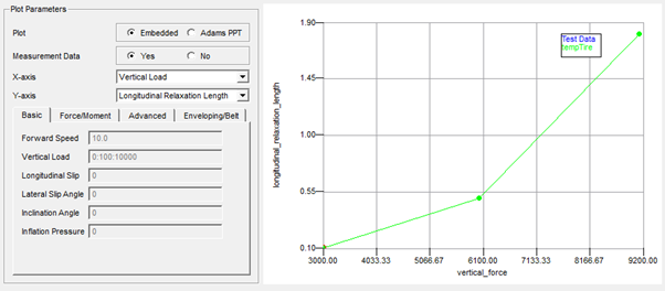
Note that just 3 data points are available in the data. One could verify the interpolation of the tire model in between these points by adding another plot (do not Clear Tire Plot) with the Measurement Data radio button on 'No':
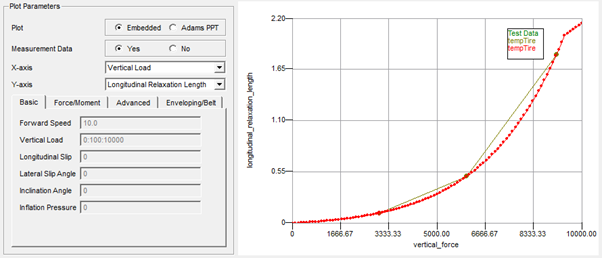
Note: | The relaxation length is limited above the Fz MAX range value. |
Lateral Relaxation Length:
Similar the plot for the Lateral Relaxation Length will show following result:
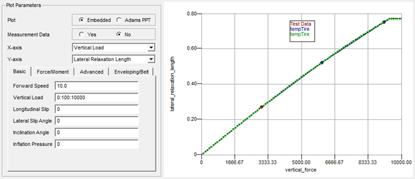
Note: | The relaxation length is limited above the Fz MAX range value. |
Contact Patch Length:
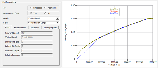
Note: | The contact patch length is limited above the Fz MAX range value. |
Contact Patch Width:
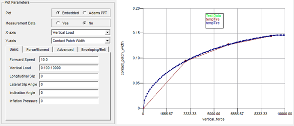
Note: | The contact patch width is limited above the Fz MAX range value. |
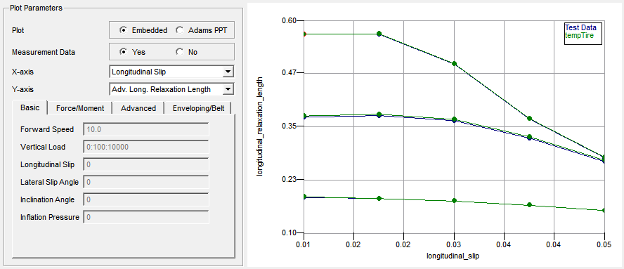
Advanced Longitudinal Relaxation Length:
As an option, if high accuracy of the transient tire response is required one can choose to fit also tire relaxation data as function of load and slip. When the tire model is used in the advanced (non-linear) transient mode (USE_MODE = 21-25), the relaxation load and slip dependency will be used, see section 'Non linear transient model' of PAC2002 or the section 'Non linear transient model' of PAC-MC.
The example files contain such data. Note that fitting these data requires tire testrig simulation to verify the tire model response to a step slip input, and thus will more time than the other basic parameter optimization processes.W
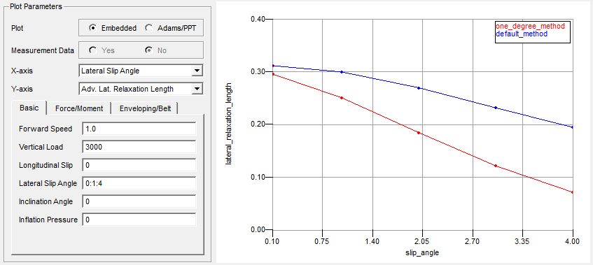
Advanced Lateral Relaxation Length:
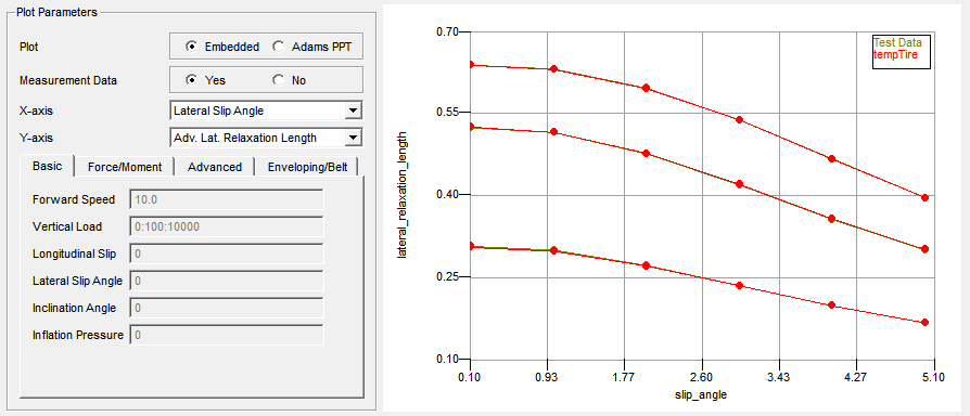
In general there are two methods for calculating the lateral relaxation (See Transient Behavior in PAC2002) out of slip step input data:
a. In the default method the step size of the slip varies: at the start of the simulation the side slip is zero, the step size depends on the value of slip interested. This would result in simulations result that will show following side force response as function of time:
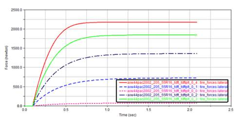
Note: | These simulation (lateral force as function of time) results cannot be accessed or plotted in the TDFT. These results are derived from simulations with a tire testrig in the background and are processed towards relaxation length values directly, and just these relaxation values can be plotted in the TDFT. |
b. In the 'Optimization Settings' dialog window another method can be chosen, see below:
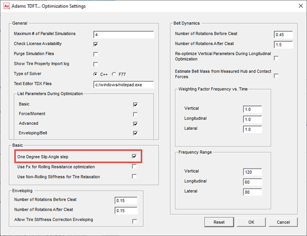
In this method the slip angle step is always one degree slip and starts at the value of slip:
Note that the relaxation values will differ considerably, in particular for larger values of side slip:
Note: | This Advanced Longitudinal and Lateral Relaxation Length is using relaxation test data. The same parameters can also be determined with longitudinal and lateral stiffness data in the Advanced Dynamics step. |
Fx for Rolling Resistance optimization
When checking the box for 'Use Fx for Rolling Resistance optimization' the measured longitudinal force Fx will be used for calculating the rolling resistance parameters (Qsy parameters) instead of the rolling resistance torque (My).
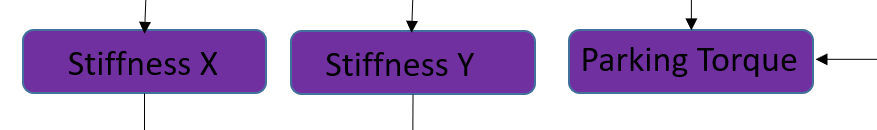
11. The third group of parameters are the Advanced Transient parameters (not applicable for PAC-MC):
The tire non-rolling stiffness in longitudinal and lateral direction and the yawing properties (stiffness and peak moment, the so-called parking torque). The related fit steps are Stiffness X, Stiffness Y and Parking Torque.
The tire non-rolling stiffness in longitudinal and lateral direction and the yawing properties (stiffness and peak moment, the so-called parking torque). The related fit steps are Stiffness X, Stiffness Y and Parking Torque.
Longitudinal Stiffness of the non-rolling tire
The longitudinal stiffness of the tire should be measured as function of the vertical load, resulting in following plot:
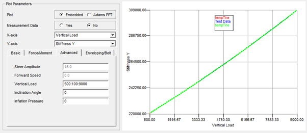
Lateral Stiffness of the non-rolling tire
Similarly, the lateral stiffness is a function of vertical load:
Parking Torque (yaw properties)
The torque due to the width of the non-rolling tire when rotating around the z-axis is characterized by a applying a sine steer angle in a tire testrig. When plotting the (parking) torque as a function of the steer angle for different vertical loads, following picture is shown:
12. The fourth group of parameters are the parameters for Enveloping and Belt Dynamics. (not applicable for PAC-MC)
The Enveloping parameters concern the parameters for the ellipsoid cams of the Enveloping filter. These parameters are determined by minimizing the differences in vertical force calculated by the model and the test data of the tire when running over a cleat at low speed at fixed axle height.
For each test data file a simulation has to be performed in each iteration cycle of the optimizer. To reduce time, the number of parallel simulations as specified in the Optimization Settings is crucial.
After starting the Optimizer with Fit Type Enveloping, the optimizer will submit a tire test rig model to Adams Solver and run the model with the velocities, vertical load settings and cleat geometry as specified in the TYDEX (.tdx) files. Once the optimizer has finished the process, and the parameters are loaded into the Tire Database, plots can be made in the plotting section.
When creating the plots, again a simulation with the tire test rig model will be executed in order to get the tire model response (with the parameters stored in the Tire Database) and plot this against the test data:
Note: | For enveloping the vertical tire stiffness is quite important. In case the enveloping tests have been performed on a curved surface (drum) and the loaded radius test on a flat surface (or vice versa) problems can occur to get accurate enveloping results. If such surface curvature differences exist or if there is any reason to doubt whether the vertical tire stiffness (loaded radius) data is valid for the enveloping test, the Optimization Settings offers a switch to allow the optimizer adjusting the vertical tire stiffness during the Enveloping optimization, see below: |
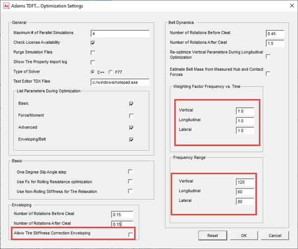
13. Optimizing the Belt Dynamics parameters is primarily focused on getting the stiffness and damping rates of the belt with respect to the rim so that the lowest eigen frequencies can be covered accurately. Therefore the optimizer is comparing test data not only in time domain, but also in frequency domain. The importance of the error in frequency domain related to the error in time domain for the optimizer can be set by the 'Weighting Factor Frequency vs. Time' factors in the Optimization Settings dialog box window. By default just the frequency domain error (factor = 1) is used, see above.
A factor 0 would mean that just the time domain error would be applied.
In addition the applied frequency range can be specified. This range should cover the lowest eigen frequency of the tire belt.
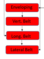
The Belt Dynamics optimization process is applied in three steps:
♦Vertical belt dynamics (cleat perpendicular to wheel plane)
♦Longitudinal belt dynamics (cleat perpendicular to wheel plane, same as above)
♦Lateral belt dynamics (cleat has an angle with the wheel plane close to 45 deg)
The option 'Estimate Belt Mass from Measured Hub and Contact Forces', will calculate the belt mass from the differences in the vertical hub and contact forces. In that case the FZW and FZC (or FZH) signals need to be provided in the .tdx files.
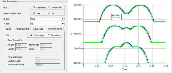
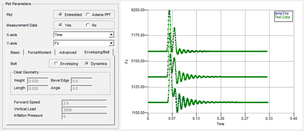
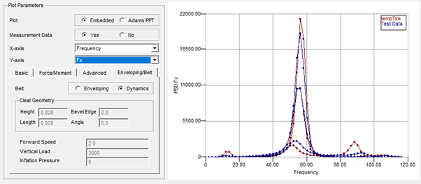
After the optimization process on the vertical belt dynamics has finished following graphical comparisons can be made:
A plot in time domain would show following:
Note: | If interested in a plot of a specified tire test data file, one could adjust the file selection in the test data checkbox matrix in the Tire Fit View. |
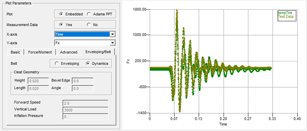
The optimization on the longitudinal tire dynamics (Fit Type = Long_Belt) can be visualized with following graphs. Note that the parameters for Vertical Belt Dynamics are re-calculated by default, however this could be switched off in the Optimization Settings dialog box window.
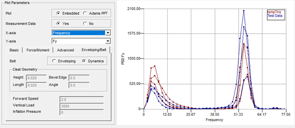
The optimization of the lateral belt dynamics delivers following results:

Converting a non-PAC2002 or non-PAC-MC tire property file
The TDFT offers a feature to convert non-PAC2002 tire property files of any other tire model that runs in Adams and is compliant with the Standard Tire Interface or Cosin Tire Interface. In addition, the tire property file needs be formatted in Teim Orbit.
The conversion process can be started by clicking at File - Tire Property to PAC2002 (or PAC-MC) model. Following dialog box window will be shown:
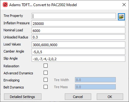
In addition to the selection of the tire property file, the user can specify the working area of the tire:
■The nominal load should be close to the static load on the tire under the vehicle for having best accuracy.
■The unloaded tire radius will be derived from the selected tire property file, if not correct it can be corrected here.
■The load values should cover the range of use of the tire under the vehicle, a minimum of three loads is advised.
■Similar the camber angles (for pure cornering) and slip angles (for combined slip) should cover the range of used of the tire. For the camber a minimum number of three load settings is preferred, while the number of slip angles should be at least 6.
■When the tire property file to be converted supports transient tire behavior, one can choose for having the first order transient tire behavior incorporated in the PAC2002 or PAC-MC by checking the Relaxation checkbox.
■The advanced transient properties (stiffness for the non-rolling tire and parking torque) can be converted when the Advanced Dynamics checkbox is marked.
■Similar if the original tire model can describe the tire model enveloping or belt dynamics effects, the Enveloping and Belt Dynamics checkboxes can be checked.
If the tire property file is a property file from one of the Adams Tire model (not a 'USER' tire model), the irrelevant options will be disabled.
The 'Detailed Settings' button will launch a dialog that allows you to specify the conversion settings in more detail:
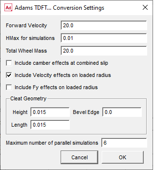
The Forward Velocity resembles the forward speed used for the tire in the tire test rig simulations (except for the enveloping cleat test and the tests for the relaxation effects). If the original tire model has solver setting requirements in terms of a maximum HMAX step size, this can be specified here. Further the default Total Wheel Mass (rim and tire) as used in the simulations is listed here and can be changed, in particular for the Belt Dynamics effects this is important.
If the 'Include camber effects at combined slip' checkbox is checked, the combined slip simulation for the Force and Moment properties will also be performed at the (other) non-zero camber values specified in the main conversion dialog window.
The 'Include Velocity effects on loaded radius' will add virtual test data to identify the tire radius growth and stiffness change as function of forward speed.
The 'Include Fy effect on loaded radius' checkbox allows you to add loaded radius simulations with the slip angle values so that possible lateral force effects on the tire vertical stiffness will be identified.
Though the default geometry settings used for the cleat in the Enveloping and Belt Dynamics optimization can be used in most of the cases (the 3D Enveloping is valid for cleats not larger than half the side wall height), one can also adjust the cleat geometry used during the conversion.
For speeding up the conversion process the Maximum number of parallel simulations can be specified (depending on number of CPU's and Adams solver licenses).
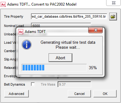
After clicking 'Ok', the conversion process starts with generating virtual tire measurement data by running tire test rig simulations for different conditions (depending on the capabilities of the model):
■longitudinal slip sweeps in straight line, for the pure longitudinal slip Force and Moment (F&M) properties, at the load values specified in the upper conversion dialog.
■lateral slip sweeps (slip angle), for the pure lateral slip F&M properties, at the loads and camber settings specified in the conversion dialog
■longitudinal slip sweeps with a fixed slip angle for the combined slip F&M properties, at the loads and slip angle settings specified in the conversion dialog. If the 'Include camber effect at combined slip' checkbox is selected in the Advanced dialog window, also longitudinal slip tests will be performed with the camber settings specified, otherwise just zero camber will be applied.
■a straight line free rolling test of the tire with increasing load for getting data on the tire loaded radius, tire effective rolling radius and the rolling resistance (basic tire properties). If the 'Include Fy effects on loaded radius' checkbox is selected, the loaded radius tests will be repeated for the slip angle values as specified in the conversion dialog window.
■if the Relaxation or Belt Dynamics checkbox is selected, tests for getting the longitudinal and lateral (non-rolling) stiffness of the tire for the specified loads are run. The stiffness data allows to calculate the longitudinal and lateral relaxation length of the tire.
■if the Enveloping checkbox is selected, cleat tests (tire rolling over a cleat a fixed axle height) at low speed (1 m/s) are run to get the data for deriving the enveloping parameters. For each specified load one cleat test simulation is done. The cleat is perpendicular to the wheel plane.
■if the Belt Dynamics checkbox is selected, cleat tests at the specified forward velocity and specified loads are executed, with a cleat perpendicular to the wheel plane (vertical and longitudinal belt dynamics) and a cleat under 45 deg angle with the wheel plane (lateral belt dynamics).
Once the simulations are finished the relevant data for the parameter calculation is extracted from the simulation results and converted into TYDEX formatted files, and imported into the Fit View window, the parameter optimization will start:
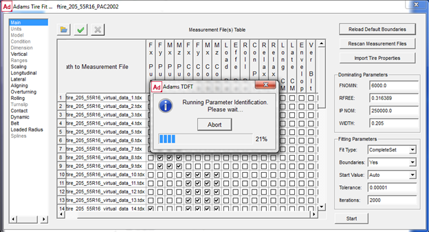
If the optimization has finished, the quality of the parameter optimization can be checked with the optimization .log files and the plotter by comparing the virtual test data with the PAC2002 representation as specified in the section Calculating the PAC2002 or PAC-MC tire model parameters out of tire measurement data.
Converting a tire property file with inflation pressure effects
In general, the inflation pressure is not a ‘dynamic’ input to a tire model (like load, or slip angle), but just an initial condition that often is defined in the tire property file. For taking into account the effect of inflation pressure, one can select several tire property files, each valid for one inflation pressure:
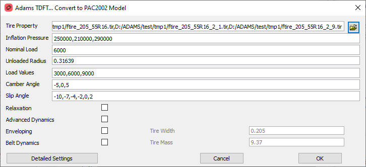
In addition, one needs to fill in the inflation pressure values, so that the optimizer can take into account the appropriate inflation pressure value for each property file. Three inflation pressure settings will be sufficient to calculate all relevant inflation pressure parameters.
Calculating PAC2002 or PAC-MC parameters: Tips and Tricks
Force and Moment data inconsistency in between pure and combined slip conditions.
The PAC tire model calculates the combined slip forces based on the forces calculated for the pure slip conditions. In other words, the forces measured in pure slip conditions should be consistent with the force measured in the combined slip case, otherwise the optimizer will run into trouble.
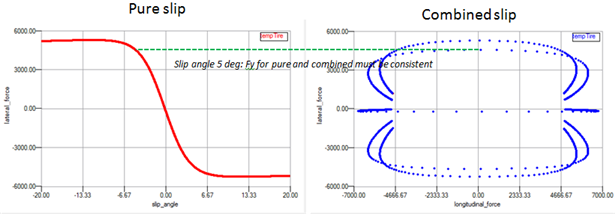
If it appears that the data in between the pure and combined slip is not consistent, the user may add scaling factors (for friction and/or stiffness) to the combined slip fit types, potential candidates are LKX, LMUX, LKY and LMUY.
One can add these scaling factors to the fit process for combined slip, when removing the  sign in corresponding checkbox in the 'Fixed' column before starting the fit.
sign in corresponding checkbox in the 'Fixed' column before starting the fit.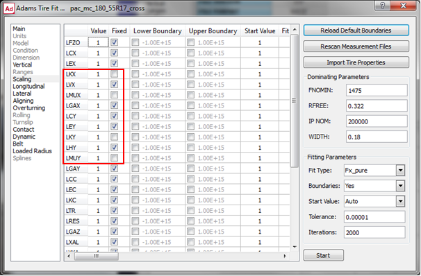
Effect of drum curvature on Enveloping
The vertical tire stiffness plays an important role for the enveloping properties of a tire.
In case the enveloping test have been performed on a curved surface (drum) and the loaded radius test on a flat surface (or vice versa) problems can occur to get accurate enveloping results. If such surface curvature differences exist or if there is any reason to doubt whether the vertical tire stiffness (loaded radius) data is valid for the enveloping test, the Optimization Settings offers a switch to allow the optimizer adjusting the vertical tire stiffness during the Enveloping optimization, see below:
After finalizing the Belt Dynamics fitting, one could put back the loaded radius properties for a flat surface by re-fitting the loaded radius properties again.
Accurate Rolling Resistance
For getting the rolling resistance parameters as part of the 'Basic Tire properties', the rolling resistance torque in the tire-road contact point is required. However, this may be difficult to measure, because measuring in the contact point itself is not feasible.
Common practice would be to measure the moment in the hub (which is zero for a free rolling tire) and transfer the resistance torque to the contact point using the longitudinal force, the vertical force and tire deflection.
In order to avoid this step, the TDFT offers an option to calculate the rolling resistance parameters based on the measured longitudinal force: assuming that the resistance moment at the hub is zero, and knowing the deflection of the tire (using the parameters in the loaded radius fitting), the rolling resistance parameters can be calculated in an alternative way:
My(contact point) = 
In which  is the tire deflection, R0 the unloaded tire radius and Fx the (measured) longitudinal tire force.
is the tire deflection, R0 the unloaded tire radius and Fx the (measured) longitudinal tire force. In the 'Optimization Settings' one can select the type of optimization for the rolling resistance:
This means that the longitudinal tire force and longitudinal slip must be part of the TYDEX file provided to the TDFT for the rolling resistance optimization, see a snippet of an example TYDEX file below:
**CONSTANTS
TYREMASS Tyre mass kg 9.37
NOMWIDTH nominal section width of tire m 0.205
INFLPRES infl. pressure (not defined) bar 0.0
LONGVEL Longitudinal velocity m/s 20
SLIPANGL Nominal slip angle rad 0
INCLANGL Nominal inclination angle rad 0.0
**MEASURCHANNELS
LONGSLIP longitudinal slip %
FX longitudinal N
FYW lateral force N
FZW vertical load N
MYW rolling resistance moment Nmm
DSTGRWHC Dist.ground - wheel centre mm
KROLRAD Kinematic rolling radius mm
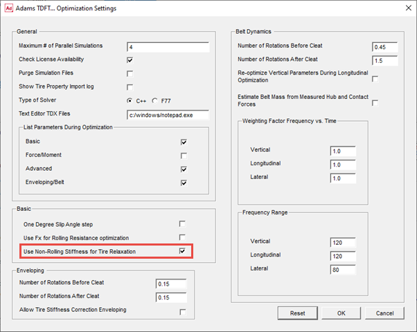
Relaxation and non-rolling Stiffness
For linear transient properties of the PAC2002 and PAC-MC tire model, tire relaxation data as function of load is required. With this data the coefficients for the relaxation in x- and y-direction can be calculated. Relaxation can be determined using a step slip input or a sine wave variation of the slip. An alternative for estimating the relaxation is measuring the non-rolling longitudinal and lateral stiffness of the tire (see also Tire Data Format, RELAX_X and RELAX_Y). In that case the checkbox for ‘Use Non-Rolling Stiffness for Tire Relaxation’ needs to be checked. Then the TYDEX keywords CXTYRE and CYTYRE will be recognized as valid input for tire relaxation input, otherwise RLXLENX and RLXLENY.
Note: | This is valid for the linear transient relaxation (use mode 14) only. When also Advanced Dynamics tire properties are derived, the longitudinal and lateral stiffness of the tire is used for the Advanced transient, and relaxation derived by step or wave slip excitation should be used. |
Required Tire Test Data
The quality of parameter data set is strongly based on the quality of the test data used to calculate the parameters.
This manual does not intend to explain the do's and don'ts for tire testing but will give a global overview of the requirements of the tire test data. It is clear that the conditions for a tire during these tests should be in-line with the conditions of that tire mounted under a vehicle driving the kind of maneuvers subject to the simulation analyses.
For each group of test data the requirements will be explained below.
1. Force and Moment data
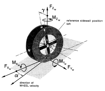
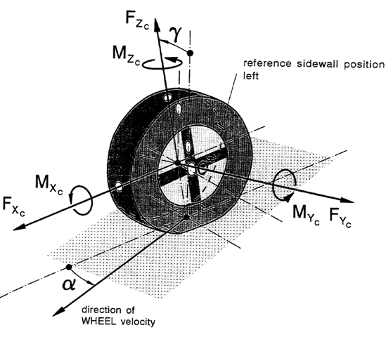
The force and moment data should represent the steady state tire force and moments in the contact point in between the tire and the road. Both the PAC2002 and PAC-MC require data in the so called TYDEX [1] W axis system (ISO) (See also Axis Systems and Slip Definitions in PAC2002 Tire Model or Axis Systems and Slip Definitions in PAC-MC Tire Model.).
An example of a PAC2002 conventional Force and Moment test program is given in following table:
Slip condition | Vertical load [N] | Slip angle [deg] | Inclination angle [deg] | Long. Slip [-] |
|---|---|---|---|---|
Pure lateral slip | Fz1, Fz2, Fz3 | -12 - +12 | -5, 0, 5 deg | Free rolling |
Pure longitudinal Slip | Fz1, Fz2, Fz3 | 0 | 0 | -100% - 0 - 100% |
Combined slip | Fz1, Fz2, Fz3 | -1, 1, 3, 5, 8 | -5, 0, 5 deg | -100% - 0 - 100% |
For the PAC-MC model, the camber range for the pure cornering conditions and (if possible) the combined slip conditions should be extended:
Slip condition | Vertical load [N] | Slip angle [deg] | Inclination angle [deg] | Long. Slip [-] |
|---|---|---|---|---|
Pure lateral slip | Fz1, Fz2, Fz3 | -10 - +10 | -5, 0, 5, 10, 15, 25, 35, 45 deg | Free rolling |
Pure longitudinal Slip | Fz1, Fz2, Fz3 | 0 | 0 | -100% - 0 - 100% |
Combined slip | Fz1, Fz2, Fz3 | -1, 1, 3, 5, 8 | -5, 0, 5, 10, (15), 25, (35), 45 deg | -100% - 0 - 100% |
In addition to the conditions in terms of vertical load, camber, longitudinal and lateral slip specified in this example test program, inflation pressure changes may be added (pure slip conditions) so that also inflation pressure effects can be derived during the parameter calculation.
Another more sophisticated method focused on testing the tire under realistic conditions is the so-called TIME tire testing procedure, see Reference 2.
Note that in all cases the test conditions should cover the conditions that a tire may 'experience' during the simulation analyses.
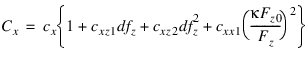
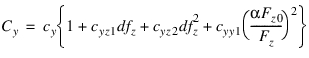
2. Basic tire property data
Loaded radius data
When analyzing the vertical load calculation of the PAC2002 or PAC-MC model (see also Equation (8) in section Contact Methods and Normal Load Calculation), changes in speed, lateral force, longitudinal force and camber have an effect on the tire stiffness.
For common vehicle handling simulations with a passenger car, the deflection - load relation is often sufficient. This will require a test that measures vertical load as function of the tire deflection (distance of the axle to the road) for determining the coefficients qFz1 and qFz2. When higher accuracy is required, the effects of the tire forces (Fx and/or Fy), camber and speed could be added (qFcx1, qFcy1,  ). In addition tests can be added to identify the effect of inflation pressure (qpFz1).
). In addition tests can be added to identify the effect of inflation pressure (qpFz1).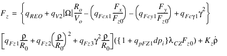 | (1) |
Parameter qRE0 corrects for possible differences in between the specified unloaded radius (R0) and the measured radius.
Note: | When the height of the wheel axle to the road is measured during the force and moment tests, the F&M data can also be used for the loaded radius calculations. |
Effective rolling radius
The effective rolling radius is a 'virtual' radius defined as
 | (2) |
See also equation 11 in Contact Methods and Normal Load Calculation
In order to derive the effective rolling radius coefficients (Breff, DReff, FReff, and qRE0 for possible inconsistency in the unloaded radius) the test data should provide the kinematic rolling radius ( ) as a function of load.
) as a function of load. Rolling Resistance Moment
The rolling resistance moment is defined as
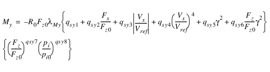 | (3) |
See also formula (110) of the PAC2002 tire model manual.
Contact Patch geometry
The contact patch length and width should be measured for 3 different vertical loads in order to derive the coefficients for the contact length. Half the contact length (a) is defined with
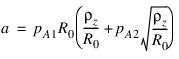 | (4) |
While half the contact width is defined by
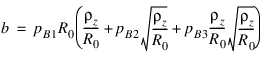 | (5) |
See also the section 3D Enveloping Contact.
Longitudinal and lateral relaxation length
The lateral relaxation length is defined with:
 | (6) |
While the equation for the longitudinal relaxation reads:
 | (7) |
See also the section Transient Behavior in PAC2002, the linear transient model. For PAC-MC the formulae for the relaxation length read:

See also the section Transient Behavior in PAC MC.
Similar to the contact patch geometry, for determining the relaxation length parameters the relaxation should be measured at 3 vertical load values.
An alternative for providing the relaxation length data, is providing the longitudinal and lateral stiffness of the non-rolling tire as a function of load. Then the TDFT will estimate the relaxation with following estimations:
 | (8) |
and
 | (9) |
 | is the cornering stiffness (Ky) |
 | is the lateral stiffness of the tire |
 | is the longitudinal slip stiffness (Kx) |
 | is the longitudinal stiffness of the tire |
Advanced longitudinal and lateral relaxation length (Optional)
If more accuracy is required for transient response, but no belt dynamics data is available, one can consider to use the advanced (non-linear) transient of PAC2002 or PAC-MC. In that case the USE_MODE should be set in the range of 21 until 25, see section 'Non linear transient model'.
In the linear transient model the relaxation depends on the (non-rolling) longitudinal and lateral stiffness of the tire. In advanced (non-linear) transient these stiffness parameters can be dependent on load and slip according to following formulae:
 | (10) |
 | (11) |
See also the section Transient Behavior in PAC2002 and Transient Behavior in PAC MC, the non-linear transient model.
For calculating the advanced longitudinal and lateral relaxation, the TDFT requires relaxation length values as function of load and slip. The relaxation should be measured with a slip step input to the tire at low rolling speed (max. 5 m/s).
3. Advanced Dynamics (not applicable for PAC-MC)
With the advanced dynamics the parameters for the advanced transient model (use mode > 24) can be determined. The longitudinal and lateral stiffness of the non-rolling tire should be provided for the for at least three loads to determine these stiffness values:
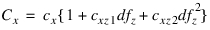 | (12) |
 | (13) |
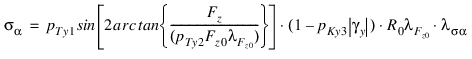
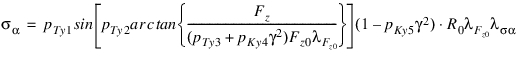
The torque when turning the non-rolling tire around the z-axis yields the yaw stiffness and peak torque as function of load:
 | (14) |
See also the section Transient Behavior in PAC2002.
4. Enveloping and Belt Dynamics (not applicable for PAC-MC)
Enveloping
For determining the parameters of the 3D Enveloping contact, the dimension of the cams and the contact length factor (see also the section 3D Enveloping Contact) has to be calculated.
For this the TDFT needs tire 'cleat test data' at low speed (< 2 m/s), to avoid tire inertia effects.
The tire should roll over a cleat perpendicular to the wheel plane (cleat length and height approx. 5% of the tire radius) at fixed axle height. The enveloping optimization process requires vertical load data as function of time or travelled distance for at least 3 heights (loads), measured in the wheel spindle (force of the wheel on the axis) in the so-called TYDEX C-axis system.
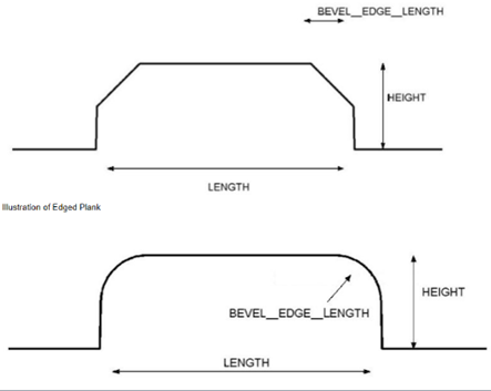
The geometry of the cleat should be described as done for the Adams 2D Road and Adams 3D Spline road using cleat height, cleat length and the bevel edge.
In addition to the cleat geometry, the TDFT will need information about the inertia of the rim about the wheel axis.
Vertical and Longitudinal Belt dynamics
Cleat tests similar to the tests for the Enveloping need to be provided for the Vertical and Longitudinal Belt dynamics, however the tests should be performed at moderate speeds, so that the cleat will excite the belt dynamics.
The cleat geometry can be similar to the cleat geometry used in the Enveloping tests. In addition to the vertical force also the longitudinal force by the tire on the axis should be measured. Again test data at 3 vertical axle positions (3 loads) should be provided. The test can be done at one speed, but for capturing the effect of speed on the dynamics, multiple speeds are preferred.
Inertia of the rim and, if applicable, additional inertia of the testrig, around the wheel axle should be provided in the TYDEX data files as well.
Lateral Belt dynamics
For exiting the belt dynamics in lateral the direction, the cleat should be changed to an oblique position. The angle of the cleat with the wheel plane should be around 45 deg.
Again cleat testing at 3 loads at a moderate speed (preferably more than one speed) is required. In addition to the vertical load, also the lateral force of the tire on the wheel axle must be measured.
Tire Data File Format
The general supported format for the tire test data is TYDEX [1]. For the Force and Moment testing also a TeimOrbit format is supported, though TYDEX is preferred because the Import Tire Properties button (Tire Fit View) works with TYDEX only.
Example TYDEX data files are available in Adams Tire release folder:
- $topdir/atire/tiredata/car, for a car tire.
- $topdir/atire/tiredata/motorcycle, for a motorcycle tire.
These TYDEX files form the blue-print for the data format that is accepted by the TDFT.
In order to achieve a high level of consistency and reproducibility, it is advised to add all relevant information about the tire, the test and the test rig in the TYDEX data file.
Import Tire Properties
When clicking on the Import Tire Properties button in the Tire Fit View, following information found in the **CONSTANT block will be imported into the tire database:
NOMWIDTH Nominal section width of tire mm 205
ASPRATIO Nominal aspect ratio % 55
RIMDIAME Nominal rim diameter inch 16
RIMWIDTH Rim width inch 6.5
INFLPRES Inflation pressure bar 2.5
TYREMASS Tyre mass kg 9.3
MANUFACT Manufacturer - -
IDENTITY Identity - 205/55 R16 90H
TRCKSURF Surface of track - asphalt
TRCKCOND Condition of track surface - dry
TRAJVELW Trajectory velocity m/s 16.67
Note: | Import Tire Properties will import this additional tire info only when this info is consistent over all files being selected in Tire Fit View. |
For each type of fit the required data and the TYDEX format will be described
1. Force and Moment tire data format
FX_PURE
The format for a TYDEX file suitable for the FX_PURE fit type should have following elements in the **CONSTANT and **MEASURCHANNEL block:
The format for a TYDEX file suitable for the FX_PURE fit type should have following elements in the **CONSTANT and **MEASURCHANNEL block:
**CONSTANTS
! preferably import tire properties info added here
SLIPANGL slip angle rad 0.0
INCLANGL nominal inclination angle rad 0.0
FZW nominal wheel load N 2300
**MEASURCHANNELS
SLIPANGL slip angle rad
LONGSLIP longitudinal slip -
INCLANGL inclination angle rad
FZW vertical load N
FX longitudinal N
FYW lateral force N
MXW overturning moment Nm
MZW aligning torque Nm
INFLPRES inflation pressure Pa 1.0 0.0 0.0
FY_PURE, MX_PURE and MZ_PURE
The format for a TYDEX file suitable for the FY_PURE, MX_PURE and MZ_PURE fit types should have following elements in the **CONSTANT and **MEASURCHANNEL block:
The format for a TYDEX file suitable for the FY_PURE, MX_PURE and MZ_PURE fit types should have following elements in the **CONSTANT and **MEASURCHANNEL block:
**CONSTANTS
! preferably import tire properties info added here
LONGSLIP longitudinal slip - 0.0
INCLANGL nominal inclination angle rad 0.087266
FZW nominal wheel load N 2300
**MEASURCHANNELS
SLIPANGL slip angle rad 1.0 0.0 0.0
LONGSLIP longitudinal slip - 1.0 0.0 0.0
INCLANGL inclination angle rad 1.0 0.0 0.0
FZW vertical load N 1.0 0.0 0.0
FX longitudinal N 1.0 0.0 0.0
FYW lateral force N 1.0 0.0 0.0
MXW overturning moment Nm 1.0 0.0 0.0
MZW aligning torque Nm 1.0 0.0 0.0
INFLPRES inflation pressure Pa 1.0 0.0 0.0
FX_COMBINED, FY_COMBINED, MX_COMBINED and MZ_COMBINED
The format for a TYDEX file suitable for the FX_COMBINED, FY_COMBINED, MX_COMBINED and MZ_COMBINED fit types should have following elements in the **CONSTANT and **MEASURCHANNEL block:
The format for a TYDEX file suitable for the FX_COMBINED, FY_COMBINED, MX_COMBINED and MZ_COMBINED fit types should have following elements in the **CONSTANT and **MEASURCHANNEL block:
**CONSTANTS
! preferably import tire properties info added here
SLIPANGL slip angle rad -0.174533
INCLANGL nominal inclination angle rad 0.0
FZW nominal wheel load N 2300
**MEASURCHANNELS
SLIPANGL slip angle rad
LONGSLIP longitudinal slip -
INCLANGL inclination angle rad
FZW vertical load N
FX longitudinal N
FYW lateral force N
MXW overturning moment Nm
MZW aligning torque Nm
INFLPRES inflation pressure Pa 1.0 0.0 0.0
Note: | The signals as defined in the **CONSTANT block determine whether a file is considered as a pure cornering, pure longitudinal slip or combined slip test. |
2. Basic property data format
LOADED_RADIUS
The format for a TYDEX file suitable for the LOADED_RADIUS fit type should have following elements in the **CONSTANT and **MEASURCHANNEL block:
The format for a TYDEX file suitable for the LOADED_RADIUS fit type should have following elements in the **CONSTANT and **MEASURCHANNEL block:
**CONSTANTS
! preferably import tire properties info added here
LONGVEL Longitudinal velocity m/s 14.04
**MEASURCHANNELS
FZW Vertical Force N 1 0 0
DSTGRWHC Dist. ground - wheel centre m 1 0 0
INCLANGL nominal inclination angle rad 1 0 0
FX longitudinal N 1 0 0
FYW lateral force N 1 0 0
The green channels are optional.
EFFECT_RADIUS
The format for a TYDEX file suitable for the EFFECT_RADIUS fit type should have following elements in the **CONSTANT and **MEASURCHANNEL block:
The format for a TYDEX file suitable for the EFFECT_RADIUS fit type should have following elements in the **CONSTANT and **MEASURCHANNEL block:
**CONSTANTS
! preferably import tire properties info added here
LONGVEL Longitudinal velocity m/s 14.04
**MEASURCHANNELS
FZW Vertical Force N 1 0 0
KROLRAD Kinematic rolling radius m 1 0 0
ROLLING_RESIST
The format for a TYDEX file suitable for the ROLLING_RESIST fit type should have following elements in the **CONSTANT and **MEASURCHANNEL block:
The format for a TYDEX file suitable for the ROLLING_RESIST fit type should have following elements in the **CONSTANT and **MEASURCHANNEL block:
**CONSTANTS
! preferably import tire properties info added here
LONGVEL Longitudinal velocity m/s 14.04
**MEASURCHANNELS
FZW Vertical Force N 1 0 0
MYW rolling resistance moment Nm 1 0 0
See also the alternative method for providing the rolling resistance data.
CONTACT_PATCH
The format for a TYDEX file suitable for the CONTACT_PATCH fit type should have following elements in the **CONSTANT and **MEASURCHANNEL block:
The format for a TYDEX file suitable for the CONTACT_PATCH fit type should have following elements in the **CONSTANT and **MEASURCHANNEL block:
**CONSTANTS
! preferably import tire properties info added here
**MEASURCHANNELS
FZW Vertical force N 1 0 0
CONTACTL Contact length (2a) m 1 0 0
CONTACTW Contact width (2b) m 1 0 0
RELAX_X and RELAX_Y
The format for a TYDEX file suitable for the RELAX_X and RELAX_Y fit types should have following elements in the **CONSTANT and **MEASURCHANNEL block:
The format for a TYDEX file suitable for the RELAX_X and RELAX_Y fit types should have following elements in the **CONSTANT and **MEASURCHANNEL block:
**CONSTANTS
! preferably import tire properties info added here
**MEASURCHANNELS
FZW Vertical force N 1 0 0
RLXLENX Long. relaxation length m 1 0 0
RLXLENY Lateral relaxation length m 1 0 0
An alternative for the supplying data to derive the relaxation length is the lateral and longitudinal tire stiffness of the non-rolling tire as a function of load. In that case the file format for the RELAX_X and RELAX_Y fit types should have following elements in the **CONSTANT and **MEASURCHANNEL block:
**CONSTANTS
! preferably import tire properties info added here
**MEASURCHANNELS
FZW Vertical force N 1 0 0
CXTYRE Longitudinal stiffness N/m 1 0 0
CYTYRE Lateral stiffness N/m 1 0 0
When supplying the lateral tire stiffness, the relaxation length is estimated by:

In which  is the lateral relaxation length,
  the cornering stiffness and CFy the lateral stiffness of the tire. A similar approach is used for the longitudinal relaxation length.
is the lateral relaxation length, the cornering stiffness and CFy the lateral stiffness of the tire. A similar approach is used for the longitudinal relaxation length.LONG_CM_STIFFNESS
For fitting the advanced transient parameters in longitudinal direction (LONG_CM_STIFFNESS) with relaxation, the following data file layout should be used:
For fitting the advanced transient parameters in longitudinal direction (LONG_CM_STIFFNESS) with relaxation, the following data file layout should be used:
**CONSTANTS
! preferably import tire properties info added here
**MEASURCHANNELS
FZW Vertical force N 1 0 0
LONGSLIP Longitudinal slip - 1 0 0
RLXLENX Long. relaxation length m 1 0 0
**MEASURDATA
3000 0.01 0.198045
...
LAT_CM_STIFFNESS
Similar for fitting the advanced transient parameters in lateral direction (LAT_CM_STIFFNESS) with relaxation, the following data file layout should be used:
Similar for fitting the advanced transient parameters in lateral direction (LAT_CM_STIFFNESS) with relaxation, the following data file layout should be used:
**CONSTANTS
! preferably import tire properties info added here
**MEASURDATA
FZW Vertical force N 1 0 0
SLIPANGL Slip Angle deg 1 0 0
RLXLENY Lateral relaxation length m 1 0 0
**MEASURDATA
3000 0.1 0.315021
...
Note: | The method chosen for the calculation of the lateral relaxation length used for the tire testing should agree with the method selected in the TDFT, for more information see here. |
3. Advanced Dynamics file format (not applicable for PAC-MC)
The calculation of Advanced Dynamics parameters requires two types of data: longitudinal and lateral stiffness data of the non-rolling tire and parking torque data.
STIFFNESS_X
The format for a TYDEX file suitable for the STIFFNESS_X fit type should have following elements in the **CONSTANT and **MEASURCHANNEL block
The format for a TYDEX file suitable for the STIFFNESS_X fit type should have following elements in the **CONSTANT and **MEASURCHANNEL block
**CONSTANTS
TRAJVELW Trajectory velocity m/s 0.0
INCLANGL nominal inclination angle deg 0.0
**MEASURCHANNELS
FZW Vertical Force N 1 0 0
CXTYRE Longitudinal stiffness N/m 1 0 0
STIFFNESS_Y
The format for a TYDEX file suitable for the STIFFNESS_Y fit type should have following elements in the **CONSTANT and **MEASURCHANNEL block:
The format for a TYDEX file suitable for the STIFFNESS_Y fit type should have following elements in the **CONSTANT and **MEASURCHANNEL block:
**CONSTANTS
TRAJVELW Trajectory velocity m/s 0.0
INCLANGL nominal inclination angle deg 0.0
**MEASURCHANNELS
FZW Vertical Force N 1 0 0
CYTYRE Longitudinal stiffness N/m 1 0 0
PARKING
The format for a TYDEX file suitable for the PARKING fit type should have following elements in the **CONSTANT and **MEASURCHANNEL block:
The format for a TYDEX file suitable for the PARKING fit type should have following elements in the **CONSTANT and **MEASURCHANNEL block:
**CONSTANTS
TYREMASS Tyre mass kg 9.3
RIMROTIN Rim rotational inertia kgm2 1.11
TRGROTIN Test rig rot. inertia kgm2 0.9
TYROTIN Tyre rot. inertia about YC kgm2 1.5
TYRESTIN Tyre steer inertia about ZC kgm2 0.83
TRAJVELW Trajectory velocity m/s 0.0
INCLANGL nominal inclination angle deg 0.0
FZW nominal wheel load N 3000
**MEASURCHANNELS
RUNTIME Running time s 1 0 0
STEEANGL Steer angle rad 1 0 0
INCLANGL Inclination angle N 1 0 0
FZW Vertical force N 1 0 0
MZW Aligning torque Nmm 1 0 0
The TYDEX file should contain the data of a non-rolling tire, rotated about the vertical z-axis with a sine wave reaching the maximum parking torque.
4. Enveloping and Belt Dynamics file format (not applicable for PAC-MC)
The TYDEX files for the calculating the parameters for enveloping and belt dynamics properties contain the measured forces in the wheel hub (forces on the spindle) when rolling over a cleat a fixed axle height.
Next to the measured forces, also information about the cleat geometry and the testrig wheel inertia should be available in the data files. Note that the optimizer assumes a fixed time increment in between two data points during the complete test.
ENVELOPING
The format for a TYDEX file suitable for the ENVELOPING fit type should have following elements in the **CONSTANT and **MEASURCHANNEL block:
The format for a TYDEX file suitable for the ENVELOPING fit type should have following elements in the **CONSTANT and **MEASURCHANNEL block:
**CONSTANTS
! preferably import tire properties info added here
RIMROTIN Rim rotational inertia kgm2 1.11
TRGROTIN Test rig rot. inertia kgm2 0.9
TYROTIN Tyre rot. inertia about YC kgm2 1.5
TYRESTIN Tyre steer inertia about ZC kgm2 0.83
CLEAT_H Cleat height m 0.015
CLEAT_L Cleat length m 0.015
CLEAT_RA Cleat rotation angle rad 1.5708
CLEATBEV Cleat Bevel Edge m 0.0
FZC Vertical force N 2000
LONGVEL Longitudinal velocity m/s 0.0762
**MEASURCHANNELS
RUNTIME Running time s 1 0 0
FX Longitudinal force N 1 0 0
FYC Lateral force N 1 0 0
FZC Vertical force N 1 0 0
Note: | For ENVELOPING the TDFT expects test data measured at a forward speed (LONGVEL) smaller than 2 m/s. |
VERTICAL_BELT and LONG_BELT
The format for a TYDEX file suitable for the VERTICAL_BELT and LONG_BELT fit types should have following elements in the **CONSTANT and **MEASURCHANNEL block:
The format for a TYDEX file suitable for the VERTICAL_BELT and LONG_BELT fit types should have following elements in the **CONSTANT and **MEASURCHANNEL block:
**CONSTANTS
! preferably import tire properties info added here
RIMROTIN Rim rotational inertia kgm2 1.11
TRGROTIN Test rig rot. inertia kgm2 0.9
TYROTIN Tyre rot. inertia about YC kgm2 1.5
TYRESTIN Tyre steer inertia about ZC kgm2 0.83
CLEAT_H Cleat height m 0.015
CLEAT_L Cleat length m 0.015
CLEAT_RA Cleat rotation angle rad 1.5708
CLEATBEV Cleat Bevel Edge m 0.0
FZC Vertical force N 2000
LONGVEL Longitudinal velocity m/s 11.1111
**MEASURCHANNELS
RUNTIME Running time s 1 0 0
FX Longitudinal force N 1 0 0
FZC Vertical force N 1 0 0
Note: | The Cleat rotations angle should be 90 deg. |
LATERAL_BELT
The format for a TYDEX file suitable for the LATERAL_BELT fit type should have following elements in the **CONSTANT and **MEASURCHANNEL block:
The format for a TYDEX file suitable for the LATERAL_BELT fit type should have following elements in the **CONSTANT and **MEASURCHANNEL block:
**CONSTANTS
NOMWIDTH nominal section width of tire mm 205
ASPRATIO nominal aspect ratio % 55
RIMDIAME nominal rim diameter inch 16
RIMWIDTH rim width inch 6.5
INFLPRES inflation pressure bar 2.5
TYREMASS Tyre mass kg 9.3
TRCKCOND Condition of track surface - dry
RIMROTIN Rim rotational inertia kgm2 1.11
TRGROTIN Test rig rot. inertia kgm2 0.9
TYROTIN Tyre rot. inertia about YC kgm2 1.5
TYRESTIN Tyre steer inertia about ZC kgm2 0.83
CLEAT_H Cleat height m 0.015
CLEAT_L Cleat length m 0.015
CLEAT_RA Cleat rotation angle rad 0.7854
CLEATBEV Cleat Bevel Edge m 0.0
FZC Vertical force N 2000
LONGVEL Longitudinal velocity m/s 11.1111
**MEASURCHANNELS
RUNTIME Running time s 1 0 0
FXC Longitudinal force N 1 0 0
FYC Lateral force N 1 0 0
FZC Vertical force N 1 0 0
References
1. H.-J. Unrau, J. Zamow, TYDEX-Format, Description and Reference Manual, Release 1.1, Initiated by the International Tire Working Group, July 1995.
2. J.J.M.van Oosten e.a., TIME, Tire Measurements, Forces and Moments, a new standard for steady state cornering tyre testing, EAEC Congress, STA99C209, 1999, Barcelona.